Top 10 Creative ATtiny85 Project Ideas of 2026
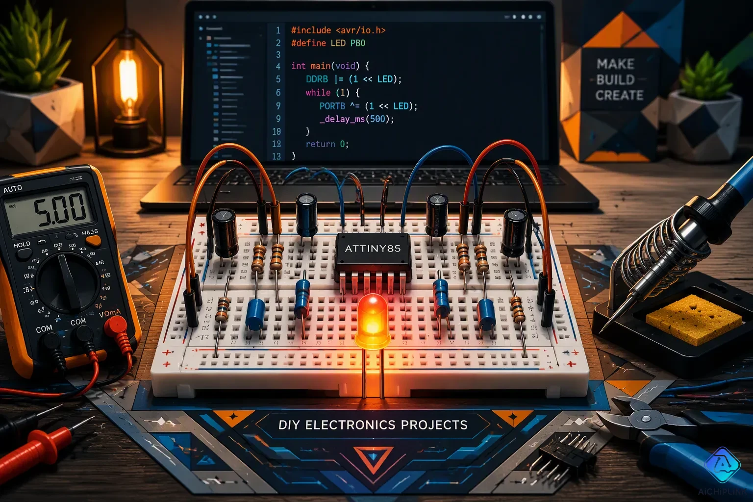
Eight pins. That is all the room you need for a keyboard, a game console, or a tiny satellite. The ATtiny85 puts real power into a cheap, small chip, and it uses the same language as Arduino. That blend makes it a top microcontroller for makers who want to save money.
Creative ATtiny85 project ideas come in all shapes. You can build a USB keystroke injector, a small game console, a wireless mailbox notifier, a soil moisture meter, or a countdown timer. Other projects include a cube satellite, an EMF detector, a sleep aid, LED dice, and a POV display. Each project lists parts, difficulty, and key technical points.
Key Takeaways
-
The ATtiny85 is a small, cheap chip that can power many creative projects.
-
You can build projects for any skill level, from simple timers to advanced satellites.
-
Most projects need only basic tools and parts that cost under $20.
-
Each project teaches you useful skills like coding, wiring, and problem-solving.
-
Start with a beginner project and share your build to inspire others.
Creative ATtiny85 Project Ideas at a Glance
How Projects Were Chosen
I picked these ten projects with three filters in mind. First, each one had to show real creativity. A blinking LED is fine for practice, but it does not earn a spot on this list. Second, every build had to be feasible for a hobbyist with basic tools. You should not need a reflow oven or a lab bench to finish any of them. Third, I favored beginner-friendly builds whenever possible, so newcomers can jump in without feeling lost.
The range here stretches from wearables to games to wireless gadgets. Some projects take an evening. Others might eat a weekend or two. That spread matters because your time and skill level shape what you pick. You will find simple timers sitting next to advanced satellite demos. Each entry gives you the parts list, the difficulty rating, and the key technical points. That way you can compare projects side by side and choose the one that fits your bench.
Skill Levels Covered
The ten projects split into three rough tiers. Beginners can start with the soil moisture meter, the countdown timer, the sleep aid, or the LED dice. These builds use few parts and simple logic. You will practice reading sensors, driving LEDs, and writing basic sketches. Intermediate makers get the USB injector, the game console, the mailbox notifier, the EMF detector, and the POV display. These add libraries, timing tricks, or wireless links.
Advanced builders should look at the cube satellite. It packs multiple sensors and a telemetry link into one tiny board. That project tests your skills in power management and data handling. No matter your level, the ATtiny85 keeps the barrier low. The chip costs very little, and the Arduino IDE supports it. You can fail fast, learn quickly, and try again. That loop turns small creative challenges into real confidence.
1. USB Keystroke Injector
How It Works
You plug a small board into a computer, and it starts typing on its own. That is the magic of a USB keystroke injector. The attiny85 sits at the heart of this trick. It runs the V-USB library, which is a software USB stack. This library lets the chip act like a standard USB HID keyboard. Your computer sees a normal keyboard, not a strange device.
The V-USB library handles enumeration through the HID Boot Protocol. It sends explicit USB descriptor strings for the manufacturer and product. The device uses the shared V-USB VID/PID of 16c0:27db. Operating systems recognize it as a generic keyboard right away. V-USB manages all the low-level USB communication. The firmware then handles HID reports and keyboard layouts. You get full keystroke injection without any extra hardware. This makes it one of the most talked-about attiny85 projects for security testing.
Components and Difficulty
The parts list stays short and cheap. You need an attiny85 chip, a USB connector, a few resistors, and the right firmware. A breadboard and jumper wires help during testing. The table below breaks down what each part does.
| Component | Purpose |
|---|---|
| attiny85 | Runs the V-USB firmware |
| USB connector | Links the chip to your computer |
| Resistors | Stabilize the USB data lines |
| Firmware | Sends the keystroke commands |
This build lands at the intermediate level. You should know basic Arduino programming before you start. You also need to flash the V-USB firmware onto the chip. That step takes some care. Many other attiny85 projects skip USB entirely, so this one teaches you a new skill. Once it works, you can program it to type passwords, open terminals, or run scripts. Just use it responsibly on your own machines.
2. Tiny Game Console
You can build a pocket-sized video game console with an attiny85. It drives a small OLED screen and reads button presses. The whole thing fits in your palm. This is one of those creative attiny85 projects that feels like magic the first time you see it work.
Game Library and Display
The display is an SSD1306 OLED. It measures 128 by 64 pixels. That tiny screen can show simple graphics, text, and basic animations. You control the action with a few tactile buttons. The graphics library handles all the drawing commands. You just tell it where to put pixels.
What games can you run on this tiny console? A dice game works as the simplest option. It uses one pushbutton, a resistor, a breadboard, and a few wires. You press the button to roll. The screen shows the result. That game is a starting point for bigger projects. You can also play a Breakout clone. That classic brick-breaking game runs smoothly on the attiny85. Another title is UFO Escape. It is an obstacle-avoiding side-scroller. You dodge objects as you fly across the screen. You can program these games yourself and load them onto the chip.
All these games live directly on the chip. There are no cartridges. To change games, you swap out a programmed DIP processor. That keeps the hardware simple and the cost low. You can program multiple chips and swap them anytime.
The chip handles all the game logic and display updates. You need to manage timing carefully. It runs at 8 MHz, so you cannot waste cycles. But for simple arcade-style games, it works great. Many of these projects push the microcontroller to its limits in a fun way.
Components and Difficulty
The parts list stays short. You need an attiny85, an SSD1306 OLED display, tactile buttons, and a battery. A breadboard helps during testing. You might add a voltage regulator for stable power. A small switch turns the console on and off. A resistor pulls up the I2C lines for the display.
| Component | Purpose |
|---|---|
| Microcontroller | Runs the game code and drives the display |
| SSD1306 OLED | Shows game graphics and score |
| Tactile buttons | Player input for movement and actions |
| Battery | Portable power source |
This build sits at the intermediate level. You need to know basic Arduino programming. You also need to wire an I2C display and handle button debouncing in software. The OLED library and the game logic take some work to combine. But the result is a real console you can carry in your pocket. It makes a great weekend project. You can find many similar projects online that build on this core idea.
3. Wireless Mailbox Notifier
How the RF Link Works
You place a small circuit inside your mailbox. A reed switch sits near the door. When the door opens, a magnet moves away from that switch. The switch closes and tells the attiny85 that mail has arrived.
The chip then sends a signal through a 433MHz RF transmitter. This transmitter pushes a short burst of data across the air. The receiver unit sits somewhere inside your home. It picks up that signal and triggers a buzzer. You get a clear alert that mail has landed. The whole process takes less than a second.
The RF link uses simple on-off keying. You do not need complex encryption or pairing. The receiver decodes the signal and passes it to another attiny85 on the receiving end. That chip drives the buzzer. Most 433MHz modules reach about 100 meters in open air. That range covers a typical suburban yard without trouble.
Power management keeps this build running for months. The mailbox circuit runs on batteries. You want it to sleep almost all the time. The attiny85 can enter a deep sleep mode that draws almost no current. It wakes up only when the reed switch triggers. That trick lets the batteries last for months instead of weeks.
Components and Difficulty
The parts list stays short. You need two attiny85 chips, one for each end of the link. Two 433MHz RF modules handle the wireless part. A reed switch detects the mailbox door opening. A buzzer gives you the alert inside the house. A few resistors, a capacitor for stability, and small battery packs finish the build.
| Component | Purpose |
|---|
| attiny85 (x2) | Controls the transmitter and receiver circuits |
|---|---|
| 433MHz RF modules | Send and receive the wireless signal |
| Reed switch | Detects when the mailbox opens |
| Buzzer | Alerts you when mail arrives |
| Battery packs | Powers both the mailbox and indoor units |
This build sits at the beginner to intermediate level. If you have wired up a simple LED circuit before, you can handle this one. The tricky part is tuning the RF modules to talk to each other reliably. You may need to experiment with antenna length and placement. But once you get a solid link, the system works without fuss for months.
Among practical attiny85 projects, this notifier stands out. It saves you from walking to the mailbox just to find it empty. Many creative attiny85 projects use this same RF pair for wireless communication. That makes this build a perfect introduction to wireless basics. You learn battery management, RF protocols, and interrupt handling all in one small box.
4. Soil Moisture Meter
Sensing and Feedback
You can save your houseplants with a tiny circuit that watches the soil. A soil probe measures how much water sits around the roots. The attiny85 reads that signal and decides if the soil is too dry. When moisture drops, the chip lights an led to warn you. This is one of the most practical attiny85 projects for plant lovers.
The YL-38 decoder board handles the sensing. It sends a digital signal to pin 0 of the chip. You set that pin as an input with a pull-up resistor. The chip then mirrors that reading to two output pins. One pin drives a red led for dry soil. The other pin drives a green led for wet soil. The code below shows this logic in action.
void setup() { pinMode(0, INPUT_PULLUP); pinMode(1, OUTPUT); pinMode(2, OUTPUT); }
void loop() { digitalWrite(1, digitalRead(0)); digitalWrite(2, !digitalRead(0)); }
Components and Difficulty
The parts list is short and cheap. You need an attiny85, a YL-38 soil probe, an RGB led, and a resistor. A small battery pack powers everything. Here is how you wire it up.
-
YL-38 Decoder: Vcc to battery +, Ground to pin 3 of ATtiny, Digital output to pin 0.
-
RGB LED (common anode): Vcc to battery + via resistor, Red cathode to pin 1, Green cathode to pin 2.
-
ATtiny85: Vcc to battery +, Ground to battery -.
This build sits at the beginner level. You only need basic soldering skills and a simple sketch. The attiny85 handles the logic without any complex libraries. Among beginner attiny85 projects, this one teaches you digital input, output control, and sensor basics. You can finish it in an afternoon. Once it works, you can expand it with more leds or a buzzer. Many creative projects start with this simple plant-saving circuit.
5. Countdown Timer
A countdown timer is one of those projects you can build in an evening. Set a time, press a button, and wait. When the countdown hits zero, a buzzer sounds and an led lights up. This simple circuit uses an attiny85 to handle all the timing logic. It is a perfect starting point for beginners who want to try more complex projects later.
Timing Logic
The timing logic is straightforward. Your code tracks seconds using the chip's internal clock. You set a starting value. The chip counts down from that number. Every second it checks if the time reaches zero. At zero, the microcontroller triggers the buzzer and the led.
You control the timer with push buttons. One button sets the countdown value. Another button starts the countdown. A third button resets everything. The attiny85 reads each button press. You debounce the buttons in software. That stops false readings from electrical noise. The code uses delay functions or the millis() timer for accuracy. You adjust the timing intervals easily by changing one variable.
The buzzer and the led give you clear feedback. The buzzer beeps once at the end. The led stays lit until you reset the circuit. You can add multiple indicator lights to show the remaining time. Each light represents a segment of the countdown. The chip has enough pins for that upgrade. Many beginner builds use this same pattern.
Components and Difficulty
The parts list is short. You need an attiny85, a buzzer, a few indicator lights, and push buttons. A breadboard and jumper wires help during testing. A battery pack powers everything. You can also use a USB cable.
Connect the buzzer to one output pin. Connect each light to its own output pin with a resistor. Connect each button to an input pin. Use the chip's internal pull-up resistors. The wiring takes about ten minutes. Test on a breadboard before soldering.
This build sits at the beginner level. You need basic soldering skills and a simple Arduino sketch. The attiny85 handles all the logic. You finish the circuit in an afternoon. The timer works reliably for hours.
Creative projects like this teach you timing control, button input, and output signaling. These skills transfer to other builds. You can expand this timer with a display later. The core concepts stay the same. This is one of the most practical projects for learning how microcontrollers handle time.
6. Tiny Cube Satellite
Sensor Payload
You make a small satellite demo that fits in your hand. It holds an attiny85, an accelerometer, a temperature sensor, and an RF module on one small board. The unit checks its surroundings and sends data back to you.
The accelerometer (like an ADXL335) measures which way it is tilted. It shows you how the satellite is pointing. The temperature sensor reads the air temperature nearby. This chip reads both sensors every few seconds. It packs that data into a short message. The RF module sends that message to a ground station you set up close by.
This copies how real satellites work. Real ones use solar panels and complex radios. Yours uses simple hobby parts. But the main idea is the same. Sensors gather data. A microcontroller processes it. A transmitter sends it home. You learn real telemetry skills without launching anything.
This chip does all the thinking. It reads sensors through analog and digital pins. Then it formats the data and fires the RF module. The whole loop runs on a tight power budget. You tune the code to save energy.
Many makers use these creative projects to teach STEM ideas. This tiny satellite demo makes space feel within reach. Friends and students find it really cool.
Components and Difficulty
You need a few key parts for this build. The attiny85 acts as the brain. An accelerometer senses movement and tilt. A temperature sensor (like the DS18B20) measures heat. A 433MHz RF module sends the data. A small battery powers everything. You can add a solar cell for a realistic demo.
| Component | Purpose |
|---|---|
| attiny85 | Controls sensor readings and RF transmission |
| Accelerometer | Measures orientation and tilt |
| Temperature sensor | Reads ambient temperature |
| 433MHz RF module | Transmits telemetry data |
| Battery pack | Provides portable power |
This build ranks as advanced among attiny85 projects. You need experience with sensors and wireless links. You must understand I2C or SPI communication. Power management adds another challenge. You cannot waste battery life for long demos.
The payoff is worth the effort. You get a working satellite telemetry system on your desk. Experiment with data logging and range testing. This is one of the most rewarding projects for learning space-style electronics. Many advanced projects build on these same sensor and radio skills.
7. EMF Detector
Detecting Fields
You can build a ghost-hunting style detector that senses electromagnetic fields around wiring, appliances, or anything else that gives them off. The attiny85 reads a signal from a wire coil antenna. That coil picks up changes in the magnetic field close by. An op-amp makes the weak signal stronger so the chip can process it. When the field strength goes past a set level, the attiny85 lights an led and drives a speaker. The led blinks faster as you move closer to the source. The speaker clicks or buzzes at the same speed. That feedback helps you trace wires inside walls or find hidden electronics.
This build teaches you analog sensing and signal conditioning. You learn how to boost tiny voltages and turn them into data you can read. The attiny85 handles the logic without any trouble. Many creative projects use this same sensor-and-feedback loop. You can adjust the sensitivity with a potentiometer or by changing a resistor value in your code.
Components and Difficulty
The parts list includes an attiny85, a wire coil antenna, an op-amp, an led, and a speaker. You also need resistors, capacitors, and a battery pack. A breadboard helps during testing. The table below shows what each part does.
| Component | Purpose |
|---|---|
| attiny85 | Reads the amplified signal and controls output |
| Wire coil antenna | Picks up electromagnetic fields |
| Op-amp | Amplifies the weak coil signal |
| led | Shows field strength visually |
| Speaker | Gives audio feedback |
This build sits at the intermediate level. You need basic soldering skills and some experience with analog circuits. The op-amp stage requires careful wiring to avoid noise. Once it works, you have a handheld detector that responds to live wires, motors, and power supplies. Among attiny85 projects, this one mixes science and fun. You can carry it around and test everyday objects. The led and speaker make the invisible visible. That instant feedback keeps you interested. Many similar projects add a sensitivity knob or a second led for direction. You can grow this circuit as your skills get better.
8. DodowDIY Sleep Aid
Breathing Light Pattern
You can build a small device that helps you fall asleep by syncing your breath to a soft light. The idea is simple. A gentle glow expands and contracts at a slow, steady pace. You watch the light and match your breathing to it. This calms your nervous system and quiets your mind. The attiny85 handles the timing perfectly.
The light pattern starts faster and then slows down. This gradual shift trains your body to relax. Here is the pacing the original Dodow device uses.
According to the source, the Dodow device starts with 11 breaths per minute and gradually reduces to 6 breaths per minute over an 8-minute duration.
You can program your attiny85 to follow that same curve. The chip fades an led up and down using PWM. A diffuser sits over the led to soften the glow. That soft light fills the room without harsh edges. You can run this pattern for 8 minutes and then shut off automatically. Many sleep-focused projects use this exact approach. The attiny85 sleeps between cycles to save battery.
Components and Difficulty
The parts list is short and affordable. You need an attiny85, an RGB led, a diffuser, and a battery. A resistor limits current to the led. A small switch turns the device on and off. The table below shows what each part does.
| Component | Purpose |
|---|---|
| attiny85 | Controls the breathing light timing |
| RGB led | Produces the soft glowing light |
| Diffuser | Spreads the light for a gentle effect |
| Battery | Powers the portable device |
This build sits at the beginner level. You only need basic soldering skills and a simple sketch. The attiny85 handles PWM output without any complex libraries. Among beginner-friendly projects, this one delivers real value. You can finish it in an afternoon. The led and diffuser combo creates a professional look. You can also add a second led for a different color. That small change makes the device feel personal. Creative projects like this show how one chip can improve your daily routine.
9. LED Dice
Randomness and Display
You build a dice that never wears out. No faded dots. No chips on the corners. Just a shake and a roll that shows your number on seven tiny lights. The attiny85 handles everything inside.
Here is how it works. You give the board a shake. A tilt sensor detects the motion. The attiny85 then runs a quick random number routine. It reads a value from an unconnected analog pin. That pin picks up ambient electrical noise. The chip uses that noise as a seed for the random generator. The result is a number between one and six.
The chip then lights up the right pattern on seven LEDs. Each number has a standard pip arrangement. One lights the center led. Two lights the top-left and bottom-right. Three adds the center. Four lights all four corners. Five adds the center to the corners. Six lights two columns of three. The attiny85 maps each number to the correct pins. You see the result instantly.
The tilt sensor keeps the dice honest. You cannot trigger a roll by tapping a button. You have to shake the whole device. That action feels like rolling a real dice. The random routine is good enough for board games. No one can predict the next number.
Components and Difficulty
The parts list is short and affordable. You need one attiny85 chip. You need a tilt sensor or a mercury switch. Seven lights and seven current-limiting resistors make the display. A battery pack powers everything. A breadboard helps you test the circuit first.
| Component | Purpose |
|---|---|
| attiny85 | Generates the random number and controls the lights |
| Tilt sensor | Detects when you shake the device |
| Seven lights | Display the dice pips in the standard pattern |
| Resistors (x7) | Limit current to each led |
| Battery pack | Provides portable power |
Connect each led to a separate pin on the attiny85. Wire the tilt sensor between ground and another pin with a pull-up resistor. The setup takes about twenty minutes on a breadboard. You can transfer it to protoboard later.
This build sits at the beginner level. You need basic soldering skills and a simple Arduino sketch. The attiny85 uses a short program. You generate the random number. Then you write a function for each dice face. Each function turns on the right combination of led units. The tilt sensor calls the random function when it closes.
Among beginner attiny85 projects, this one feels like real magic. Your friends see a custom electronic dice in your pocket. You can change the number of lights or add an auto-off timer. Many creative projects build on this idea. You see similar projects online all the time. Other small projects can reuse the random number code. The core skills you learn here transfer to any future build.
10. POV Display
Persistence of Vision Explained
You have seen those spinning gadgets that spell words in thin air. That trick is a persistence-of-vision display. Your eye holds onto an image for a split second after the light disappears. Spin a row of lights fast enough, and your brain blends each flash into a solid picture. The attiny85 makes this possible on a small budget.
Here is how the build works. You mount a small board on a spinning arm. A motor turns that arm at high speed. A magnet and a reed switch tell the chip where each rotation begins. The attiny85 then fires the led strip at precise moments. Each led becomes one pixel in a moving column. Time those flashes right, and letters appear to float in the air. The chip has just enough speed and memory for short words or simple shapes.
Components and Difficulty
The parts list is short but the wiring demands care. You need an attiny85, a small led strip, a motor, a magnet, a reed switch, and a battery pack. A driver transistor helps the chip switch the strip without burning out. The table below shows what each part does.
| Component | Purpose |
|---|---|
| attiny85 | Times each led flash during rotation |
| led strip | Draws the pixels in mid-air |
| Motor | Spins the arm at speed |
| Magnet and reed switch | Marks the start of each rotation |
| Battery pack | Powers the spinning board |
This build sits at the intermediate to advanced level. You must balance the spinning arm or it wobbles. You also need tight timing code, since the attiny85 has few cycles to spare. Among attiny85 projects, this one rewards patience. Many creative projects look impressive, but few match the wow factor of text floating in space. Start slow, tune the timing, and your led display will amaze your friends.
Getting Started with ATtiny85
Essential Equipment
You do not need a fancy lab to start building attiny85 projects. The parts are cheap and easy to find. Here is what every beginner needs.
-
attiny85 microcontroller – a blank new chip works fine. You program it through another board.
-
Arduino Uno – set this up as an ISP programmer. It loads your code onto the attiny85.
-
FTDI USB-to-Serial interface – costs about $2 to $12. Some chips need an extra driver on your PC.
-
Solderless breadboard and DuPont jumper wires – these let you test circuits without soldering.
-
100 nF ceramic capacitor – stabilizes the reset line.
-
10k ohm resistor – also for the reset line.
-
330 ohm resistor – drives LEDs safely.
You can get all these parts for under $20. The Arduino Uno programs the attiny85. The FTDI adapter lets you debug later. The capacitor and resistors keep your attiny85 projects running smoothly. These basic attiny85 projects will teach you the core skills you need.
A solid tip: buy two or three attiny85 chips at once. They cost very little. Having extras lets you test without worry.
Programming Basics
The Arduino IDE is free software. Install it first. Then add the ATtiny core through the Board Manager. That step teaches the IDE how to talk to your attiny85.
The upload process is the same as for any Arduino board. Write a sketch. Pick your board from the menu. Hit upload. Select "ATtiny25/45/85" from the Board menu. Then choose the correct chip and clock speed. For most builds, the 8 MHz internal clock works well. Check the Burn Bootloader step if your chip is blank. That prepares the attiny85 to accept sketches.
The blink sketch works as a perfect first test. Wire an LED to pin 0 with the 330 ohm resistor. Watch it flash. That blink tells you the whole chain works.
Many creative attiny85 projects follow this same workflow. Code. Upload. Test. Debug. You reuse the same hardware for every new build. The attiny85 runs at 8 MHz. You can build dozens of attiny85 projects with this simple setup. The chip costs so little that you can keep several programmed and ready to swap. Start with a simple blink sketch. Then move on to the countdown timer or the LED dice. Each project teaches the same basic skills in a new way. You build confidence with every successful upload.
More ATtiny85 Projects and Resources
Learning Resources
You can learn a lot from a few good books. "Make: AVR Programming" by Elliot Williams teaches you how to work with AVR chips directly. That knowledge helps you push your attiny85 projects further. "Arduino Cookbook" by Michael Margolis gives you recipes for common tasks. You can adapt those recipes to your own builds. Online, the Arduino Playground wiki holds a treasure chest of attiny85 projects. You will find code samples, wiring diagrams, and troubleshooting tips there.
YouTube channels like GreatScott and Andreas Spiess cover creative attiny85 project ideas in plain language. They show you the build process step by step. You can follow along and pause when you need to. Many of their projects use the same parts you already own. That makes learning cheap and fast.
Community and Repositories
The Arduino Forum is the first place to ask questions. Thousands of makers share their attiny85 projects there. You can search old threads before you post. Someone has likely solved your problem already. Hackaday and Hackaday.io host a huge collection of projects. You can browse finished builds and read the code behind them. GitHub also holds many repositories for attiny85 projects. Search for "attiny85" and you will find libraries, example sketches, and full project files.
Reddit communities like r/arduino and r/AskElectronics welcome beginners. You can post photos of your build and get feedback. Instructables and Hackster.io offer step-by-step guides for hundreds of projects. These sites let you share your own work too. When you finish a build, post it online. Your project might inspire someone else to start. That cycle keeps the maker community strong. Every project you share helps another builder learn.
You have seen ten creative attiny85 project ideas, from a simple soil moisture meter to an advanced cube satellite. Each build shows what this tiny chip can do. The attiny85 costs very little, welcomes beginners, and works again and again. You can reuse the same chip for new attiny85 projects whenever you like. Every build teaches you something new. So pick one project this week and start building. Grab your breadboard, flash a sketch, and watch it come alive. When you finish, share your build online. Your projects might spark an idea for another maker. That is how the community grows.

Written by Jack Elliott from AIChipLink.
AIChipLink, one of the fastest-growing global independent electronic components distributors in the world, offers millions of products from thousands of manufacturers, and many of our in-stock parts is available to ship same day.
We mainly source and distribute integrated circuit (IC) products of brands such as Broadcom, Microchip, Texas Instruments, Infineon, NXP, Analog Devices, Qualcomm, Intel, etc., which are widely used in communication & network, telecom, industrial control, new energy and automotive electronics.
Empowered by AI, Linked to the Future. Get started on AIChipLink and submit your RFQ online today!
Frequently Asked Questions
Do I need an Arduino to program an attiny85?
Yes, most beginners use an Arduino Uno as an ISP programmer. You wire the two boards together on a breadboard, then upload sketches through the Arduino IDE. A blank attiny85 needs the Burn Bootloader step first. After that, you program it like any other board.
How much does a starter setup cost?
You can gather the basics for under $20. That covers an attiny85 chip, an Arduino Uno, an FTDI adapter, a breadboard, jumper wires, a 100 nF capacitor, a 10k ohm resistor, and a 330 ohm resistor. Buy two or three chips at once so you can test without worry.
Which attiny85 projects suit a total beginner?
Start with the soil moisture meter, the countdown timer, the sleep aid, or the LED dice. Each one uses few parts and simple logic. You practice reading sensors, driving LEDs, and writing short sketches. These attiny85 projects build confidence fast, and you finish most of them in an afternoon.
Can the chip really run a game console or a satellite demo?
It can, with care. The attiny85 runs at 8 MHz, so you manage timing tightly. Simple arcade games and sensor telemetry both fit. The cube satellite adds an accelerometer, a temperature sensor, and a 433MHz RF module. That build ranks as advanced, so learn the basics first.
Where should I share my build when it works?
Post it on the Arduino Forum, Hackaday.io, Instructables, or Hackster.io. Reddit communities like r/arduino welcome beginners too. Photos and code help other makers learn. Your creative attiny85 project ideas might spark someone else's next build. That cycle keeps the community strong.