A delay circuit controls when an electrical device activates or deactivates by introducing a specific time gap between input and output. This type of circuit lets engineers set how long a device waits before starting or stopping. Many electronic devices, from smartphones to industrial machines, rely on delay circuits for precise timing. For example, a simple delay timer can help a light switch on after a short pause.
The demand for timing devices, including delay circuits, remains high in consumer electronics, automotive, and industrial sectors.
| Statistic / Data Point | Description |
|---|---|
| Consumer Electronics Market Share | Dominates timing devices market due to demand for precise timing in smartphones, tablets, wearables |
| Key Application Verticals | Consumer electronics, automotive, telecommunications, industrial, medical |
Key Takeaways
-
Delay circuits create a controlled pause between an input and output to manage when devices turn on or off, improving safety and performance.
-
Adjusting resistor and capacitor values in a delay circuit changes the delay time, following the simple formula: Delay time = 1.1 × R × C.
-
Common delay circuit types include analog (using resistors and capacitors), digital (using logic gates or microcontrollers), and programmable circuits for flexible timing control.
-
Time delay relays use delay circuits to automate and protect devices in industries and everyday appliances, ensuring machines start and stop at the right moments.
-
The 555 timer IC is a popular, easy-to-use component for building reliable delay circuits with adjustable timing for many applications.
Delay Circuit Basics
What Is a Delay Circuit
A delay circuit is a type of time-delay circuit that introduces a controlled pause between an input signal and the output response. Engineers use this circuit design to manage when a device turns on or off, ensuring precise timing in electronic systems. The basic construction often includes components such as a transistor, resistor, LED, and hookup wire.
-
The LED connects to the resistor.
-
The resistor links to the collector of the transistor.
-
The emitter of the transistor returns to the negative lead of the LED, completing the circuit.
Calibration plays a key role in achieving the desired delay. Adjusting the values of the resistor or other components allows fine-tuning of the delay timer circuit. The transistor acts as a switch, responding to voltage thresholds. When the voltage reaches a certain level, the transistor allows current to flow, activating the LED after a set time delay. Testing involves powering the circuit and measuring the time before the LED lights up, confirming both the delay and the accuracy of the calibration.
Note: Understanding each component’s function helps in adjusting the delay and improving circuit design for different timing needs.
How Delay Circuits Work
Delay circuits operate by controlling the timing of electrical signals. The most common time-delay circuit uses a combination of resistors and capacitors to store and release energy, creating a pause before the output activates. This timing circuit can be found in both analog and digital forms.
| Delay Circuit Type | Description | Key Characteristics |
|---|---|---|
| Chains of Inverter Gates | Digital delay created by chaining inverter gates, utilizing their propagation delay (0.5-10 ns per gate). | Simple, short delays (~tens of ns), approximate delay, impractical for very long delays. |
| Delay Line ICs | Dedicated ICs with internal inverter chains and taps for accurate digital delays. | Compensate for voltage/temperature variations, provide multiple taps, precise and stable delays. |
| Bucket Brigade Devices | Analog delay ICs using capacitor chains to 'shuffle' sampled voltages along the chain. | Used in audio processing, delays from ~5 ms to 200 ms, can be chained for longer delays. |
| Microcontroller-based | Uses ADC/DAC and FIFO memory buffers to delay analog or digital signals. | Highly configurable, suitable for complex signals, limited by sampling rate and memory size. |
A delay timer circuit can use digital or analog methods. For example, a digital delay circuit might chain inverter gates together, using the natural propagation delay of each gate to create a short, precise pause. This approach works well for very short delays, such as those needed in high-speed digital systems. In contrast, analog delay circuits often use capacitor chains, such as bucket brigade devices, to move sampled voltages along a path, producing longer delays useful in audio processing.
Some advanced time-delay circuits use microcontrollers. These circuits sample the input signal, store it in memory, and then output it after a set period. This method allows for highly configurable timing and can handle complex signals.
In practical applications, engineers often use a delay timer circuit to ensure that a device only activates after a specific event has settled. For instance, an analog delay circuit might use a diode bridge switched by a fast driver stage. This setup produces a clean, rapid pulse that triggers the delay, allowing the output to settle before the next action occurs. Oscilloscope traces show that such circuits can achieve precise timing, with outputs settling within a few nanoseconds.
A well-designed time-delay circuit ensures reliable operation in everything from simple light timers to complex industrial automation systems. The choice of circuit design depends on the required delay, the type of signal, and the level of precision needed.
Key Components of Time-Delay Circuits
RC Delay Element
The rc delay element forms the foundation of many time-delay circuits. This component uses a resistor and a capacitor to create a predictable pause in the circuit. When voltage applies to the rc delay element, the capacitor begins to charge through the resistor. The charging process follows a curve defined by the rc time constant. This constant determines how quickly the capacitor charges or discharges. Engineers use the rc delay element to set the delay time in simple circuits, such as light switches or alarms.
-
The rc delay element appears in Earth Leakage Circuit Breakers (ELCBs). These devices use a controlled delay to avoid tripping during harmless current surges.
-
Time delay fuses also rely on the rc delay element to handle short bursts of high current, such as when motors start up.
-
The rc delay element provides a cost-effective way to manage delay time in many everyday devices.
Tip: Adjusting the resistor or capacitor value changes the rc time constant, allowing precise control over the delay time.
555 Timer IC
The 555 timer IC stands out as one of the most popular integrated circuits for generating accurate delay time. This chip can operate in several modes, including monostable mode, which produces a single timed pulse. The 555 timer IC uses an internal rc delay element to set the timing interval. By selecting different resistor and capacitor values, engineers can adjust the rc time constant and, therefore, the delay time.
-
Time relays in industrial systems often use the 555 timer IC for reliable switching and timing control.
-
The 555 timer IC offers flexibility, making it suitable for both analog and digital delay circuits.
-
Many commercial and educational kits include the 555 timer IC because of its ease of use and precise timing.
A simple circuit with a 555 timer IC can control when a device turns on or off, ensuring safe operation in systems with high inrush currents.
Zener Controlled Switch
A zener controlled switch adds another layer of control to time-delay circuits. This component uses a zener diode to set a voltage threshold. When the voltage across the zener diode reaches a certain level, the switch activates, allowing current to flow. The zener controlled switch often works with an rc delay element to provide a stable and repeatable delay time.
-
Zener controlled switches appear in circuits that need to handle transient events, such as power surges or brief overloads.
-
These switches help prevent nuisance trips in systems like ELCBs and time delay fuses.
-
Engineers select zener diodes with specific voltage ratings to match the desired delay time and circuit requirements.
Note: Zener controlled switches improve the reliability of time-delay circuits, especially in environments with frequent voltage fluctuations.
Types of Delay Circuits
Analog Delay Circuit
Analog delay circuits use continuous electrical signals to create a time gap between input and output. These circuits often rely on resistor-capacitor (RC) networks or bucket brigade devices. An RC network forms the basis for many delay on timer and delay off timer applications. For example, a simple delay on timer circuit can control when a light turns on after a switch is pressed. Off-delay timers also use analog methods to keep a device running for a set period after the input signal stops.
Engineers often choose analog delay circuits for their simplicity and low cost. One shot timers and interval timers in analog form can be found in alarms, lighting controls, and basic automation systems. These circuits work well for tasks that do not require high precision or digital control.
Analog delay circuits provide reliable timing for everyday devices, such as off-delay timers in fans or recycle timers in irrigation systems.
Digital Delay Circuit
Digital delay circuits use logic gates, flip-flops, or microcontrollers to manage timing. These circuits offer higher precision and flexibility compared to analog designs. A digital delay on timer can control the exact moment a device activates, while a delay off timer ensures a device stays on for a precise interval after the trigger ends.
Researchers have compared different digital delay elements to find the best performance under changing conditions. The table below shows how three common digital delay elements perform:
| Design Specification | Best Performing Element | Middle | Worst Performing Element |
|---|---|---|---|
| Delay Resolution | Switched Capacitor Inverter (SCI) | Inverter Chain | Current-Starved Inverter (CSI) |
| Delay Range | Inverter Chain | CSI | SCI |
| Power Consumption | CSI | SCI | Inverter Chain |
| Area | CSI | Inverter Chain | SCI |
| Linearity | Inverter Chain | CSI | SCI |
| Robustness (Process Variation) | Inverter Chain | CSI | SCI |
| Robustness (Temperature) | SCI | CSI | Inverter Chain |
Digital delay circuits can adjust timing by changing control signals. For example, decreasing the controlling current in a digital delay element increases the delay time. This feature allows engineers to fine-tune delay on timer and delay off timer circuits for different applications. Off-delay timers and recycle timers in digital form appear in programmable logic controllers and modern automation systems.
Programmable Delay Circuit
Programmable delay circuits allow users to set or change the delay time using switches, software, or digital inputs. These circuits offer the most flexibility and can handle complex timing needs. A programmable delay on timer or delay off timer can be adjusted for different tasks without changing hardware.
Programmable delay circuits appear in many fields, from high-speed data transceivers to security hardware. The table below highlights some key applications and features:
| Application Domain / Feature | Description | Key Results / Highlights |
|---|---|---|
| High-speed data transceivers | Time-domain signal comparison, DFE operation | BER < 10^-12, energy efficiency 0.97 pJ/b at 32 Gb/s |
| Precision timing alignment | Digital delay line with stepped delays | Median deviation 1.9%, wide delay range |
| FPGA-based security | Ring oscillator PUF with programmable delay | High uniqueness, robust against attacks |
| MEMS gyroscope circuits | Programmable phase-demodulation delays | Low angle random walk, low current use |
One shot timers, interval timers, and recycle timers often use programmable delay circuits for advanced control. Off-delay timers in industrial automation can be programmed for different shutdown intervals, making these circuits ideal for changing requirements.
Tip: Programmable delay circuits give engineers the power to adapt timing functions quickly, improving system performance and flexibility.
Time Delay Relay and Timing Relays
Time Delay Relay Operation
A time delay relay controls the timing of electrical circuits by introducing a preset pause before switching contacts. This relay receives an input signal and then starts its timing process. The timing mechanism inside the relay can be electronic or electromechanical. During operation, the relay holds its initial contact state while the delay on timer or delay off timer counts down. After the set time delay, the relay changes its contact state, either closing or opening the circuit. The relay maintains this new state until the input signal is removed or reset.
The operation of a time delay relay follows a clear sequence:
-
The relay receives an input signal.
-
The timing mechanism activates and begins the countdown.
-
The relay holds its initial contact state during the timing period.
-
After the delay, the relay contacts switch state.
-
The relay keeps the new state until the input signal is removed or reset.
-
Some timing relays allow resetting the timing before the delay completes.
The table below shows how a time-delay circuit works in different real-world setups:
| Example Use Case | Description of Operation | Wiring Setup |
|---|---|---|
| Delayed Motor Start | The relay delays motor activation by a preset time, allowing controlled startup. | Power supply (+) → relay input; relay output → motor |
| Staircase Lighting Control | The relay keeps lights on for a set duration after a switch is pressed. | Power supply (+) → switch → relay input; relay output → light |
| Compressor Short Cycling Prevention | The relay introduces a delay between compressor starts to protect equipment. | Thermostat → relay input; relay output → compressor |
| Intermittent Wiper Operation | The relay controls the delay between wiper activations for intermittent wiping. | Wiper switch → relay input; relay output → wiper motor |
| Emergency Lighting Duration | The relay keeps emergency lights on for a preset time after power failure. | Power supply (+) → relay input; relay output → emergency light |
Tip: Using a time delay relay ensures that devices operate only after the correct timing, which protects equipment and improves safety.
Applications of Timing Relays
Timing relays play a vital role in many industries. They automate processes, improve safety, and provide precise timing control. On-delay timers prevent accidental starts and allow systems to stabilize before activation. Off-delay timers keep circuits energized for a set period after power is removed, which helps with controlled shutdowns. Delay on timer and delay off timer functions appear in lighting, HVAC, and safety systems.
-
Timer relays automate repetitive tasks such as conveyor belt movement, pump control, and mixing in process industries.
-
They enhance safety by ensuring machines turn off after a set time, reducing injury risks.
-
Applications include lighting control, irrigation, and emergency systems.
-
Benefits include increased efficiency, reduced human error, and freeing staff for other work.
-
Performance metrics such as electrical and mechanical life, power use, and temperature range support reliability.
One shot timers activate circuits for a set time after power is applied, which is common in machinery controls. Interval timers manage how long a load stays on, while recycle timers cycle loads on and off to save energy. Delay on timer and delay off timer features help tailor timing to each application. The NJS1 time-delay relay, for example, supports high voltage, has a long operational life, and works in harsh environments. Selecting the right timing relays involves checking contact ratings, time ranges, and environmental factors to ensure safe and reliable operation.
Delay Circuit Example
Step-by-Step Guide
A simple delay timer can be built using a 555 timer IC in monostable mode. This delay timer circuit creates a single output pulse after receiving a trigger. Many students and engineers use this approach for its reliability and ease of assembly.
Parts Needed:
-
555 timer IC
-
Resistor (R)
-
Capacitor (C)
-
Push-button switch
-
LED (for output indication)
-
Power supply (5V or 9V battery)
-
Breadboard and connecting wires
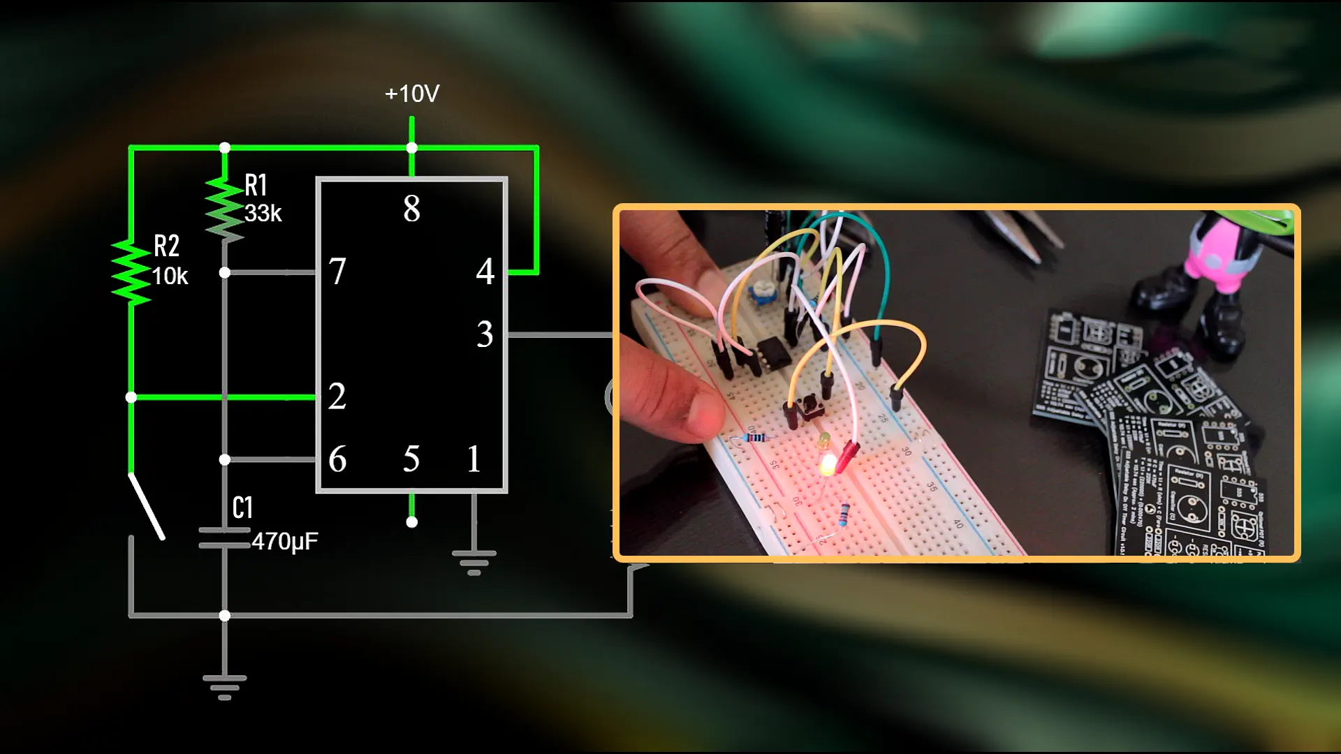
Wiring Steps:
-
Place the 555 timer IC on the breadboard.
-
Connect pin 1 to ground and pin 8 to the positive voltage.
-
Attach the resistor between pin 7 and pin 8.
-
Connect the capacitor between pin 6 and ground.
-
Link pin 6 and pin 2 together.
-
Attach the push-button switch between pin 2 and ground.
-
Connect the LED (with a current-limiting resistor) from pin 3 to ground.
-
Pin 4 connects to the positive voltage to enable the timer.
When the button is pressed, the delay timer circuit triggers. The output at pin 3 goes high, turning on the LED for a set delay time. After the delay, the LED turns off automatically.
The 555 timer IC uses three internal 5kΩ resistors to set reference voltages for its comparators. These comparators control the flip-flop and output stage, making the timing operation stable and repeatable.
Schematic Diagram:
   +V
    |
   [R]---+---[Pin 7]
         |         555 Timer IC
        [C]---[Pin 6,2]
         |         |
       GND       [Pin 1]
| Aspect | Description |
|---|---|
| Circuit Type | 555 Timer Monostable Circuit |
| Timing Formula | Delay time t = 1.1 × R × C |
| Example | 1-second delay with R = 91kΩ, C = 10µF |
| Working Principle | Triggering charges the capacitor, output pulse duration set by RC time |
| Output | LED lights up for the delay time, then turns off |
This simple delay timer works well for applications like delay on timer circuits in alarms or lighting systems. The delay on timer ensures that the device activates only after a set pause, which prevents false triggers or unwanted rapid switching.
Adjustable Delay Time
Adjusting the delay time in a delay timer circuit allows users to set different timing intervals for various needs. The delay time depends on the values of the resistor and capacitor in the RC network. The formula for the delay time is:
Delay time (t) = 1.1 × R × C
For example, to achieve a 500ms delay with a 10µF capacitor, calculate the resistor value as follows:
-
R = t / (1.1 × C) = 0.5 / (1.1 × 0.00001) ≈ 45.5kΩ
-
Choose the nearest standard resistor value, such as 47kΩ, which gives a delay time of about 517ms.
Tip: For longer delays, use a larger resistor instead of a very large capacitor. This approach keeps the circuit compact and improves accuracy.
| Test/Application Type | Calibration Tests or Procedures | Adjustable Design Parameters Relevant to Delay Accuracy |
|---|---|---|
| Delay Margin Test (CCD Sensor) | Adjust phase delay in fine increments until circuit failure to determine delay margin | Fine adjustability of delay between channels |
| Operational Amplifier Characterization | Use independently adjustable rise and fall times to account for asymmetrical response | Independently adjustable rise and fall times of waveform edges |
| Timing Margin Test (AFE for CCD Sensor) | Adjust trailing edge time independently while holding leading edge constant | Immediate effect of waveform parameter adjustments |
Switchable monostable circuits can provide variable delays by using a rotary switch or jumper wires to select different resistor values. This feature allows the delay on timer to match the timing needs of different devices. For precise timing, users can combine resistors in series or use capacitors with tighter tolerances.
A delay timer circuit can also include calibration tests. For example, engineers may activate synchronization modes and adjust the delay in small steps to verify the accuracy of the delay time. This process ensures that the delay on timer operates as expected in real-world conditions.
A well-designed delay timer circuit offers both reliability and flexibility. Adjustable delay time supports a wide range of applications, from simple delay timers in hobby projects to advanced delay on timer circuits in industrial automation.
Real-World Applications
Industrial Automation
Factories and production lines depend on precise timing to keep machines running smoothly. Engineers use a time delay relay to control the start and stop of motors, conveyor belts, and pumps. A time delay relay can prevent equipment from starting too soon after a power outage. This helps protect machines from damage. In many cases, a time delay relay ensures that one machine finishes its task before another begins.
A time delay relay also helps manage safety systems. For example, a time delay relay can keep emergency lights on for a set period after a power failure. Workers have enough time to exit safely. Timing relays play a key role in these systems. They provide reliable timing for alarms, warning lights, and shutdown procedures.
Note: Many industrial robots use a time delay relay to control the timing of each movement. This improves accuracy and reduces errors.
| Application Area | Use of Time Delay Relay | Benefit |
|---|---|---|
| Conveyor Systems | Delays motor start/stop | Prevents jams |
| Pump Control | Sets timing for pump cycles | Reduces wear |
| Safety Alarms | Controls alarm timing | Ensures proper warning |
| Lighting | Delays light activation | Saves energy |
Everyday Devices
People encounter a time delay relay in many household and office devices. For example, a time delay relay in a bathroom fan keeps the fan running after the light turns off. This removes moisture and prevents mold. Microwave ovens use a time delay relay to control the timing of cooking cycles.
A time delay relay also appears in washing machines. It manages the timing of water filling, washing, and spinning. Garage door openers use a time delay relay to keep the light on for a short time after the door closes. This gives users enough time to exit safely.
Timing relays help in security systems as well. They control the timing of sirens and lights when an alarm triggers. In many cases, a time delay relay makes devices safer and more convenient.
Tip: Replacing a faulty time delay relay in a device can restore proper timing and improve performance.
-
Common devices using a time delay relay:
-
HVAC systems
-
Automatic lighting
-
Security alarms
-
Kitchen appliances
-
A time delay relay helps control timing in many electronic systems. Engineers use timing to improve safety, efficiency, and performance. Time delay relay circuits allow machines to start and stop at the right moment. Careful adjustment of timing and component tolerances can boost reliability and yield, as shown in the table below. Anyone interested in electronics can build a simple time delay relay to learn how timing shapes modern devices.
| Metric / Aspect | Description / Impact |
|---|---|
| Settling Time | Minimum measurable settling time depends on resolution; below 160ns for 16-bit, increases to ~265ns at 20-bit due to switching residue. |
| Noise Limitations | Noise from DAC/amplifier and resistors limits resolution beyond ~15ppm without filtering or averaging. |
| Statistical Performance | Statistical models provide nominal values with ±3σ bounds, enabling prediction of circuit performance range. |
| Yield | Applying specification limits yields 97% for DC gain and 94% for frequency cut-off with current tolerances. |
| Component Tolerance Impact | Reducing tolerance of critical component (R2) from 10% to 1% improves yield to 99% (DC gain) and 96% (frequency cut-off). |
| Optimization Outcome | Further tolerance reduction to 1% achieves 100% yield, meeting specifications fully. |
FAQ
What is the main purpose of a delay circuit?
A delay circuit creates a controlled pause between an input and an output. Engineers use it to make sure devices turn on or off at the right time. This helps protect equipment and improve system performance.
How can someone adjust the delay time in a circuit?
Changing the resistor or capacitor values in the circuit will adjust the delay time. For example, increasing the resistor value makes the delay longer. Many circuits use a simple formula:
Delay time = 1.1 × R × C
Where do people use delay circuits in daily life?
People find delay circuits in devices like washing machines, microwave ovens, and automatic lights. These circuits help control when a device starts or stops, making everyday tasks safer and more convenient.
Can a delay circuit work with both analog and digital signals?
Yes, delay circuits can handle both analog and digital signals. Analog delay circuits use components like resistors and capacitors. Digital delay circuits use logic gates or microcontrollers for precise timing.
Why do engineers use a 555 timer IC in delay circuits?
The 555 timer IC offers reliable and adjustable timing. Engineers choose it because it works well in many applications, from simple alarms to industrial controls. The chip is easy to use and provides accurate delay times.
Written by Jack from AIChipLink.
AIChipLink, one of the fastest-growing global independent electronic components distributors in the world, offers millions of products from thousands of manufacturers, and many of our in-stock parts is available to ship same day.
We mainly source and distribute integrated circuit (IC) products of brands such as Broadcom, Microchip, Texas Instruments, Infineon, NXP, Analog Devices, Qualcomm, Intel, etc., which are widely used in communication & network, telecom, industrial control, new energy and automotive electronics.
Empowered by AI, Linked to the Future. Get started on AIChipLink.com and submit your RFQ online today!