Introduction to Electrical Circuits
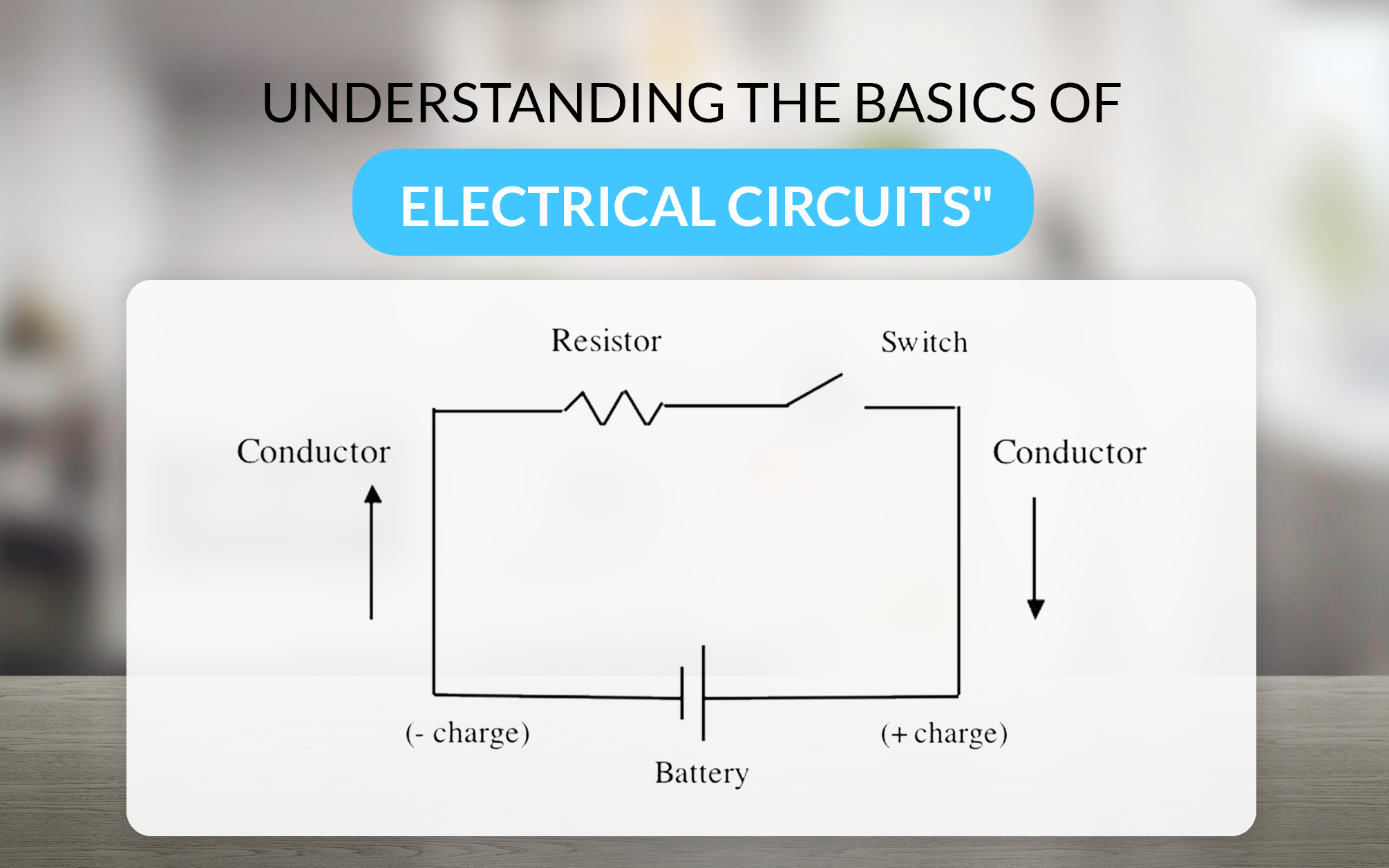
An electrical circuit is a closed loop through which electric current can flow. It consists of various components like resistors, capacitors, inductors, and power sources (such as batteries or generators) connected by conductive wires. The primary purpose of a circuit is to provide a path for electric current to travel, enabling the operation of electrical devices.
Basic Components of an Electrical Circuit
• Power Source: Provides the energy needed to drive the current through the circuit. Common examples include batteries and power supplies.
• Conductors: Wires or traces on a circuit board that allow current to flow.
• Load: The component that consumes electrical energy, such as a light bulb, motor, or resistor.
• Switches: Devices that can open or close the circuit, controlling the flow of current.
• Protective Devices: Fuses or circuit breakers that protect the circuit from overcurrent or short circuits.
Series and Parallel Circuits
Series Circuits
In a series circuit, all components are connected end-to-end, forming a single path for current to flow. The same current passes through each component, and the total voltage is the sum of the voltages across each component.
Characteristics of Series Circuits:
• Current: The same current flows through all components.
• Voltage: The total voltage is the sum of the individual voltages across each component.
• Resistance: The total resistance is the sum of the individual resistances.
Advantages:
• Simple to design and analyze.
• Suitable for applications where a single current path is sufficient.
Disadvantages:
• If one component fails, the entire circuit is interrupted.
• Not suitable for applications requiring different voltage levels.
Parallel Circuits
In a parallel circuit, components are connected across the same voltage source, providing multiple paths for current to flow. The voltage across each component is the same, and the total current is the sum of the currents through each component.
Characteristics of Parallel Circuits:
• Current: The total current is the sum of the currents through each component.
• Voltage: The same voltage is applied across all components.
• Resistance: The total resistance is less than the smallest individual resistance.
Advantages:
• If one component fails, the rest of the circuit continues to operate.
• Suitable for applications requiring different current levels.
Disadvantages:
• More complex to design and analyze compared to series circuits.
• Requires more wiring and components.
Comparison Table: Series vs. Parallel Circuits
| Aspect | Series Circuits | Parallel Circuits |
| Current | Same through all components | Sum of currents through each component |
| Voltage | Sum of voltages across each component | Same across all components |
| Resistance | Sum of individual resistances | Less than the smallest individual resistance |
| Failure Impact | Entire circuit fails if one component fails | Other components continue to operate |
| Complexity | Simple to design and analyze | More complex to design and analyze |
| Applications | Suitable for single current path | Suitable for different current levels |
Power Equation in Circuits
Power in an electrical circuit is the rate at which electrical energy is transferred by the circuit. The power equation is a fundamental concept in understanding how circuits operate and how energy is consumed or supplied.
Power Equation
The power P in a circuit can be calculated using the following equation:
P=VI
Where:
• P is the power in watts (W).
• V is the voltage in volts (V).
• I is the current in amperes (A).
This equation can be rearranged to solve for voltage or current:
V=PII=PV
Power in Series and Parallel Circuits
• Series Circuits: The total power is the sum of the power dissipated by each component. Since the current is the same through all components, the power dissipated by each component depends on its resistance.
Ptotal=P1+P2+P3+…
• Parallel Circuits: The total power is also the sum of the power dissipated by each component. However, since the voltage is the same across all components, the power dissipated by each component depends on its resistance and the current through it.
Ptotal=P1+P2+P3+…
Example Calculation
Consider a circuit with a 12V battery and two resistors in series: R1=4Ω and R2=6Ω.
1. Total Resistance: Rtotal=R1+R2=4Ω+6Ω=10Ω
2. Current: I=VRtotal=12V10Ω=1.2A
3. Power Dissipated by R1: P1=I2R1=(1.2A)2×4Ω=5.76W
4. Power Dissipated by R2: P2=I2R2=(1.2A)2×6Ω=8.64W
5. Total Power: Ptotal=P1+P2=5.76W+8.64W=14.4W
Superposition in Circuits
Superposition is a principle used in linear circuits to simplify the analysis of circuits with multiple power sources. The principle states that the total response in a linear circuit is the sum of the responses caused by each power source acting independently.
Steps to Apply Superposition
1. Turn off all independent power sources except one:
• Replace voltage sources with short circuits.
• Replace current sources with open circuits.
2. Analyze the circuit to find the response (current or voltage) due to the active power source.
3. Repeat the process for each power source.
4. Sum the individual responses to get the total response.
Example of Superposition
Consider a circuit with two voltage sources V1=10V and V2=5V, and two resistors R1=2Ω and R2=3Ω.
1. Analyze the circuit with V1 active and V2 turned off:
• Replace V2 with a short circuit.
• Calculate the current through R1 and R2
. Analyze the circuit with V2 active and V1 turned off:
• Replace V1 with a short circuit.
• Calculate the current through R1 and R2.
3. Sum the currents from both analyses to get the total current through each resistor.
Op-Amp Circuits
Operational amplifiers (op-amps) are versatile components used in a wide range of electronic circuits. They are commonly used in amplification, filtering, and signal conditioning applications.
Basic Op-Amp Circuit
An op-amp has two inputs (inverting and non-inverting) and one output. The output voltage is proportional to the difference between the two input voltages.
Inverting Amplifier:
• The input signal is applied to the inverting input.
• The output is 180 degrees out of phase with the input.
• The gain is determined by the ratio of the feedback resistor Rf to the input resistor Rin.
{out} = -\left(\frac{R_f}{R{in}}\right) V_{in} ]
Non-Inverting Amplifier:
• The input signal is applied to the non-inverting input.
• The output is in phase with the input.
• The gain is determined by the ratio of the feedback resistor Rf to the input resistor Rin.
{out} = \left(1 + \frac{R_f}{R{in}}\right) V_{in} ]
Applications of Op-Amp Circuits
• Signal Amplification: Increasing the amplitude of a signal.
• Filters: Removing unwanted frequencies from a signal.
• Comparators: Comparing two voltages and producing a digital output.
• Integrators and Differentiators: Performing mathematical operations on signals.
FAQs
Q1: What is the difference between series and parallel circuits?
A: In a series circuit, all components are connected end-to-end, forming a single path for current to flow. In a parallel circuit, components are connected across the same voltage source, providing multiple paths for current to flow.
Q2: How do you calculate power in a circuit?
A: Power in a circuit can be calculated using the equation P=VI, where P is power in watts, V is voltage in volts, and I is current in amperes.
Q3: What is superposition in circuits?
A: Superposition is a principle used in linear circuits to simplify the analysis of circuits with multiple power sources. The total response is the sum of the responses caused by each power source acting independently.
Q4: What are op-amp circuits used for?
A: Op-amp circuits are used for signal amplification, filtering, signal conditioning, and performing mathematical operations like integration and differentiation.
Q5: Can a circuit have both series and parallel components?
A: Yes, many circuits have both series and parallel components. These are called combination circuits and are analyzed by breaking them down into simpler series and parallel sections.
Conclusion
Electrical circuits are fundamental to the functioning of modern technology. Understanding the basics of series and parallel circuits, the power equation, and advanced concepts like superposition and op-amp circuits is essential for anyone working with electronics. Whether you're designing a simple circuit or analyzing a complex system, the principles discussed in this blog will serve as a solid foundation for your work.
By mastering these concepts, you'll be well-equipped to tackle a wide range of electrical engineering challenges, from designing efficient power systems to developing cutting-edge electronic devices. So, the next time you flip a switch or plug in a device, take a moment to appreciate the intricate world of circuits that makes it all possible.
Written by Icey Ye from AIChipLink.
AIChipLink, one of the fastest-growing global independent electronic component distributors in the world, offers millions of products from thousands of manufacturers. Whether you need assistance finding the right part or electronic components manufacturers for your design, you can contact us via phone, chat or e-mail. Our support team will answer your inquiries within 24 hours.
Disclaimer: This article is provided for general information and reference purposes only. The opinions, beliefs, and viewpoints expressed by the author of this article do not necessarily reflect the opinions, beliefs, and viewpoints of AIChipLink or official policies of AIChipLink.