Resistors in parallel share a unique configuration where their terminals connect to the same two points in a circuit. This arrangement ensures that all resistors experience the same voltage across them. Each resistor allows current to flow based on its resistance, creating a pathway for multiple currents to coexist. Engineers value this setup for its ability to reduce overall resistance and distribute current efficiently. Resistors in parallel play a vital role in designing circuits that require reliability, flexibility, or specific performance characteristics.
Key Takeaways
-
Resistors in parallel have the same voltage, making math easier.
-
Current splits between resistors. Less resistance means more current flows.
-
A formula helps find total resistance in parallel circuits quickly.
-
Parallel resistors make circuits reliable. If one breaks, others still work.
-
They are used in LED lights and power systems for better performance.
Current and Voltage in a Parallel Resistor Circuit
Voltage uniformity across parallel resistors
In a parallel resistor circuit, all resistors share the same voltage. This uniformity arises because each resistor connects directly to the same two points in the circuit. Regardless of the resistance value, the voltage across each branch remains constant. This principle simplifies calculations and ensures predictable behavior in the circuit.
Simulation data confirms this uniform voltage distribution. For example:
-
The voltage across each branch in a parallel circuit remains constant, enabling the application of the current divider rule.
-
This uniformity is essential for accurate calculations and proper circuit functionality.
The consistent voltage across resistors in parallel is a cornerstone of circuit design. It allows engineers to focus on current distribution without worrying about voltage variations across branches.
Current distribution based on resistance
In a parallel resistor circuit, current divides among the branches based on their resistance values. Each branch carries a portion of the total current, with lower-resistance branches conducting more current. This behavior follows the current divider rule, which states that current through a resistor is inversely proportional to its resistance.
Measured data highlights this relationship:
-
Branches with lower resistance carry a higher proportion of the total current.
-
The current divider formula demonstrates how resistance influences current distribution.
For instance, if one branch has half the resistance of another, it will carry twice the current. This predictable distribution makes parallel combinations ideal for applications requiring specific current flows.
The inverse relationship between resistance and current
The relationship between resistance and current in a parallel resistor circuit is inversely proportional. Georg Ohm's experiments in 1827 demonstrated this principle. By varying the voltage across a resistor and measuring the resulting current, Ohm confirmed that current increases as resistance decreases, provided the voltage remains constant. This linear relationship forms the basis of Ohm's law, expressed as ( V = I \times R ).
Comparative studies further illustrate this concept. For example:
| Study Title | Key Findings |
|---|---|
| A comparative numerical evaluation of linear anode arrangements for enhancing above ground storage tank cathodic protection | Higher resistance requires more voltage, resulting in lower current density distribution. |
This inverse relationship is crucial for understanding how resistors in parallel behave. It explains why circuits with multiple branches can distribute current efficiently, even when resistance values vary significantly.
How to Calculate Equivalent Resistance in Resistors in Parallel
The formula for equivalent resistance
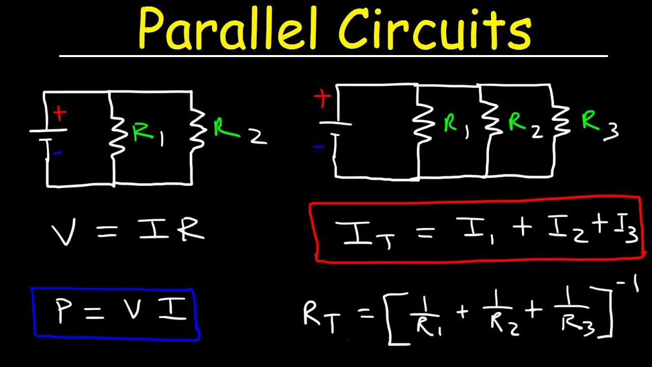
Calculating the equivalent resistance of resistors in parallel involves a specific formula. When resistors are connected in parallel, the reciprocal of the equivalent resistance equals the sum of the reciprocals of the individual resistances. This relationship is expressed as:
[ \frac{1}{R_{eq}} = \frac{1}{R_1} + \frac{1}{R_2} + \frac{1}{R_3} + \dots + \frac{1}{R_n} ]
Here, (R_{eq}) represents the equivalent resistance, while (R_1, R_2, R_3, \dots, R_n) denote the resistances of individual resistors in the parallel combination. This formula simplifies the analysis of circuits with multiple branches. For two resistors in parallel, the formula can be rewritten as:
[ R_{eq} = \frac{R_1 \cdot R_2}{R_1 + R_2} ]
This derivation is widely documented in textbooks and technical papers. The table below highlights some key concepts and their applications:
| Concept | Formula/Explanation |
|---|---|
| Equivalent Resistance | [R_{eq} = \frac{R_{1}R_{2}}{R_{1}+R_{2}}] (derived using the open/short-circuit approach) |
| Thévenin Equivalent | [v_{oc} = \frac{R_{2}}{R_{1}+R_{2}}v_{in}] (used to find open-circuit voltage) |
| Mayer-Norton Equivalent | [i_{eq} = \frac{v_{eq}}{R_{eq}}] (relationship for current source equivalent) |
| Application in Modeling | Describes how equivalent circuits can simplify analysis and model real-world components like batteries. |
Understanding this formula is essential for designing circuits with resistors in parallel. It allows engineers to predict how the circuit will behave under different conditions.
Step-by-step calculation example
To better understand the calculation process, consider the following example:
Problem:
Find the equivalent resistance of a circuit with three resistors in parallel: (R_1 = 6 , \Omega), (R_2 = 3 , \Omega), and (R_3 = 2 , \Omega).
Solution:
-
Apply the formula for equivalent resistance:
[ \frac{1}{R_{eq}} = \frac{1}{R_1} + \frac{1}{R_2} + \frac{1}{R_3} ] -
Substitute the given values:
[ \frac{1}{R_{eq}} = \frac{1}{6} + \frac{1}{3} + \frac{1}{2} ] -
Calculate the reciprocals and sum them:
[ \frac{1}{R_{eq}} = 0.1667 + 0.3333 + 0.5 = 1.0 ] -
Find the equivalent resistance:
[ R_{eq} = \frac{1}{1.0} = 1 , \Omega ]
This step-by-step process demonstrates how to calculate the equivalent resistance for resistors in parallel. The table below provides additional examples from academic sources:
| Step | Description | Calculation |
|---|---|---|
| (a) | Find total resistance of series and parallel combination | (R_{tot} = R_1 + R_p = 1.00 , \Omega + 4.11 , \Omega = 5.11 , \Omega) |
| (b) | Calculate IR drop in (R_1) | (V_1 = I \cdot R_1 = (2.35 , A)(1.00 , \Omega) = 2.35 , V) |
| (c) | Find current through (R_2) | (I_2 = V_p / R_2 = 9.65 , V / 6.00 , \Omega = 1.61 , A) |
These examples validate the formula and its application in real-world scenarios.
Special cases: Identical resistors and infinite resistance
Certain special cases simplify the calculation of equivalent resistance. When all resistors in a parallel combination have the same resistance, the formula becomes:
[ R_{eq} = \frac{R}{n} ]
Here, (R) is the resistance of each resistor, and (n) is the number of resistors in parallel. For example, if three identical resistors of (6 , \Omega) are connected in parallel, the equivalent resistance is:
[ R_{eq} = \frac{6}{3} = 2 , \Omega ]
Another special case occurs when one of the resistors has infinite resistance (an open circuit). In this situation, the resistor does not conduct current, and the equivalent resistance is determined by the remaining resistors. For instance, if two resistors in parallel are (R_1 = 4 , \Omega) and (R_2 = \infty), the equivalent resistance is:
[ R_{eq} = \frac{1}{\frac{1}{4} + \frac{1}{\infty}} = 4 , \Omega ]
These special cases highlight the versatility of the equivalent resistance formula. Engineers often use these principles to simplify circuit analysis and design.
Avoiding Common Mistakes in Parallel Resistor Circuits
Misunderstanding the equivalent resistance formula
One common mistake in analyzing a parallel resistive network is misapplying the equivalent resistance formula. This formula requires summing the reciprocals of individual resistances, then taking the reciprocal of the result. Errors often occur when individuals forget this final step or confuse the formula with that of resistors in series. Miscalculations can lead to incorrect predictions of circuit behavior, such as total current or power distribution.
Engineering guides emphasize the importance of understanding current division in parallel circuits. The total current splits among resistors based on their conductance. Misinterpreting this principle can result in errors when calculating equivalent resistance or current distribution. A clear grasp of the formula and its application is essential for accurate circuit analysis.
Ignoring the effects of extreme resistance values
Another frequent error involves overlooking the impact of extreme resistance values in a parallel combination. Resistors with very high or very low resistance can significantly influence the equivalent resistance and current flow. For instance, a resistor with infinite resistance (an open circuit) contributes no current, while a resistor with near-zero resistance can dominate the current flow.
The end customer must also evaluate whether a tolerance offered by a manufacturer is really practical. For example, some surface mount thin film chip resistors are offered in very tight tolerances for very low resistance values. That’s impressive on the datasheet but not compatible with assembly processes. As these resistors are mounted on the board there is a resistance change due to solder heat. The solder terminations melt, flow, and re-solidify with changed resistance values. For low-value resistors the amount of resistance change is much greater than the specified tolerance.
Understanding these effects helps engineers design circuits that remain stable under varying conditions.
Ensuring proper connections in parallel configurations
Improper connections in a parallel combination can lead to circuit instability or failure. For example, incorrect wiring may cause current imbalances or even short circuits. Engineers must ensure that all resistors connect to the same two points in the circuit to maintain proper functionality.
| Key Findings | Description |
|---|---|
| Stability of Parallel Configuration | The study demonstrates that cells connected in parallel can achieve stability, avoiding current runaway and system divergence. |
| Oscillation Concerns | Current on each branch may oscillate, but the configuration is shown to be robust and controllable. |
| Capacity Loss Warning | Despite stability, there are warnings about potential capacity loss and current overload in parallel configurations. |
Proper connections ensure that the parallel resistive network operates as intended, avoiding issues like oscillations or capacity loss.
Practical Applications of Resistors in Parallel
Achieving specific resistance values
Resistors in parallel provide a practical way to achieve precise resistance values that may not be available as single components. By combining resistors in a parallel combination, engineers can fine-tune the equivalent resistance to meet specific circuit requirements. This approach is especially useful when designing circuits for applications like sensor calibration or signal processing, where accuracy is critical.
For example, if a circuit requires a resistance of 2.5 Ω but only resistors of 5 Ω and 10 Ω are available, connecting these resistors in parallel achieves the desired value. Using the formula for equivalent resistance, the calculation shows:
[ R_{eq} = \frac{1}{\frac{1}{5} + \frac{1}{10}} = 2.5 , \Omega ]
This flexibility allows engineers to adapt to component availability while maintaining circuit performance.
Enhancing reliability and redundancy
Resistors in parallel improve circuit reliability by providing redundancy. If one resistor fails, the remaining resistors continue to conduct current, ensuring the circuit remains operational. This feature is particularly valuable in critical systems like medical devices or aerospace electronics, where uninterrupted functionality is essential.
Best practices for implementing redundancy include conducting sensitivity analyses and planning for maintenance. The table below outlines key strategies:
| Best Practice | Description |
|---|---|
| Utilize Redundancy Wisely | Implement parallel redundancy to improve reliability, but evaluate costs. |
| Conduct Sensitivity Analysis | Identify components with disproportionate impacts on system performance. |
| Plan for Maintenance | Schedule proactive repairs to prevent failures in critical configurations. |
These strategies help engineers balance reliability with cost-effectiveness, ensuring robust circuit designs.
Real-world examples: LED arrays and power systems
Resistors in parallel find widespread use in LED arrays and power systems. In LED arrays, parallel configurations ensure uniform brightness by distributing current evenly across each LED. This setup prevents individual LEDs from receiving excessive current, which could lead to overheating or failure.
Empirical research highlights the benefits of parallel resistors in these applications:
| Experiment Description | Key Findings |
|---|---|
| Current distribution in parallel resistors | Current splits evenly, optimizing performance in LED arrays. |
| LED brightness in parallel vs. series | LEDs in parallel maintain consistent brightness across the array. |
Power systems also benefit from parallel resistor configurations. By reducing overall resistance, these systems achieve higher efficiency and lower energy loss. This principle is applied in battery packs, where parallel resistors help balance current flow and extend battery life.
Resistors in parallel offer versatility and reliability, making them indispensable in modern circuit design.
Resistors in parallel exhibit predictable behavior that simplifies circuit analysis. Each resistor experiences the same voltage while carrying an individual current based on its resistance. Calculations for equivalent resistance follow a straightforward formula, ensuring accuracy and reproducibility.
-
Technical papers confirm these principles, highlighting unique current paths and consistent measurements across trials.
-
Ohm's law remains central to understanding how resistance influences current flow in parallel configurations.
Practical applications of resistors in parallel extend beyond theory. Fields like renewable energy and telecommunications rely on these circuits for efficiency and reliability. Electric vehicles use parallel battery setups to optimize energy storage, while smart homes integrate parallel circuits for uninterrupted power.
"In the realm of electrical engineering, understanding the behavior of parallel resistors is not optional, it's a necessity. Mastering this can redefine your approach to circuit design and, by extension, pave the way for breakthrough innovations," – Dr. Robert L. Boylestad.
By mastering the principles of resistors in parallel, engineers can design circuits that balance performance and reliability. Applying this knowledge in real-world scenarios fosters innovation and enhances technological advancements.
FAQ
1. Why does the voltage remain constant across resistors in parallel circuits?
The voltage stays constant because all resistors connect to the same two points in the circuit. This configuration ensures that each resistor experiences the same potential difference, regardless of its resistance value.
2. How does adding more resistors in parallel affect the equivalent resistance?
Adding more resistors in parallel decreases the equivalent resistance. Each additional resistor provides another pathway for current, reducing the overall resistance of the circuit.
3. Can resistors in parallel handle higher currents than a single resistor?
Yes, resistors in parallel distribute the total current among multiple branches. This arrangement allows the circuit to handle higher currents without overloading individual resistors.
4. What happens if one resistor in a parallel circuit fails?
If a resistor fails, the remaining resistors continue to conduct current. The circuit remains operational, though the equivalent resistance and current distribution may change.
5. Are parallel resistor circuits more efficient than series circuits?
Parallel circuits are often more efficient for applications requiring lower resistance and higher current flow. They also offer redundancy, ensuring reliability if one component fails.
Written by Jack from AIChipLink.
AIChipLink, one of the fastest-growing global independent electronic components distributors in the world, offers millions of products from thousands of manufacturers, and many of our in-stock parts is available to ship same day.
We mainly source and distribute integrated circuit (IC) products of brands such as Broadcom, Microchip, Texas Instruments, Infineon, NXP, Analog Devices, Qualcomm, Intel, etc., which are widely used in communication & network, telecom, industrial control, new energy and automotive electronics.
Empowered by AI, Linked to the Future. Get started on AIChipLink.com and submit your RFQ online today!