In the realm of electrical engineering and circuit analysis, understanding the behavior of currents in different circuit configurations is crucial. Among the various methods used to manage and distribute electrical currents, one of the key concepts is the current divider. While the term might sound complex at first, it refers to a relatively simple principle used in many circuits to split an incoming current into several branches. By understanding this principle, engineers and hobbyists can design circuits more efficiently and predict the flow of current accurately. In this blog, we’ll explore what a current divider is, how it works, and some practical applications of this concept in circuit design.
The Basics of Current Division
To begin with, it’s important to define what a current divider is. Simply put, a current divider is a method or tool used in electrical circuits to distribute a total current among multiple parallel branches. The current flowing through the main circuit is divided into portions that pass through the different parallel resistive elements, and the distribution depends on the resistance values of those elements.
The primary law governing the behavior of current in a parallel circuit is Ohm’s Law, which states that the current passing through a resistor is inversely proportional to the resistance value when the voltage across it remains constant. This is a fundamental concept when applying the current divider rule.
The Current Divider Rule (CDR)
The Current Divider Rule is a straightforward formula used to determine the amount of current that flows through each parallel branch in a circuit. The rule applies to circuits with two or more resistors connected in parallel. It allows you to calculate the current in each resistor without needing to solve for the entire circuit's behavior.
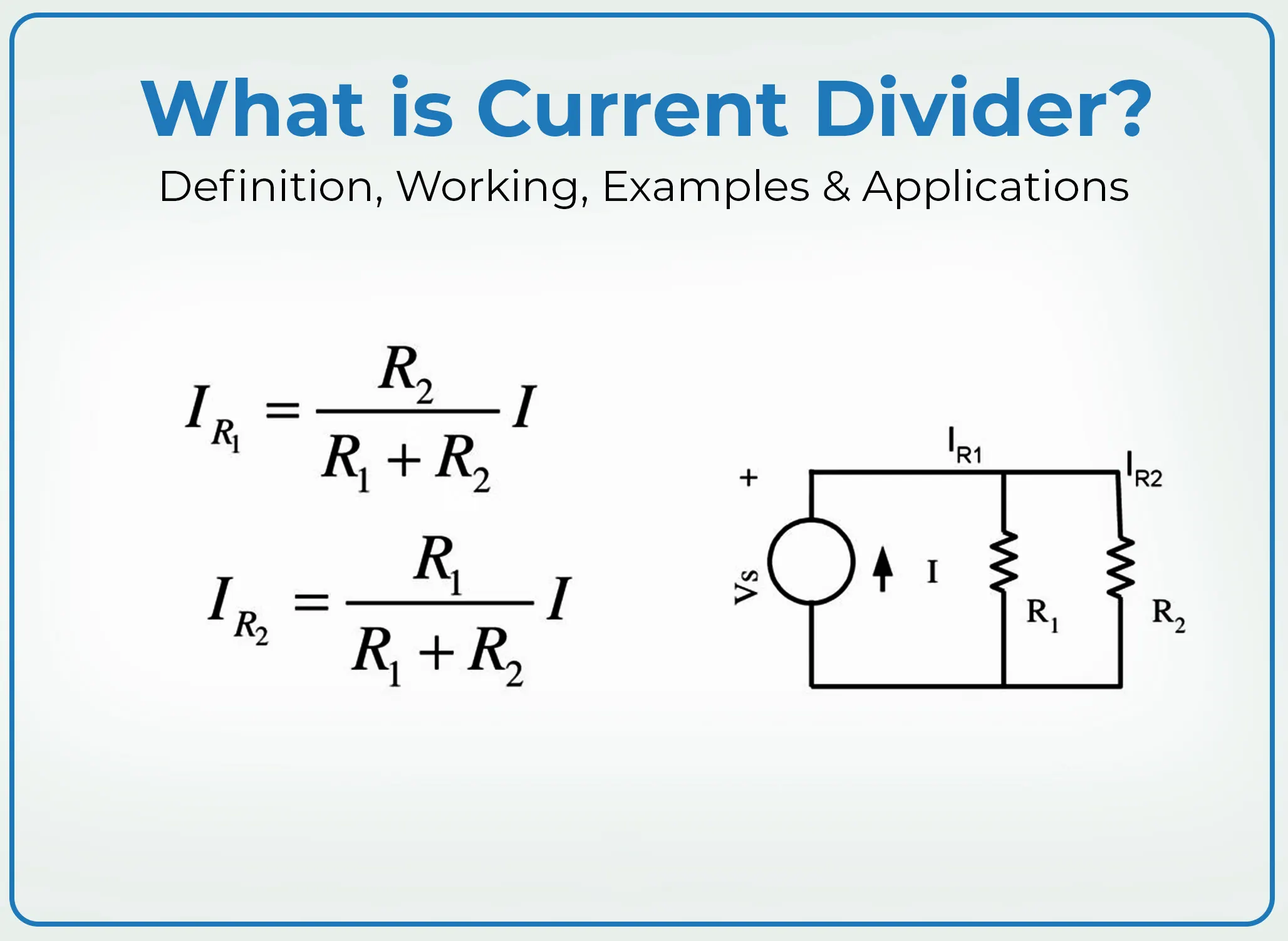
The formula for the current divider rule is:
Ix=Itotal×(RtotalRx)I_x = I_{total} \times \left( \frac{R_{total}}{R_x} \right)
Where:
• IxI_x is the current through the resistor RxR_x,
• ItotalI_{total} is the total current entering the parallel resistors,
• RtotalR_{total} is the equivalent resistance of the parallel resistors,
• RxR_x is the resistance of the specific branch xx.
This equation illustrates that the current through a specific branch is inversely proportional to its resistance. In other words, the larger the resistance of a branch, the smaller the current that flows through it, and vice versa.
How Does the Current Divider Work?
Let’s consider a simple parallel circuit with two resistors connected in parallel. The total current ItotalI_{total} enters the circuit and then splits between the two resistors based on their resistance values. Using the current divider rule, we can easily calculate how much current flows through each resistor.
For example, if we have two resistors, R1=10 ΩR_1 = 10 \, \Omega and R2=20 ΩR_2 = 20 \, \Omega, and a total current of Itotal=30 AI_{total} = 30 \, \text{A}, we can calculate the current through each resistor as follows:
• First, calculate the total resistance of the parallel resistors using the formula:
1Rtotal=1R1+1R2\frac{1}{R_{total}} = \frac{1}{R_1} + \frac{1}{R_2}
For R1=10 ΩR_1 = 10 \, \Omega and R2=20 ΩR_2 = 20 \, \Omega, this results in:
1Rtotal=110+120=320⇒Rtotal=203 Ω≈6.67 Ω\frac{1}{R_{total}} = \frac{1}{10} + \frac{1}{20} = \frac{3}{20} \quad \Rightarrow \quad R_{total} = \frac{20}{3} \, \Omega \approx 6.67 \, \Omega
• Now, we can use the current divider rule to find the current through each resistor:
For R1R_1:
I1=30 A×(6.67 Ω10 Ω)≈20 AI_1 = 30 \, \text{A} \times \left( \frac{6.67 \, \Omega}{10 \, \Omega} \right) \approx 20 \, \text{A}
For R2R_2:
I2=30 A×(6.67 Ω20 Ω)≈10 AI_2 = 30 \, \text{A} \times \left( \frac{6.67 \, \Omega}{20 \, \Omega} \right) \approx 10 \, \text{A}
Thus, the current divides between the two resistors as 20 A through R1R_1 and 10 A through R2R_2, which is consistent with the current divider principle.
Applications of Current Dividers
The concept of a current divider is widely used in many practical applications. Some of the key areas where current dividers play a critical role include:
1. Resistor Networks and Voltage Dividers
In circuits where multiple resistors are used to split or divide voltages, current dividers are equally important. Resistor networks often use the current divider principle to distribute currents evenly among various parts of the circuit, which can be crucial for creating stable voltage outputs.
2. Current Sensing
Current dividers are often used in current sensing circuits. By measuring the current flowing through one branch of a divider, engineers can infer the total current passing through the circuit. This method is commonly used in applications such as power supplies, battery chargers, and even in electrical metering systems.
3. Signal Processing Circuits
In signal processing applications, especially where signals need to be routed through various components, current dividers help control how much current flows through different stages of the circuit. For instance, in analog signal conditioning or in the creation of filters, understanding and controlling current flow is essential to achieving the desired performance.
4. Power Distribution Systems
In power distribution networks, where different loads may need different amounts of current, the current divider principle helps in designing circuits that efficiently distribute the available current to various parts of the system. This is essential for balancing loads and ensuring stable power delivery.
Limitations of the Current Divider Rule
Although the current divider rule is an extremely useful tool, it does have limitations. The current divider rule only applies to resistive circuits or when resistors are the only elements in the parallel network. It doesn’t take into account reactive components like capacitors or inductors. For circuits with these components, you would need to apply different methods of analysis, such as impedance analysis or complex frequency domain analysis.
Additionally, the current divider rule assumes ideal resistors, which means it ignores real-world factors such as parasitic inductance, capacitance, or non-linear behavior of resistors at very high or low frequencies. Engineers need to take these factors into account when designing more complex circuits.
Here is a useful video:
Conclusion
In conclusion, the current divider is a vital concept in electrical and electronics engineering. It allows engineers to understand and predict how current will behave in a parallel resistor network, enabling efficient design and analysis of circuits. Whether you’re designing a power distribution system, working with signal processing, or simply building a resistor network, understanding the current divider principle can save time and improve the accuracy of your designs. By using the current divider rule, you can ensure that your circuits function as intended, splitting currents in a controlled and predictable manner.
Written by Icey Ye from AIChipLink.
AIChipLink, one of the fastest-growing global independent electronic component distributors in the world, offers millions of products from thousands of manufacturers. Whether you need assistance finding the right part or electronic components manufacturers for your design, you can contact us via phone, chat or e-mail. Our support team will answer your inquiries within 24 hours.