Understanding the DIAC: A Bidirectional Semiconductor Switch
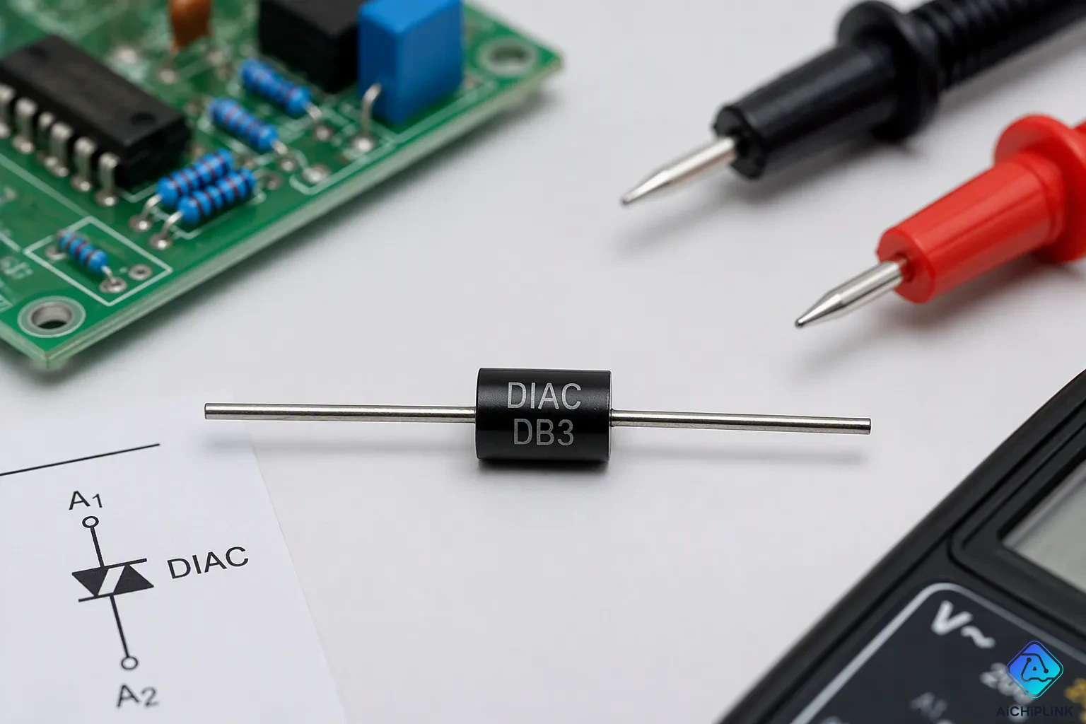
Have you ever wondered how a simple dimmer switch smoothly adjusts a lamp's brightness? The secret lies inside a small electronic part called a diac. This two-terminal device works like a bi-directional semiconductor switch. It lets current flow in both directions, but only when the voltage across it goes past a certain level called the breakover voltage.
This article serves as your introduction to DIACs, offering a clear starting point for understanding their role in modern electronics. You will find out about their special symbol and how they are built inside. You will also learn how they work and why they matter in AC power control circuits. Most importantly, you will see how a diac triggers a TRIAC to control power effectively.
Key Takeaways
-
A DIAC is a two-terminal switch that lets current flow in both directions once the voltage goes past its breakover point.
-
Its balanced five-layer design lets it turn on by itself, with no gate terminal needed.
-
DIACs are often used to turn on TRIACs in AC power control circuits, like light dimmers and motor speed controllers.
-
Key specs include breakover voltage (VBO) and holding current (IH), which control how the switch turns on and off.
-
DIACs provide easy and cheap ways to control phase, but they don't work well for high-power or low-voltage DC uses.
Introduction to DIACs: Symbol and Terminals
Before you can understand how a diac functions in a circuit, you need to recognize its symbol and identify its terminals. This introduction to diacs begins with the visual representation you will encounter on schematics.
Recognizing the DIAC Symbol
The symbol shows two diode arrows that point in opposite directions. Think of a normal diode arrow, then add another arrow next to it facing the other way. This layout quickly shows that the device works in both directions. Current can move through the part either way, unlike a regular diode that only conducts in one direction.
The symbol also hints at something key about how the device behaves. Each diode arrow stands for a junction that must break down before current can flow. When you spot this symbol on a schematic, you know the part will block current until the voltage across it hits a certain level. The two arrows also show that the breakdown behavior is the same for both polarities.
The Two Terminals: MT1 and MT2
Unlike a transistor or an SCR, this device has no gate terminal. This absence makes it an uncontrolled component. It cannot receive a signal to turn on. Instead, it switches automatically when the voltage across its terminals exceeds its breakover voltage.
The two terminals carry the names MT1 and MT2, which stand for Main Terminal 1 and Main Terminal 2. These labels highlight the symmetrical nature of the device. Neither terminal holds a special status over the other. You can connect the component in either orientation, and it will work the same way. This interchangeability stands in contrast to transistors, where you must identify the collector, base, and emitter correctly.
This symmetry makes circuit design easier. You do not need to worry about polarity when installing this part. You simply place it in the circuit path, and it responds to voltage conditions regardless of direction.
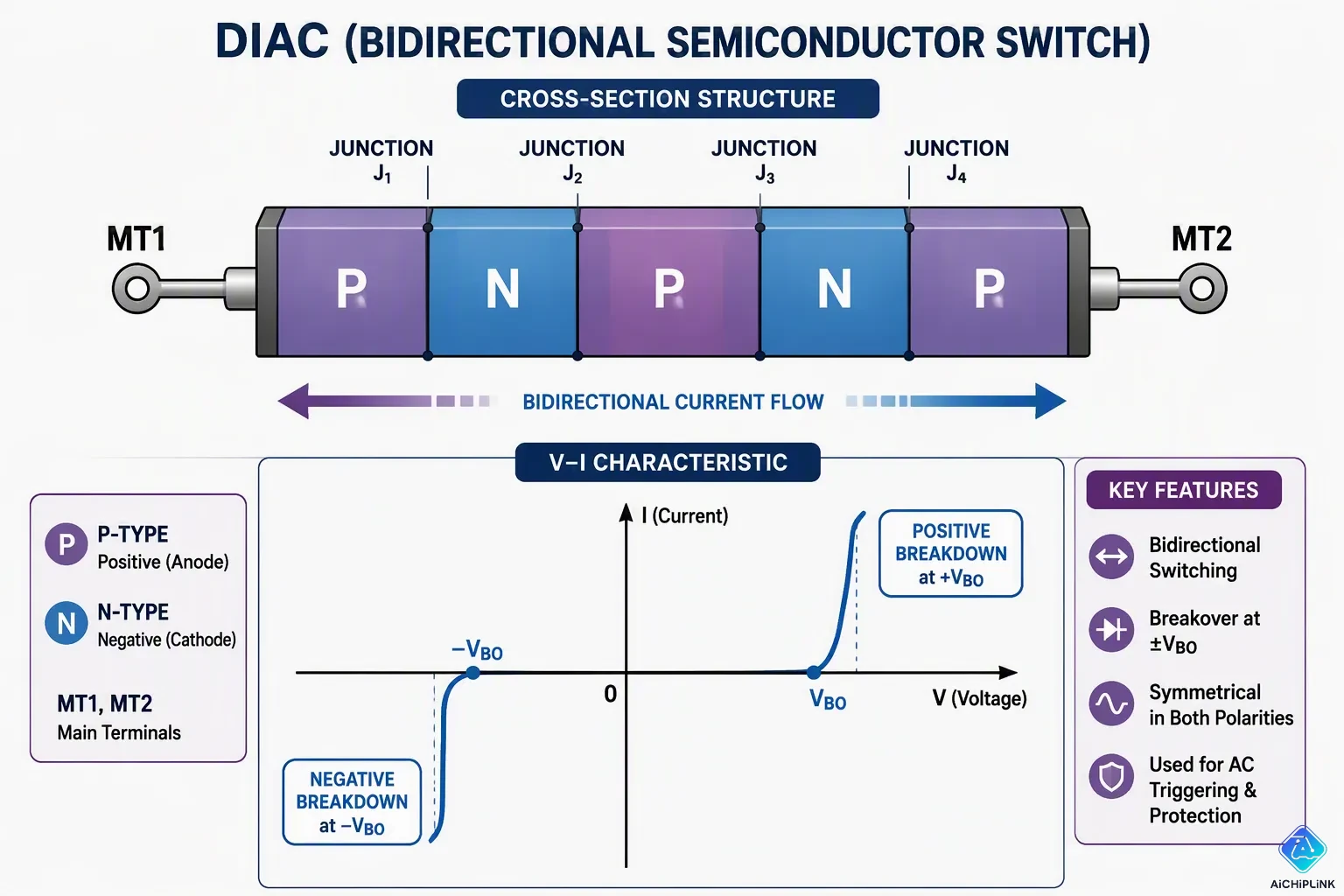
The lack of a gate terminal also means the diac structure stays simple. Inside the package, you find a five-layer semiconductor stack. This setup creates two back-to-back junctions that break down symmetrically. When the voltage rises past the breakover point in either direction, both junctions avalanche at the same time.
For practical purposes, you can think of the diac as a voltage-triggered switch. It waits quietly in its blocking state. It watches the voltage across its terminals all the time. When that voltage crosses the threshold, the diac snaps into conduction. This automatic behavior makes it perfect for triggering other devices at exact moments in an AC cycle.
The two-terminal design also affects how you test and fix these components. You can check one with a multimeter in either polarity. A good unit shows high resistance in both directions until you apply enough voltage. Then it switches to a low-resistance state. This simple test helps you confirm whether a suspect diac still works properly.
This introduction to diacs ends with a clear view of the component's external features. You now know this device has no control input. You know it conducts bidirectionally. You know it triggers automatically at a set voltage. These facts form the base for understanding its internal operation and its role in power control circuits.
DIAC Working Principles and Internal Structure
The Five-Layer Semiconductor Structure
You might wonder what lies inside that small package. The diac structure consists of five alternating semiconductor layers. You can arrange these layers as P-N-P-N-P or N-P-N-P-N. This stack creates four junctions between the layers. The symmetrical arrangement gives the device its bidirectional nature. Each half of the structure mirrors the other half perfectly.
Think of the diac structure as two Zener diodes connected back-to-back in series. Each Zener diode has a specific breakdown voltage. When you place them facing opposite directions, you get a component that breaks down symmetrically. This analogy helps you grasp the behavior without diving into complex semiconductor physics. You can visualize the internal operation clearly with this simple model.
The outer layers connect to the two terminals, MT1 and MT2. The inner layers form the junctions that control conduction. This five-layer design differs from a regular diode's two-layer structure. It also differs from an SCR's three-layer arrangement. The extra layers create the special switching behavior you need for AC control. Manufacturers carefully dope each layer to achieve the desired breakover voltage.
Off State, Breakover Voltage, and Conduction
Understanding diac working principles starts with the off state. In this condition, the device blocks current flow. The junctions inside create a high-resistance barrier. You can apply voltage across the terminals, but current will not move through the device. Only a tiny leakage current flows through the junctions.
The blocking continues until the voltage reaches a critical point. This point carries the name breakover voltage, often written as VBO. When the voltage across the terminals exceeds VBO in either polarity, something dramatic happens. The junctions undergo avalanche breakdown. This process releases charge carriers rapidly. The device switches from its high-resistance blocking state to a low-impedance conducting state. The transition happens in nanoseconds.
You might ask what keeps the diac conducting once it turns on. The answer involves a parameter called holding current, or IH. The device stays in conduction as long as the current flowing through it remains above IH. When the current falls below this level, the diac returns to its blocking state. This behavior resembles a latching switch that releases when current becomes too weak.
This behavior matters most when you work with AC power. An AC sine wave naturally crosses zero voltage twice per cycle. Near these zero-crossing points, the current drops below IH. The diac turns off automatically. It resets itself for the next half-cycle. This automatic reset makes the device perfect for repeated triggering in AC circuits. You get consistent performance cycle after cycle.
The diac working principles change slightly when you apply DC voltage. With DC, the device behaves like a Shockley diode. It triggers once and stays on until the current drops below the holding level. With DC, you must interrupt the circuit to reset the device. This distinction matters for circuit designers who work with both AC and DC applications.
The symmetrical breakdown voltage stands as a key feature. Whether you apply positive or negative voltage, the diac breaks down at nearly the same VBO value. This symmetry ensures consistent triggering in both halves of the AC cycle. You get balanced performance without needing to adjust for polarity. This symmetry also reduces harmonic distortion in the output waveform.
Key Characteristics and Specifications
The Symmetrical I-V Curve and Key Parameters
When you look at the current-voltage (I-V) curve of a diac, you will notice symmetry. The curve appears the same in the first and third quadrants. The V-I characteristics form an S-type curve in both quadrants. This shape shows that the device conducts in both directions. It provides balanced switching for each polarity. This symmetry matters for your circuit design. You get steady behavior in both halves of the AC cycle. The device turns on at the same voltage level no matter the polarity.
Three main parameters define how the diac performs. The first is the breakover voltage, or VBO. This voltage triggers the device into conduction. You need to apply a voltage above this level to turn the device on. The second is the holding current, or IH. This current keeps the device in its on state. When the current falls below IH, the device turns off. The third is the on-state voltage drop. This value stays low and steady during conduction. The device keeps a stable voltage across its terminals while carrying current.
Advantages and Disadvantages in Design
The diac offers clear benefits for your designs. Its balanced triggering works well for TRIAC circuits. You get even firing in both positive and negative half-cycles. This balance lowers harmonic distortion in your output. The device also keeps your design simple. You need no complex control circuits to trigger it. The low cost makes it appealing for many uses.
But you face some limits too. The breakover voltage usually falls between 30 and 40 volts. This high voltage restricts use in low-voltage DC circuits. You cannot use the device in circuits that run below this level. It also cannot handle high power levels. The diac serves as a trigger component only. You must pair it with a TRIAC for power applications.
Knowing these points helps you pick the right part. The diac shines in AC power control uses. It does poorly in low-voltage DC circuits or high-power roles. You need to match the device to your specific needs.
Primary Applications and Comparison with Other Thyristors
Triggering TRIACs for AC Power Control
You will find the diac's most important job in AC power control circuits. The diac sits in series with the gate of a TRIAC. An RC network charges a capacitor through a variable resistor. When the capacitor voltage reaches the diac's breakover threshold, the diac fires. This action sends a sharp current pulse into the TRIAC gate. The TRIAC then conducts for the rest of that half-cycle.
You can adjust the variable resistor to change the charging speed. A slower charge delays the firing point. This delay controls the phase angle at which the TRIAC turns on. You get smooth control over power delivery. This principle powers light dimmers and AC motor speed controllers. You turn a knob, and the lamp brightens or the motor speeds up.
The DB3, DB4, and SMDB3 serve as common diac trigger devices. These parts provide a fixed voltage reference for firing TRIACs or SCRs. You will find them in light dimmers, motor controls, and lamp ballasts. Their key specification is the breakover voltage, or VBO. At this voltage, the diac switches from high resistance to low resistance. Current then flows through the device.
You also see diac applications in fluorescent lamp starters. The diac generates the initial discharge needed for lamp ignition. The device also works for pulse generation. Its precise breakdown voltage enables timing pulses in electronic clocks and delay circuits. Some designs use diacs for voltage-to-frequency conversion. The well-defined switching points turn varying voltage levels into frequency-based outputs.
DIAC vs. SCR vs. TRIAC
You need to understand how these three thyristor-family devices differ. An SCR is a unidirectional switch. It conducts current in only one direction. A TRIAC is a bidirectional switch. It conducts current in both directions. A diac is also bidirectional, but it serves a different purpose.
The diac is a trigger component, not a power-handling component. It cannot handle main power flow. Instead, it provides a precise trigger pulse for the TRIAC. You use the diac to fire the TRIAC at the exact moment you choose. The TRIAC then carries the load current.
Think about the roles this way. The TRIAC acts like a powerful switch that controls the load. The diac acts like a precise trigger that tells the TRIAC when to switch. You need both parts for effective phase control. The diac's symmetrical breakdown ensures balanced firing in both halves of the AC cycle. This symmetry reduces harmonic distortion in your output.
These ac control applications rely on the diac's unique properties. The device triggers automatically at its breakover voltage. It needs no gate signal. This simplicity makes it reliable and cost-effective. You will find this combination in countless power control applications. From simple residential dimmers to industrial motor controllers, the diac plays an essential role. You should view it as a fundamental building block in power electronics.
You now understand the diac as a specialized, bidirectional voltage-triggered switch. This uncontrolled device activates automatically at its breakover voltage. Its core function delivers a sharp, symmetrical trigger pulse to a TRIAC. This pulse enables efficient phase control of AC power.
Key characteristics define its behavior. The breakover voltage (VBO) initiates conduction. The holding current (IH) maintains it. Its simple two-terminal structure makes installation straightforward.
Market projections show steady growth for this component. Analysts forecast a 6.1% compound annual growth rate from 2026 through 2033. This expansion reflects rising demand across power control applications.
From simple dimmers to complex motor controllers, the diac proves essential. This introduction to diacs reveals a fundamental building block. You will encounter these applications throughout power electronics. Understanding this small part unlocks mastery of larger systems.

Written by Jack Elliott from AIChipLink.
AIChipLink, one of the fastest-growing global independent electronic components distributors in the world, offers millions of products from thousands of manufacturers, and many of our in-stock parts is available to ship same day.
We mainly source and distribute integrated circuit (IC) products of brands such as Broadcom, Microchip, Texas Instruments, Infineon, NXP, Analog Devices, Qualcomm, Intel, etc., which are widely used in communication & network, telecom, industrial control, new energy and automotive electronics.
Empowered by AI, Linked to the Future. Get started on AIChipLink and submit your RFQ online today!
Frequently Asked Questions
What prevents a diac from conducting below its breakover voltage?
This introduction to diacs shows you that below the breakover voltage, the internal junctions create a high-resistance barrier. Only a tiny leakage current flows. The blocking state continues until the voltage reaches the VBO threshold. The diac then switches to conduction. This behavior supports many AC applications.
Can you use a diac in a DC circuit?
Yes, you can. With DC, the diac behaves like a Shockley diode. It triggers once and stays on until the current drops below the holding level. You must interrupt the circuit manually to reset the device. This limits its applications to specific setups.
How does a diac differ from a TRIAC?
A diac is a trigger component. It handles only small trigger currents. A TRIAC handles main power flow. You use the diac to fire the TRIAC at the precise moment in the AC cycle. This combination enables diac applications like phase control for light dimmers.
What is the typical breakover voltage of a common diac?
Common diacs like the DB3 have a breakover voltage around 30 to 40 volts. This value ensures symmetrical triggering in both directions. You need to select a diac with a VBO that matches your circuit requirements. Many power control applications use this parameter.
What happens to a diac near the zero-crossing point of AC?
Near the zero-crossing point, the current drops below the holding current. The diac turns off automatically. It resets for the next half-cycle. This behavior makes the diac ideal for AC power control applications.