What is the difference between a latch and a flip-flop?
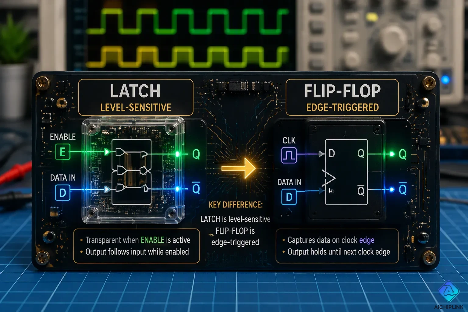
The latch vs flip-flop difference is simple: one is level-triggered and transparent; the other is edge-triggered and only samples its input at clock edges. The level-triggered device works like a door that stays open while the signal is high. The edge-triggered device works like a camera that captures a snapshot at the exact clock edge.
This difference matters because it affects timing, stability, and circuit design. The level-sensitive unit reacts right away, which gives speed but also lets in noise and hazards. The edge-sensitive unit keeps its output steady between edges, so it behaves predictably in synchronized systems. Designers pick the level-sensitive option for fast paths that can handle timing changes; they pick the edge-sensitive option for exact, clock-driven logic.
Key Takeaways
-
A latch is level-triggered and see-through, so its output follows the input while it is turned on.
-
A flip-flop is edge-triggered and reads the input only at clock edges, keeping the output steady between edges.
-
Latches are quick and easy, but they can cause timing problems because they are transparent.
-
Flip-flops give steady timing and work best in synchronous circuits.
-
Use flip-flops for most designs; use latches only when you need specific speed or area.
What Is a Latch?
A latch is a bistable device that stores one bit of data. It keeps that bit as long as power runs through the circuit. Engineers call this a one-bit memory cell, and it is the base for many bigger memory parts in digital systems.
Level-Triggered Operation
A latch is a level triggered device. It watches its data input the whole time its enable signal stays active. While the enable is high, the latch is transparent. That means the output Q just follows the data input D. The moment the enable drops low, the latch stops watching D and remembers whatever value D held at that instant.
A gated D latch uses NAND gates plus an inverter, so its set and reset inputs always stay opposite. While the enable signal is high, those gates pass D straight through to the output. When the enable goes low, the same gates block D, and the internal storage loop keeps Q unchanged. The table below shows this behavior.
| Enable | D | Next Output | Behavior |
|---|---|---|---|
| 0 | X | Holds previous value | Hold |
| 1 | 0 | 0 | Reset |
| 1 | 1 | 1 | Set |
Here, X means the data input does not affect the output. This level-sensitive behavior defines the gated D latch.
Why Latches Are Fast and Simple
A latch reacts to its input right away. It does not wait for a clock edge. That direct path makes it faster than edge-triggered alternatives, and it needs fewer gates to build. Level-sensitive transparent latches also take less silicon area, which saves cost in large designs.
Designers often choose level-sensitive latches for asynchronous circuits. These circuits have no global clock, so speed matters more than strict timing control. A latch fits that job well because it responds the moment its enable signal changes. The trade-off is that a transparent latch lets input changes flow to the output during the entire enable window. Noise or glitches on the data line can pass through. Engineers accept that risk when raw speed outweighs tight timing discipline.
What Is a Flip-Flop?
A flip-flop is a bistable device that stores one bit, just like a latch. The main difference is what makes it trigger. In digital electronics, a flip-flop only updates its output at a clock edge. That edge can be rising or falling. This makes it an edge triggered device, not a level-sensitive one.
Edge-Triggered Operation
Think of a camera. A camera takes a snapshot at one moment. A flip-flop works the same way. On the rising clock edge, it captures the value on D. The D input must stay steady during the setup-and-hold window around that edge. After the active edge, the output Q changes to the sampled D value after the clock-to-Q propagation delay. Until the next rising edge, Q stays the same. Changing D while the clock is high, low, or falling does not affect the stored value. This rule is written as Q(t+1)=D.
The table below shows the three timing parameters for a positive edge-triggered D flip-flop.
| Timing parameter | Definition |
|---|---|
| Setup time | Minimum duration input data must be stable before the active clock edge. |
| Hold time | Minimum duration input data must remain stable after the active clock edge. |
| Clock-to-Q delay | Propagation delay from the active clock edge until the output reflects the new value. |
Better Timing Control
Edge-sensitive flip-flops cut down timing hazards in sequential circuits. A transparent latch lets a value feed back through combinational logic and re-enter while enabled. This race-around condition makes the result depend on pulse duration. An edge-triggered flip-flop samples its input only at a clock edge. It captures the value at that instant and ignores further changes for the rest of the cycle.
Engineers build the standard edge-triggered register as a master-slave setup. Two opposite-enable D latches sit in series. The master captures D on the rising edge while the slave holds the previous output. Then the slave releases the new value to Q. This stops a pipeline stage from passing data straight through the stage. For a pipeline path, the clock period must meet clock-to-Q plus worst-case combinational delay plus setup time. This makes sure the next edge-triggered stage gets a stable input. These memory elements form the backbone of synchronous sequential logic.
Latch vs Flip-Flop: The Core Difference
The Difference Between Flip-Flop and Latch
The difference between flip-flop and latch comes down to when the device accepts new data. A gated D latch is level-sensitive. It stays transparent whenever its clock or enable input is high, so Q follows D the whole time. An edge-triggered D flip-flop is edge-sensitive. It samples D only at the rising clock edge and freezes Q between edges. This single distinction drives every other contrast in a latch vs flip-flop comparison.
| Aspect | Gated D Latch | Edge-Triggered D Flip-Flop |
|---|---|---|
| Sensitivity | Level-sensitive | Edge-sensitive |
| Transparent condition | Transparent whenever CLK = 1; Q follows D | Not transparent; Q only changes at the rising edge of CLK |
| Behavior when CLK = 1 | Q follows D, so changes in D pass directly to Q | Q remains frozen between edges regardless of D changes |
| Behavior when CLK = 0 | Q holds its last value | Q holds its last value |
| Main issue | Transparency hazard: if D changes while CLK = 1, Q changes too | Avoids transparency hazard by sampling D at one instant |
| Design role | Simpler storage element, but unsuitable for predictable synchronous capture | Samples D once per clock cycle, enabling predictable synchronous design and static timing analysis |
| Internal basis | 4 NAND gates; passes D when enabled | Master-slave structure using two gated D latches with inverted clocks; master and slave are never simultaneously transparent |
The internal basis row explains the deeper difference between a latch and a flip-flop. A master-slave D flip-flop uses two D latches. The master latch accepts D while the clock is high, and the slave latch stays isolated. When the clock goes low, the master stops accepting data and the slave transfers the stored value to the output. The output can only change at that clock transition, so the circuit becomes edge-triggered rather than level-sensitive. This arrangement converts level-sensitive behavior into edge-triggered behavior.
Transparency and Timing Hazards
Transparency creates real design problems. While a latch is transparent, the combinational logic and the latch form a combinational cycle. The logic computes a state bit, the state bit passes through the open latch, and the logic computes another state bit. Signals circulate at an uncontrolled rate. This is why engineers rarely use latches directly as memory in synchronous sequential circuits.
Edge-triggered flip-flops avoid this risk. Their window of change is instantaneous. The remembered value can propagate through combinational logic to compute the next value to store without the danger of that new value feeding back into the latch before the window ends. A master-slave flip-flop cascades two latches with opposite clock-phase values, so for each clock value exactly one latch is transparent and the other holds its value.
Several timing hazards follow from latch transparency:
-
When the enable signal is active, the latch is transparent and its output follows the input. This transparency can cause glitches or race conditions if inputs change during the enable period.
-
Because latches are sensitive to the level of the clock, timing control is more difficult compared to edge-triggered flip-flops. This can lead to timing hazards and makes designing synchronous systems more complex.
-
Due to their transparency and level sensitivity, latches are more susceptible to noise and glitches on the input or enable signals.
-
Using latches in large synchronous systems can complicate timing analysis and increase the risk of errors.
A level-triggered JK latch with J=K=1 shows the worst case. The output can toggle, feed back to the input gates while the clock is still high, and toggle again repeatedly, producing uncontrolled oscillation. An edge-triggered JK flip-flop avoids this because it samples J and K only at the clock edge. By the time the output changes and feeds back, the sampling window has already closed, so only one state change occurs per clock event. This contrast between flip-flops and latches explains why modern sequential design favors edge-triggered storage.
The Difference Between Latch and Flip Flop in Timing
Setup and Hold Times
Timing rules set these two storage elements apart. A flip-flop needs a strict setup and hold window around the active clock edge. The data input must stay steady for a set time before the edge and stay steady for a set time after it. If data changes inside that window, the output may become hard to predict. This strict rule makes static timing analysis possible for synchronous designs.
A latch works in a different way. It does not have a setup-and-hold window tied to an edge. Instead, the latch is transparent for the whole active level of the enable or clock signal. Data can show up at any point during that window and still reach the output. The only timing rule is that data must be steady before the enable falls low. This looser rule gives the latch an edge in raw speed.
The difference between latch and flip flop in timing shows up clearly in pipeline design. A flip-flop stage must finish its combinational logic before the next clock edge minus the setup time. A latch stage can borrow time from the next stage. Designers call this cycle-borrowing to gain more setup time. The latch opens earlier in the cycle, so the logic has a longer effective window to settle. This method helps when one pipeline stage has more delay than others.
When Each One Fits Best
The choice depends on the design goals. A latch vs flip-flop decision often comes down to speed versus predictability. A latch fits best in asynchronous paths, high-speed custom blocks, and small storage elements where area and delay matter most. A flip-flop fits best in synchronous sequential circuits that rely on a single clock signal for coordination. Most field-programmable gate arrays and standard cell libraries provide flip-flops as the main storage element because they make timing closure simpler.
A sequential design with tight clock discipline almost always uses edge-triggered storage. The designer can work out the worst-case path delay and set the clock period to match. A latch-based design needs more careful analysis because transparency lets signals race through combinational logic during the open window. That race can cause hold violations or unexpected state changes.
Engineers sometimes mix both elements in one design. They use latches on critical paths to steal time and flip-flops everywhere else for stability. This hybrid approach demands careful verification. The difference between flip-flop and latch timing behavior means each element needs its own constraint set. A tool that checks only edge-triggered rules will miss latch transparency hazards. A strong timing methodology accounts for both.
In practice, the safest rule for beginners is simple. Use flip-flops for synchronous logic. Use latches only when a specific speed or area problem justifies the extra analysis. That habit keeps sequential circuits predictable and easy to verify.
Common Types and Applications
SR Latch and D Flip-Flop
These two parts are basic memory cells. An SR latch uses cross-coupled NAND gates to hold one bit. It uses active-low Set (S') and Reset (R') inputs.
| S' | R' | State | Behavior |
|---|---|---|---|
| 1 | 1 | Hold | Outputs keep previous state |
| 0 | 1 | Set | Q forced to 1 |
| 1 | 0 | Reset | Q forced to 0 |
| 0 | 0 | Forbidden | Outputs forced to 1; unstable |
This latch vs flip-flop comparison in the circuit and truth table shows a key contrast. The latch responds to signal levels while its enable is active. The D flip-flop responds only to an edge. A positive edge-triggered register uses a master-slave setup. The master stage samples D while the clock is low. The slave stage holds the previous output. When the clock rises, the master stops sampling, and the slave copies the new value to Q. Q changes once per clock cycle.
Engineers link D flip-flops to build shift registers and counters. In a shift register, one stage's output feeds the next stage's input. Each clock pulse shifts bits one position. This lets a digital microcontroller read many sensors with fewer pins. A ring counter forms when the last stage's output feeds back to the first input. A 1 bit travels around the loop with each clock pulse.
Asynchronous vs. Synchronous Use
Latches appear in asynchronous circuits because they react right away to an enable signal. They allow time borrowing in timing analysis. Latches and flip-flops serve different design goals. Flip-flops dominate synchronous sequential circuits because a clock signal gives exact control. Edge triggering samples input only at a transition. That stops race conditions and glitches.
Real-world uses show the difference. A simple two-gate circuit can keep an alarm flag on until a controller clears it. It can also turn a momentary switch into a toggle switch for power control. Registers and memory circuits depend on exact edge-triggered storage. Engineers match the storage part to the design's timing needs.
A latch is level-triggered and transparent during a high signal; a flip-flop is edge-triggered and holds its value between edges. One is like an open door; the other, like a camera, snaps at the edge.
The latch vs flip-flop choice guides every design decision. Timing differences between the two parts shape how engineers build sequential circuits. Asynchronous paths, where speed matters, suit a latch. Synchronous designs needing stable and predictable storage fit a flip-flop well.
Use a latch for fast, timing-flexible work. Use a flip-flop for reliable sequential logic.
This practice keeps circuits sturdy and easy to check.

Written by Jack Elliott from AIChipLink.
AIChipLink, one of the fastest-growing global independent electronic components distributors in the world, offers millions of products from thousands of manufacturers, and many of our in-stock parts is available to ship same day.
We mainly source and distribute integrated circuit (IC) products of brands such as Broadcom, Microchip, Texas Instruments, Infineon, NXP, Analog Devices, Qualcomm, Intel, etc., which are widely used in communication & network, telecom, industrial control, new energy and automotive electronics.
Empowered by AI, Linked to the Future. Get started on AIChipLink and submit your RFQ online today!
Frequently Asked Questions
Can a latch replace a flip-flop in a design?
Sometimes it can, but not always. A latch works well in asynchronous paths where speed is important. A flip-flop fits synchronous designs that need stable, edge-triggered storage. Swapping one for the other changes the timing rules. Engineers must recheck setup, hold, and transparency hazards before making the swap.
Why do latches cause more timing problems than flip-flops?
A latch stays transparent while its enable is active. Input changes flow straight to the output during that window. Noise and glitches can pass through. A flip-flop samples its input only at a clock edge. That single instant of capture blocks most race conditions and makes timing analysis simpler.
Are flip-flops built from latches?
Yes. A master-slave flip-flop uses two gated D latches in series with opposite clock phases. The master captures data on one phase. The slave releases it on the other. This setup turns level-sensitive behavior into edge-triggered behavior. The two latches are never transparent at the same time.
Which one should a beginner use?
Beginners should start with flip-flops for most sequential logic. They make timing closure easier and act predictably under a single clock. Latches suit specific speed or area problems. Those cases need extra analysis. A simple rule: use flip-flops by default, and reach for latches only when a clear reason exists.
Do latches and flip-flops store data differently?
Both store one bit using a bistable loop. The difference lies in when they accept new data. A latch accepts data the whole time its enable is active. A flip-flop accepts data only at a clock edge. After that edge, the flip-flop holds the value until the next edge arrives.