What Is the Difference Between Monostable and Astable Circuits?
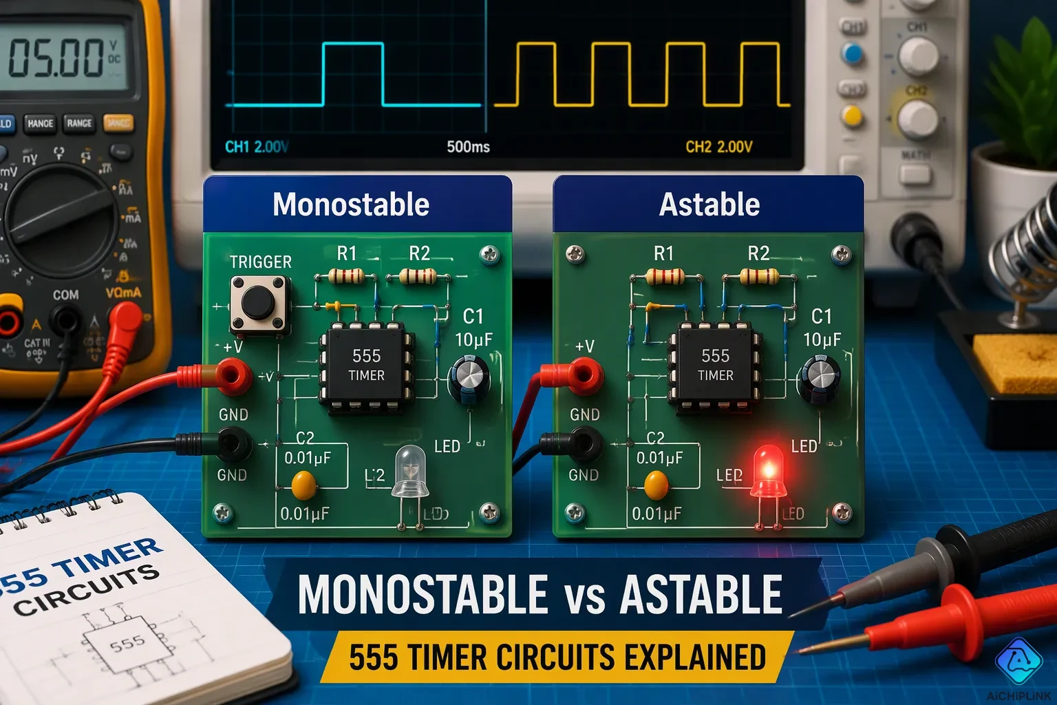
Think of a doorbell. You push the button once, and it rings for a moment. Now think of a blinking LED on a robot. It turns on and off, over and over, with no button press at all.
That difference between monostable and astable circuits shows they are not the same. A monostable circuit makes one pulse when triggered. An astable circuit keeps switching between two states without any trigger. Both are basic types of multivibrators, but they act in opposite ways.
You will learn how each circuit works, compare them side by side, and choose the right one for your project.
Key Takeaways
-
A monostable circuit gives one pulse when it is triggered. After that, it goes back to its resting state.
-
An astable circuit keeps switching between high and low without stopping. It doesn't need a trigger to begin.
-
Use a monostable circuit for one-time jobs like cleaning up button presses or making short waits.
-
Use an astable circuit for steady oscillation, like blinking LEDs or making clock signals.
-
The 555 timer chip can work in two ways. Build both circuits to see how they are different.
What Is a Monostable Multivibrator?
A monostable multivibrator is a circuit that has only one stable state. It stays calm in that state until something triggers it. The name comes from that single resting condition. Without a trigger, the circuit stays put forever.
How a Monostable Circuit Works
The circuit holds its stable starting state until an outside trigger pulse arrives. That pulse moves the output into an unstable state, where it remains for a set time decided by internal timing parts. After that time ends, the circuit returns to its stable state by itself. No second trigger is needed.
A resistor and capacitor usually set the timing. In a 555 timer monostable, the output stays low until a negative-going pulse hits the trigger pin. The output then goes high, and the capacitor charges through the resistor. When the capacitor voltage reaches about two-thirds of the supply, the circuit resets. The pulse width follows T = 1.1 × R × C, where T is in seconds, R is in ohms, and C is in farads. The trigger pulse width does not change the output width.
In a MOSFET-based monostable circuit, resistor R and capacitor C form an RC timing circuit. In the stable state, the capacitor's voltage keeps the N-channel enhancement-mode MOSFET switched ON, and the LED connected to its drain is also ON. When a switch is closed, the capacitor is short-circuited and discharges, the MOSFET's gate is grounded, and both the MOSFET and LED turn OFF.
Because each trigger yields one pulse, engineers call it a one-shot multivibrator. A retriggerable monostable can restart its timing period if a new trigger signal arrives mid-cycle.
Common Uses of a Monostable Circuit
You will find this multivibrator circuit wherever a single pulse or a delay is useful. Push buttons on keyboards and calculators bounce when pressed, and that chatter can look like many presses. Feeding the noisy signal into a monostable produces one clean pulse longer than the bounce, so the logic sees a single press.
Delay and timing tasks fit the same pattern. An automatic faucet triggers water flow for a set time, then shuts off. A darkroom timer or hallway light works the same way. The time constant of the RC network decides how long the output stays high.
What Is an Astable Multivibrator?
An astable multivibrator has no stable state at all. It flips between two unstable states forever, as long as power is supplied. One moment transistor TR1 is OFF and TR2 is ON; the next moment they swap roles. The circuit never settles into one condition.
The Astable Multivibrator is another kind of cross-coupled transistor switching circuit that has NO stable output states because it keeps changing from one state to the other all the time.
This action makes the astable multivibrator a free-running multivibrator. It needs no outside trigger to start or keep going. The circuit is not steady in either state, so it oscillates by itself.
How an Astable Circuit Works
The cycle starts when TR1 turns ON. Its collector voltage falls, which sends a quick negative voltage swing to the base of TR2 and turns it fully OFF. Capacitor C1 then charges the other way through resistor R3, pushing the base of TR2 positively toward Vcc. Once the base of TR2 reaches about 0.6V, TR2 turns fully ON into saturation. That action begins the process again with capacitor C2 pulling the base of TR1 negative. This cycle repeats nonstop whenever supply voltage is present.
In a 555 timer astable circuit, the timing capacitor charges through R1 and R2 but discharges through R2 only. The capacitor voltage swings between 1/3 Vcc and 2/3 Vcc. When it reaches 2/3 Vcc, the output goes LOW and the capacitor discharges. When it drops to 1/3 Vcc, the output goes HIGH again. This repeated charging and discharging makes the circuit a free-running oscillator that keeps producing square waves. The time constant set by the resistors and capacitor controls the frequency. With equal timing resistors, the output duty cycle is about 66% ON and 33% OFF.
Common Uses of an Astable Circuit
You will find the astable multivibrator oscillator in many everyday devices. It works as a clock generator, making square waves for clock pulses and signal modulation in digital circuits. It also serves as a clock divider in communication systems.
| Application Area | Typical Use |
|---|---|
| Clock generators | Square waves for clock pulses and signal modulation |
| Timers | Delay timers, interval timers, and PWM for motor speed or LED brightness |
| Audio oscillators | Tone generators in alarms, buzzers, and simple music synthesizers |
Each pulse from the circuit drives a different task. The same steady oscillation that blinks an LED can also set the beat for a digital system.
Key Differences Between Monostable and Astable
You now know how each circuit type works on its own. When you put them side by side, the difference between monostable and astable circuits becomes obvious. Each multivibrator has its own job, and the table below shows exactly where they differ.
| Attribute | Monostable Circuit | Astable Circuit |
|---|---|---|
| Number of Stable States | 1 stable state (plus 1 quasi-stable state) | 0 stable states (only quasi-stable states) |
| Operating Behavior | Needs an outside trigger to leave the stable state, then goes back to it on its own | Keeps switching between HIGH and LOW without ever stopping |
| Trigger Requirement | Needs one outside trigger pulse to make one output pulse | No outside trigger needed; runs freely |
| Output | One timed pulse per trigger | Continuous square/rectangular wave |
| Timing Control | RC network sets the pulse width | RC network sets the oscillation frequency |
| Stability | Semi-stable (returns to stable state after pulse) | Least stable (always switching) |
Triggering and Stability
The way these two multivibrators trigger is what separates them most. A monostable multivibrator sits quietly in its stable state. You have to send a trigger pulse to start a cycle. That trigger uses edge triggering, usually a falling edge, not level triggering. The circuit reacts to the signal change, not to the signal level. A qualifying edge breaks the balance and starts the internal RC timing process. The output pulse width depends on the circuit's own RC timing parts, not on the trigger pulse width. Even a long trigger signal makes only one fixed-width pulse. The circuit triggers once at the active edge, sends out its pulse, then goes back to steady state.
An astable multivibrator does not need that kind of attention. It runs freely or triggers itself. The circuit has no stable state at all. It holds two quasi-stable states, HIGH and LOW, and switches between them automatically at a set interval. You supply power, and the oscillation starts. No button press, no outside signal, no help needed. The circuit never settles because it cannot settle. This key difference between monostable and astable circuits decides how you use each one in a project.
Output Waveforms and Applications
The output waveforms show the same idea from another view. A monostable multivibrator makes one high pulse after triggering, then goes back to low after a set time. External resistor and capacitor values set the pulse duration. You get exactly one shot per trigger. This one-shot multivibrator behavior fits jobs like debouncing switches, making precise delays, or shaping irregular input events into regular, predictable output pulses.
An astable multivibrator makes a repeating square wave that keeps switching between high and low. External resistors and capacitor set the frequency and duty cycle. The output never stops. This free-running multivibrator works as an oscillator circuit, oscillating at a certain frequency. You see this behavior in clock generators, tone generators, and LED flashers.
The 555 timer shows both modes clearly. In monostable operation, the timer makes a single output pulse when triggered, with the pulse width set by an external resistor and capacitor. In astable operation, the timer keeps switching the output between high and low as the capacitor charges and discharges, making an ongoing square wave whose frequency and duty cycle depend on the external component values.
Remember the main difference: a monostable multivibrator has one stable state and needs a trigger, while an astable multivibrator has no stable state and oscillates continuously. The astable circuit is never stable in either state. Choose monostable for one pulse per event. Choose astable for continuous oscillation.
Choosing the Right Circuit for Your Project
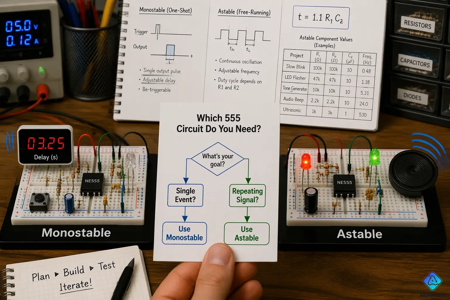
You now know how each circuit acts. The next step is choosing the right one for your build. This choice comes down to one question: do you need a single event or a repeating signal? Your answer leads you to the correct multivibrator every time.
When to Use a Monostable Circuit
Pick a monostable multivibrator when you need one event to happen for a set time after a trigger. The output stays LOW while resting. A trigger pulse sends it HIGH for a set time, then it goes back LOW and waits. If another trigger comes while the output is still HIGH, the circuit ignores it.
This monostable setup works for time-delay and single-pulse jobs. A time-delay relay driver is a classic example. You can figure out the delay with t = 1.1 R1 C2, where t is in seconds, R1 is in ohms, and C2 is in farads. Bigger resistor and capacitor values give a longer HIGH time.
Other good fits include edge detection, system reset control, signal debouncing, pulse stretching, and glitch removal. A darkroom timer, a hallway light, or an automatic faucet all depend on this one-shot behavior. Choose monostable when one trigger should make exactly one pulse of fixed width.
When to Use an Astable Circuit
Choose an astable multivibrator when you need a steady oscillation or repeated pulses. This circuit has no stable state. It switches HIGH and LOW forever once you apply power. No trigger is needed.
An astable multivibrator oscillator works for LED flashers, tone generators, clock signals for digital circuits, and pulse width modulation. A basic metronome or alarm siren also fits here. The table below shows real component values for common astable projects.
| Application | R1 | R2 | C | Frequency |
|---|---|---|---|---|
| Fast LED Flasher | 10kΩ | 10kΩ | 0.1µF | ≈ 480 Hz |
| Audio Tone Generator | 1kΩ | 10kΩ | 0.01µF | ≈ 6.5 kHz |
| Slow Blinking LED | 47kΩ | 100kΩ | 10µF | ≈ 0.48 Hz |
One limit matters here. In the standard astable circuit, you cannot adjust on time and off time on their own. The capacitor charges through R1 and R2 but discharges only through R2. Add a diode across R2 to fix this. Then R1 mainly sets on time and R2 mainly sets off time.
The 555 timer works in both modes, so it makes a great learning tool. Build the monostable circuit first. Trigger it with a push button and watch the single output pulse. Then rebuild it in astable mode and watch the LED blink on its own. This hands-on test makes the difference between monostable and astable circuits clear in minutes.
For astable builds, respect the LM555 practical frequency limit of about 1 MHz. Use an operating voltage between 4.5 V and 15 V, with 9 V a common choice. The output can sink or source around 200 mA, so it drives small loads directly. Higher loads may need a transistor. Account for component tolerances and temperature effects, then refine your values through prototype testing.
The difference between monostable and astable circuits rests on one core idea. A monostable multivibrator generates a single output pulse when you trigger it. An astable multivibrator runs freely, producing continuous oscillation without any external signal.
Choose monostable when your project needs one timed response to an event. Choose astable when you need a repeating waveform. Your project goal guides that decision.
Build both circuits with a 555 timer to see the difference firsthand. Trigger the monostable with a button and observe one pulse. Then switch to astable mode and watch the LED blink on its own. This hands-on experiment will make the concept stick.

Written by Jack Elliott from AIChipLink.
AIChipLink, one of the fastest-growing global independent electronic components distributors in the world, offers millions of products from thousands of manufacturers, and many of our in-stock parts is available to ship same day.
We mainly source and distribute integrated circuit (IC) products of brands such as Broadcom, Microchip, Texas Instruments, Infineon, NXP, Analog Devices, Qualcomm, Intel, etc., which are widely used in communication & network, telecom, industrial control, new energy and automotive electronics.
Empowered by AI, Linked to the Future. Get started on AIChipLink and submit your RFQ online today!
Frequently Asked Questions
Can a monostable multivibrator trigger itself?
No. A monostable multivibrator needs an outside signal to leave its stable state. It cannot start on its own. You must send a trigger pulse to begin each cycle. After the set time ends, the circuit returns to rest and waits for the next trigger.
What happens if you never trigger a monostable circuit?
Nothing changes. The circuit stays in its stable state forever. The output remains at its resting level. No pulse appears at the output pin. You get action only when you apply a trigger signal.
Does an astable multivibrator need a clock signal to run?
No. An astable multivibrator runs freely once you apply power. It generates its own continuous square wave. The RC timing network sets the frequency. You do not need any external clock or trigger source to keep it oscillating.
Can you change the output pulse width of a monostable circuit?
Yes. The RC network sets the pulse width. A larger resistor or capacitor value gives a longer output pulse. You can swap these parts to match your timing needs. The trigger signal itself does not change the pulse width.
Which multivibrator type works best for blinking an LED?
An astable multivibrator works best for this task. It switches HIGH and LOW on its own. The LED blinks without any button press. A monostable circuit gives only one pulse per trigger, so the LED would flash once and stop.