Top 10 Oscillator Circuit Examples for Your Electronics Projects
You need reliable oscillator circuits for almost every electronics project. The global market for these parts reached 5.56 billion dollars in 2025. Experts predict steady growth to 9.38 billion by 2034. This growth shows how important oscillators have become in many industries.
This list shows ten practical oscillator circuit designs you can build today. Each entry tells you what the circuit does, how it works, and where to use it. You'll find options from simple audio generators to precise frequency sources for communication systems.
Use this collection as your starting point. Try different designs, compare their performance, and find the oscillator that fits your project best.
Key Takeaways
-
Oscillators make signals that repeat over and over. They are very important for lots of electronics projects.
-
Pick a crystal oscillator when you need exact timing. It gives the most steady frequency.
-
You can use an RC oscillator to create simple audio tones. It is easy to build and works at low frequencies.
-
Choose an LC oscillator for radio frequency (RF) uses. It lets you adjust the frequency.
-
Begin with a 555 timer circuit. It is easy and perfect for learning how oscillators work.
Understanding Harmonic Oscillator Circuits
Harmonic oscillators create a clean sine wave signal that repeats. The math uses sine and cosine functions to describe the wave's amplitude, frequency, and period. These circuits use resonant networks made from resistors and capacitors or inductors and capacitors. The resonant network decides the frequency and shapes the output.
RC Phase Shift and Wien Bridge Oscillators
Resistor-capacitor oscillators make sine waves at low frequencies. The RC phase shift oscillator uses three RC stages to create the phase shift needed for oscillation. This rc oscillator circuit works from a few hertz up to several kilohertz. You can use it for audio testing and simple tone generation. The total harmonic distortion (THD) is between 0.5% and 2% for a three-stage design. This means the output has some distortion but is still okay for many uses.
The Wien bridge oscillator performs much better. This circuit gets a THD between 0.01% and 0.1% with modern parts. In the best case, you can reach 0.0003% distortion. But using diode-based amplitude control raises THD to 1-5%. One builder reported 0.002% THD in practice. The Wien bridge is great for low-distortion sine waves, like audio signal generators and lab test gear. You change the frequency by adjusting two matched resistors or capacitors at the same time.
LC-Based Oscillators (Colpitts, Hartley, Clapp)
LC oscillator circuits use inductors and capacitors to create resonance at radio frequencies. The Colpitts oscillator uses a capacitive voltage divider in its feedback network. The Hartley oscillator uses an inductive divider instead. The Clapp oscillator adds an extra capacitor in series with the inductor for better stability. These designs work well in RF applications, from hundreds of kilohertz to hundreds of megahertz.
The frequency stability of an lc oscillator circuit is about ±0.1%. This is less than crystal oscillators, which get ±10 ppm stability. But LC oscillators can be tuned, which crystals cannot. You can adjust the frequency by changing a variable capacitor. The THD for LC oscillators is between 1% and 3%. This works for RF applications because the output goes through filtering stages. Choose an LC design when you need adjustable frequency in the RF range and can accept moderate distortion.
Exploring Crystal Oscillator Circuits
Crystal oscillators are the best for keeping a steady frequency. These circuits use a quartz crystal to make the signal. When you add voltage, the crystal vibrates at a set speed. This vibration creates an electrical signal that is very exact. Quartz oscillators hold their frequency better than RC or LC circuits. You will find them in almost every device that needs exact timing.
High-Frequency Crystal Oscillator Circuit
A high-frequency crystal oscillator circuit usually works at 10 MHz. This circuit is the main clock for many microcontrollers. Families like PIC, AVR, STM32, and ARM need this stable signal. The circuit also gives a baud rate reference for UART, RS-232, and RS-485 communication. You can use it in counters, timers, and measurement tools that need a precise frequency.
Frequency tolerance tells you how much the actual frequency differs from the set value at 25°C. A 10 MHz crystal with ±50 ppm tolerance could be anywhere from 9.9995 MHz to 10.0005 MHz. This difference matters for communication systems that need exact timing.
The table below shows common uses for crystal oscillator circuits:
| Application Category | Specific Devices | Key Function |
|---|---|---|
| Consumer timing | Digital clocks, watches, timers | Uses Pierce Oscillator setup to keep time |
| Processor clocking | Microprocessors, micro-controllers, Arduinos, PICs, CPUs | Makes clock waveform for running instructions |
This high-frequency crystal oscillator circuit gives a clean clock signal for digital logic. You can build it with just a few parts: the crystal, two capacitors, and an inverter gate. The output connects directly to the microcontroller's clock input.
Low-Frequency Crystal Oscillator Circuit
A low-frequency crystal oscillator circuit runs at a frequency suitable for real-time clocks, as it divides down easily to a one-second pulse. Real-time clocks (RTCs) in computers, watches, and appliances use this design. The low frequency uses very little power, so it is great for battery devices.
Crystal oscillator modules in this range use microamps of current. You can leave them running for years on a small battery. The circuit uses the same Pierce setup as the high-frequency version. The main difference is the crystal's size and the capacitor values.
This high-precision oscillator circuit stays accurate even when temperature changes. You can use it to keep exact time in data loggers, alarm systems, and medical devices. The low-frequency output also works as a low-power wake-up timer for sleep-mode microcontrollers.
Both crystal oscillator modules share the same design ideas. Pick the high-frequency version for processing tasks. Pick the low-frequency version for timekeeping and power-sensitive uses.
Exploring Relaxation and Specialized Oscillator Types
Relaxation Oscillators and the 555 Timer
Relaxation oscillators make non-sine wave shapes using a timing capacitor and a threshold. These circuits create triangle, square, and sawtooth waves. There are two main types: sawtooth kinds with one ramp per cycle, and astable multivibrators with two ramps per cycle. These designs fit audio uses, like blinking lights, electronic beepers, and function generators.
The 555 timer is the most common relaxation oscillator chip. Set it in astable mode to make square wave circuits. The basic astable 555 uses two resistors and one capacitor. The capacitor charges through R1 plus R2. It discharges through R2 only. This gives a duty cycle usually above 50 percent. The frequency formula is f equals 1.44 divided by R1 plus two times R2 times C. This frequency works for audio uses.
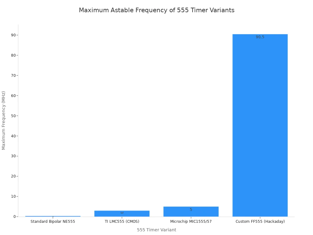
The top frequency depends on the 555 type. A standard bipolar NE555 hits 350 kHz. This needs a direct feedback link without RC parts. The TI LMC555 CMOS version hits 3 MHz. The Microchip MIC1555 hits 5 MHz.
You can use relaxation oscillators as clock sources for digital systems. The output gives a timing reference. They work for PWM by changing the duty cycle. Switching power supplies also use them to control power transistors.
Ring, VCO, and Multivibrator Circuits
A ring oscillator uses an odd number of inverter gates in a loop. The frequency depends on the delay of each gate. With three gates and a 60 ns delay per gate at 5V, the result is about 2.77 MHz. Measured values range from 18.5 MHz to 39.5 MHz, with higher voltage raising the rate. Integrated circuits use ring oscillators for clock signals.
A voltage-controlled oscillator changes its frequency based on an input voltage. Tuning range, tuning gain, and phase noise are key features. Manufacturers support uses across a wide frequency range, found in phase-locked loops and frequency synthesizers.
A multivibrator circuit makes clock pulses for digital logic. The astable multivibrator gives a steady square wave output. This oscillator works as a clock source for counters and timers.
How to Choose the Right Oscillator
Picking the right oscillator for your project does not have to be hard. You just match the circuit to what you need. Start by asking what the oscillator must do. Do you need a clock signal for a microcontroller? Do you want an audio tone for an alarm? Or do you need a precise frequency for a radio transmitter? Each job points to a different design.
Matching the Circuit to Your Needs
Your first step is to decide the output waveform. Harmonic oscillator circuits make clean sine waves. Relaxation circuits make square, triangle, or sawtooth shapes. Digital logic needs square waves. Audio testing needs low-distortion sine waves. The waveform you need narrows down your choices right away.
Next, think about the frequency range. A high-frequency crystal oscillator circuit works well for microcontrollers and communication systems. An RC oscillator circuit handles audio frequencies from a few hertz to several kilohertz. LC designs cover the radio frequency range from hundreds of kilohertz to hundreds of megahertz. Pick the circuit's natural range to match your project's needs.
Also think about your power budget. Battery-powered devices need low current draw. Crystal oscillator modules are great here, using only microamps of current. RC circuits use more power. LC designs fall in between. For a wearable device that must run for months, a low-frequency crystal oscillator circuit makes sense. For a bench-top test instrument plugged into the wall, power matters less.
The table below shows the main trade-offs:
| Oscillator Type | Frequency Stability | Power Consumption | Best Application |
|---|---|---|---|
| RC Oscillator | Moderate stability | Higher power | Audio tones, simple timing |
| LC Oscillator | ±0.1% | Moderate power | RF signal generation |
| Crystal Oscillator | ±10 ppm (0.001%) | Very low power | Precision timing, RTCs |
Considering Frequency, Stability, and Waveform
Frequency stability tells you how much the output drifts from its set value. RC oscillators have variation because resistors and capacitors change with temperature and manufacturing tolerances. Their stability is limited, typically much lower than crystal oscillators. LC oscillators achieve about 0.1% stability. A crystal oscillator circuit achieves the best stability, typically ±10 ppm (0.001%). For a high-precision oscillator circuit used in GPS or telecommunications, crystal is the only sensible choice.
Waveform purity matters for some uses. Harmonic oscillator circuits make sine waves with low distortion. The Wien bridge reaches total harmonic distortion between 0.01% and 0.1%. LC oscillators make sine waves with 1% to 3% distortion, which is fine for RF because filtering stages clean the signal. Relaxation oscillators make non-sinusoidal waveforms like square or triangle waves. These work for digital timing but not for audio or RF uses.
Here is a simple decision path. For precise timing, use a crystal. For a simple audio tone, use an RC oscillator. For RF, use an LC oscillator. For variable frequency controlled by voltage, choose a VCO. This logic covers most projects you will see.
One last thing to think about is external components. Crystal oscillator modules need only the crystal and two capacitors. LC circuits require inductors, which can be bulky. RC circuits need just resistors and capacitors. Choose the design that fits your board space and your budget. The right oscillator circuit balances performance, cost, and simplicity for your specific project.
You now have a versatile toolkit of oscillator designs. Each circuit serves a different purpose. The right choice depends on your project's needs: frequency range, waveform shape, and stability. For precise timing, choose a crystal oscillator. For simple audio tones, use an RC circuit. For RF applications, select an LC design.
Don't just read about these circuits. Build them on a breadboard. Start with the 555 timer relaxation oscillator. It's simple and forgiving. Then progress to the Colpitts or crystal oscillator designs. Each build teaches you something new about frequency generation and signal behavior.
Mastering these fundamental building blocks opens endless possibilities. You can create clocks, radios, and test equipment. Your electronics projects will reach new levels of precision and capability.

Written by Jack Elliott from AIChipLink.
AIChipLink, one of the fastest-growing global independent electronic components distributors in the world, offers millions of products from thousands of manufacturers, and many of our in-stock parts is available to ship same day.
We mainly source and distribute integrated circuit (IC) products of brands such as Broadcom, Microchip, Texas Instruments, Infineon, NXP, Analog Devices, Qualcomm, Intel, etc., which are widely used in communication & network, telecom, industrial control, new energy and automotive electronics.
Empowered by AI, Linked to the Future. Get started on AIChipLink and submit your RFQ online today!
Frequently Asked Questions
Which oscillator circuit should I start with as a beginner?
Start with the 555 timer in astable mode. This circuit needs only two resistors and one capacitor. You can build it on a breadboard in minutes. The 555 works well for blinking LEDs, generating tones, and learning basic timing concepts before moving to more complex designs.
How do I choose between a crystal and an LC oscillator?
Your application determines the choice. Use a crystal when you need precise, stable frequency for microcontrollers or real-time clocks. Choose an LC oscillator when you need adjustable frequency in the RF range. Crystals offer better stability but cannot be tuned. LC circuits allow frequency changes through variable capacitors.
Why does my oscillator circuit not start oscillating?
Check your power connections first. Verify all component values match your schematic. For RC oscillators, confirm the gain is sufficient. For crystal oscillator modules, ensure you use the correct load capacitors. Loose breadboard connections cause many failures. Measure voltages at each pin to isolate the problem.
What does frequency stability mean for my project?
Frequency stability describes how much the output drifts from its set value. RC oscillators drift more than LC and crystal oscillators. LC circuits achieve about 0.1% stability. Crystal oscillators offer the best stability, typically ±10 ppm (0.001%). For communication systems or precise timing, choose a crystal. For simple audio tones, an RC circuit works fine.
Can I use one oscillator circuit for multiple frequencies?
Yes, but the method depends on the type. RC and LC oscillators allow tuning through variable resistors or capacitors. Crystal oscillators operate at one fixed frequency. For multiple frequencies, consider a voltage-controlled oscillator (VCO) or use switchable crystal oscillator modules with different crystals for each frequency you need.