Multivibrator: Circuits, Types and Application
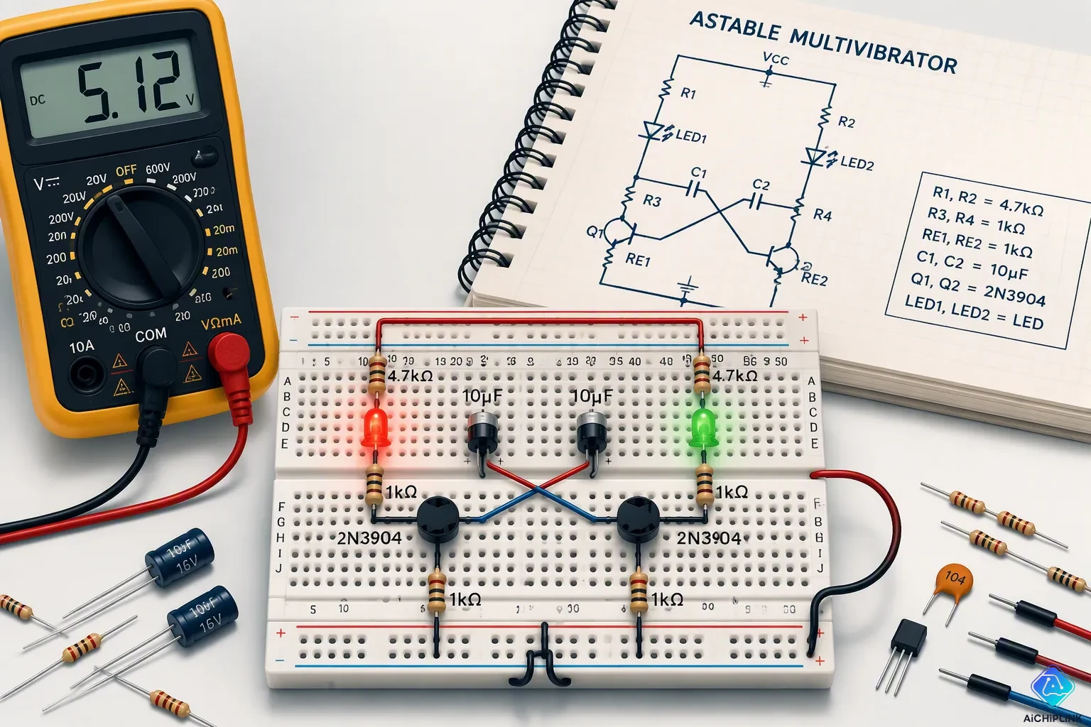
A multivibrator is a circuit that makes square waves by switching between two states. How do digital clocks keep time? They depend on this simple but strong building block. The circuit comes in three types. The astable multivibrator oscillates nonstop, the monostable makes a single pulse when triggered, and the bistable holds its state like a memory cell. Each type has a special role in electronics. The global astable multivibrator market was worth USD 479.3 million in 2024 and is expected to reach USD 651.1 million by 2030. More than one billion 555 timer units are made each year, showing how widely it is used. This application matters because it powers everything from timers to digital memory.
Key Takeaways
-
A multivibrator makes square waves. It flips between two voltage levels. This helps digital devices keep time.
-
There are three types. Astable keeps switching on and off without stopping. Monostable gives one pulse when you trigger it. Bistable holds its state, just like memory.
-
You can make a multivibrator with a 555 timer, an op-amp, or logic gates. These circuits make timing signals and pulses.
-
Multivibrators power many devices. They work in timers, memory, and alarm circuits. They clean signals and control motors.
What is a Multivibrator?
Basic Definition and Square Wave Output
This circuit makes square waves by flipping between two voltage levels. You can see it as a square wave maker. It builds a clean on-off pattern for digital devices. Square waves power clock signals and timing.
This circuit design makes a square wave output with slightly rounded edges. Capacitor charging creates this effect. Adding a transistor gives a nearly perfect square output. The output signal is a steady square wave from either collector. The amplitude is close to the supply voltage. The waveform can be symmetrical. A 1:1 mark-to-space ratio means equal on and off times. You can also make it non-symmetrical. RC timing parts control this balance.
A typical square wave maker creates a voltage swing from ground to the supply voltage. A logic gate astable swings between VDD and ground. You can figure out the frequency with a simple formula. For a symmetrical design, period equals T = 1.386 RC. Frequency equals one divided by the period. This gives a 50 percent duty cycle. For example, a 680 kΩ resistor with a 0.001 μF capacitor gives about 1.06 kHz.
Two Common States: Stable and Transient
This circuit depends on two types of states. A stable state is a long-term steady condition. It stays there without any trigger. A transient state is a short-term condition. The circuit enters this state when triggered. It cannot stay there forever. It returns to the stable state on its own.
| Type | Stable States | Trigger Requirement | Output Behavior | Application |
|---|---|---|---|---|
| Astable | None (unstable) | No outside trigger needed | Steady oscillation (square wave) | Clock maker, timing signal |
| Monostable | One stable, one temporary | Outside trigger pulse | Single pulse of set length (set by RC) | Debouncing, time delays, pulse stretch |
| Bistable | Two stable states | Outside trigger (Set/Reset) | Stays in state until next trigger (memory) | Memory parts, flip-flops, counters |
Each type uses these states in its own way. An astable multivibrator has no stable states. It keeps oscillating. A monostable multivibrator has one stable state. When triggered, it goes into a transient state. It comes back after a set time. A bistable multivibrator has two stable states. It remembers its last state until you change it. Each design has a special job in making signals and timing.
Multivibrator Circuit Configurations
You can build a multivibrator circuit in a few different ways. Each method has its own benefits. The most common setups use an op-amp, a 555 timer IC, or logic gate circuits.
Op‑Amp Based Multivibrator
An op-amp setup uses positive feedback and hysteresis to make steady oscillation. You send the feedback signal to the non-inverting input. This makes the circuit regenerative. The output quickly drives to one supply rail. The positive feedback network uses two resistors as a voltage divider. This sets a feedback fraction. It creates two separate threshold voltages. This is hysteresis. Hysteresis stops unwanted oscillations. Enough hysteresis ensures clean state changes. This creates a dependable switching action.
You pair this hysteresis with an RC feedback network. Place it between the output and the inverting input. The capacitor charges and discharges through the resistor. This makes a time-varying signal at the inverting input. The op-amp only changes states when the capacitor voltage crosses a threshold. The cycle repeats. This produces a steady square wave oscillation. The frequency depends on the RC time constant and the feedback fraction. For a 1 kHz design, use R1 = 35 kΩ, R2 = 30 kΩ, R = 50 kΩ, and C = 0.01 µF. When the feedback fraction β equals 0.462, the frequency simplifies to f = 1/(2RC).
555 Timer and Gate‑Based Circuits
The 555 timer IC gives you a popular way to build these designs. You set it in astable, monostable, or bistable mode. In astable mode, it works as a square wave generator for timing generation. The 555 timer handles timing and pulse generation. You can count on precise timing for your projects. It works as a dependable timing circuit.
For gate-based designs, the 4069 IC works well. This is a CMOS hex inverter. In an astable setup, the 4069 uses RC feedback to make a clean output wave. The circuit gives a sharp pulse. You get frequencies like 10 kHz with 10 V peak-to-peak. This approach is simple. You find it in embedded systems and educational labs. It works well for quick prototyping. The integrated gate multivibrator gives a simple oscillator for digital systems. You can also use NAND or NOR gates to build any of these configuration types. The integrated gate multivibrator approach gives you flexibility.
Astable Multivibrator
Working Principle and Continuous Oscillation
An astable multivibrator does not have a stable state. It flips between two states endlessly and works as a free-running oscillator. A discrete transistor version needs only a few parts.
| Component | Quantity |
|---|---|
| Transistors (Q1, Q2) | 2 |
| Capacitors (C1, C2) | 2 |
| Resistors (R1–R4) | 4 |
| DC power supply | 1 |

Capacitor C1 links the collector of transistor Q1 to the base of Q2. Capacitor C2 links the collector of Q2 to the base of Q1. This cross-coupling makes regenerative feedback. Each transistor turns the other on and off in turn. Collector resistors limit current through the transistors and any load, such as LEDs. Base resistors set how fast the capacitors charge, which sets the oscillation frequency and duty cycle.
You can predict the frequency of a symmetrical design. One transistor changes state in about 0.693 × R × C. The full period is twice that value, or about 1.386 × R × C. The standard formula is f = 0.72 / (R × C), where R is the base resistance and C is the capacitance. With R = 47 kΩ and C = 10 µF, the frequency is 0.72 / (47,000 × 0.000010) = 1.5 Hz.
Output Waveform and Duty Cycle Control
A basic astable multivibrator makes a square wave with a fixed duty cycle. You often need to change that balance. A 555 timer in astable mode gives you several ways to adjust it.
One method puts a diode in parallel with R2. The diode shorts out R2 while the capacitor charges, so the capacitor charges only through R1. The duty cycle becomes R1/(R1 + R2), and you can push it below 50 percent by making R1 smaller than R2. A second diode in series with R2 separates the charge and discharge paths completely. The charging time becomes 0.693 × R1 × C, and the discharging time becomes 0.693 × R2 × C.
A variable resistor gives you continuous control. In one setup, a 100 KΩ potentiometer splits into RVU and RVL. The capacitor charges through R1, D2, and RVU, so T_ON = 0.693 × (R1 + RVU) × C1. It discharges through RVL, D1, R2, and pin 7, so T_OFF = 0.693 × (RVL + R2) × C1. This keeps the frequency fixed while the pulse width changes. Without diodes, the standard 555 astable only reaches duty cycles between 50 and 100 percent.
Monostable Multivibrator
Triggering Mechanism and One‑Shot Operation
A monostable multivibrator has one stable state. It stays there until a trigger comes in. Then the circuit switches to a temporary state for a set time. After that, it goes back to the stable state by itself. This setup makes it a one-shot pulse generator.
A transistor-based design uses two transistors and several passive parts. Timing resistor RT connects from Vcc to the base of transistor TR2. Timing capacitor CT connects between the collector of TR1 and the base of TR2. Together they set the output pulse width. Trigger capacitor C1 couples an external negative pulse to the base of TR1. A blocking diode stops reverse current. The output wave is a single clean pulse each time you trigger the circuit.
In the stable state, TR2 stays ON and saturated. TR1 stays OFF. A negative trigger pulse turns TR1 ON. Its collector voltage drops. This pulls the base of TR2 low through capacitor CT. TR2 turns OFF. Its collector goes HIGH. This marks the start of the unstable state.
For a 555 timer monostable, the trigger mechanism works this way:
A timing interval starts when the trigger input is brought low. When this happens, the 555 output goes high. This causes the capacitor to be charged until it reaches 3.3V. Then, the timing interval ends, the output goes low, and the capacitor is discharged through the "dis" input.
A capacitor in front of the trigger input makes the circuit negative-edge triggered. If you replace that capacitor with a wire and hold the input low too long, the output will start to oscillate.
Pulse Width Determination and Reset
The output wave shape depends on the RC time constant. The pulse width equals T = 0.693 times R times C for a general monostable circuit. R stands for resistance in ohms. C stands for capacitance in farads. For a 555 timer, the formula becomes TW = roughly 1.1 times R times C. A transistor-based monostable uses the formula Pulse Period = negative 0.7 times R2 times C1.
You can adjust the pulse width. Add a 1M trimmer potentiometer in series with the timing resistor. This makes the pulse width adjustable between 0.5 and 300 milliseconds.
The monostable acts as a non-retriggerable device. It ignores extra triggers until the timing capacitor fully discharges. If you trigger the circuit too early, the output pulse may become shorter than you wanted. The input connects to an open-collector source because TR1 shorts the input to ground during the active output state.
This circuit works for signal conditioning and debouncing. It turns a noisy signal into a clean pulse. It also gives precise timing delays. These circuits form building blocks for pulse width modulation systems.
Bistable Multivibrator
Latching Behavior and Memory Function
A bistable multivibrator has two steady output states. It stays in either state forever until an outside trigger makes it change. You can think of it as a one-bit memory cell. The circuit keeps its last value without any power-hungry refresh cycle.
Bistable circuits have two steady output states and stay in either state forever until an outside input triggers a switch. They use positive feedback or latching transistor setups to hold one of two clear output voltages that match logic 1 and logic 0. In transistor form, a cross-coupled pair keeps one device in saturation while the other is cut off; the regenerative feedback makes either state self-sustaining.
You build this latching action with two cross-coupled inverting stages. In a discrete design, each stage uses a bipolar junction transistor. A single common-emitter stage flips its input. Two such stages in a loop create a non-inverting path. Each transistor feeds the other. This regenerative loop locks the output in place. The multivibrator then stores that binary value until the next trigger arrives.
Set‑Reset Operations and Flip‑Flop Basics
You control the state with two inputs: Set and Reset. A pulse on the Set input forces the output high. A pulse on the Reset input forces it low. The circuit ignores both inputs when neither is active. This simple rule makes the bistable multivibrator a basic flip-flop.
The cross-coupled pair forms the heart of this memory element. Each transistor's collector drives the other's base. This positive feedback keeps one device conducting while the other stays off. The output signal sits at a clear logic level. A trigger pulse disturbs the balance. The devices switch roles. The circuit then settles in the opposite state. You can cascade these flip-flops to build counters and shift registers. The output wave from each stage feeds the next stage's clock input. This division of frequency turns a fast signal into a slower one. The same principle powers digital memory and sequential logic across countless electronic systems.
Multivibrator Applications
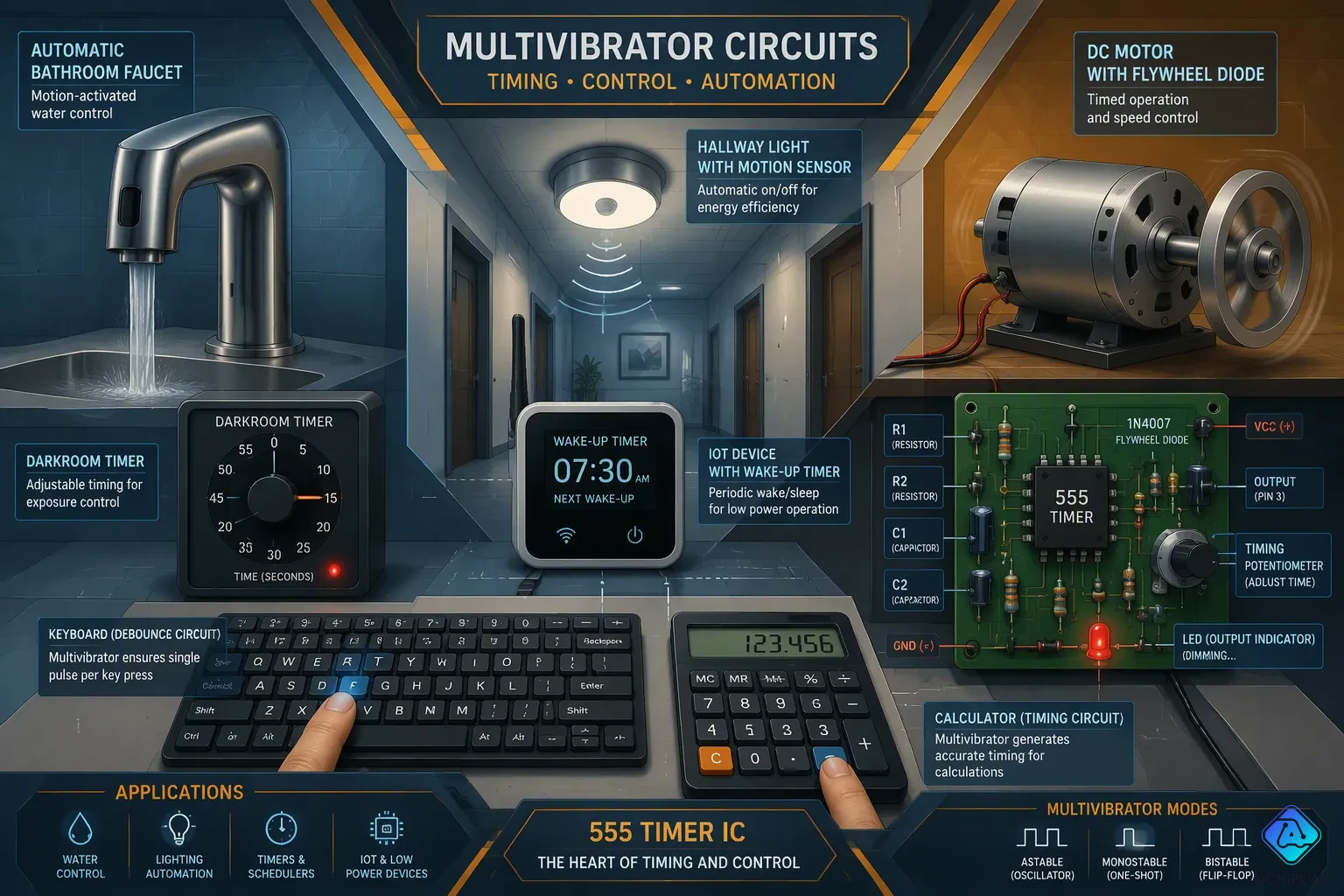
Timing, Pulse, and PWM Applications
You can find multivibrator circuits in many things you use every day. A monostable multivibrator cleans up switch signals in computer keyboards, calculator buttons, and elevator buttons. Automatic bathroom faucets use a hand trigger to start water for a set 5-second cycle. Darkroom timers turn on a safety light for a set time after you press a button. Hallway lights that save energy stay on for 2 minutes before they turn off by themselves. Industrial sensors use these circuits to filter noise and shape pulses. IoT devices use wake-up timers like the TLC555 to turn systems on only during set time windows. This cuts down power use in battery-powered devices.
| Product | Timing Function |
|---|---|
| Computer keyboards | Switch debouncing |
| Automatic lavatory faucets | 5-second timed water flow |
| Darkroom timers | Preset safety light duration |
| Energy-saving hallway lights | 2-minute automatic turn-off |
| IoT devices | Wake-up timing windows |
You can make pulse width modulation with an astable multivibrator to control motors. The PWM 555 circuit uses R1 and C1 to set the frequency. A 10 kΩ potentiometer (RV1) changes the duty cycle. Changing the duty cycle changes the average voltage at the output. This lets you control the speed of a DC motor or dim an LED. The output at pin 3 switches the motor drive transistor fully ON and fully OFF. Power loss in the switching device stays low. A higher duty cycle sends a larger average DC voltage to the motor, which makes it faster. A lower duty cycle lowers the average voltage and slows the motor down. The astable frequency should be at least a few hundred hertz so the motor does not jerk. A flywheel diode protects the circuit from the motor's inductive load.
Memory, Frequency Division, and Alarm Circuits
A bistable multivibrator changes state only when an outside trigger pulse comes in. It takes two trigger pulses for the circuit to finish one full cycle. The output waveform finishes one cycle for every two input pulses. The output frequency is exactly half of the input frequency. This divide-by-two action makes the bistable multivibrator helpful in digital counting jobs. You can link these stages together to build counters and shift registers.
A temperature-controlled alarm shows a real use. An astable multivibrator works as a clock generator. A monostable multivibrator makes a triggered alarm pulse when the temperature goes past a set level. The monostable also handles delayed activation and deactivation. A sensor detects an object, and the rising edge of the output pulse turns on a device after a delay of T. For delayed deactivation, the device keeps working for T time after the event before it stops. Pulse shaping and debouncing turn a noisy switch signal into a clean, fixed-width rectangular pulse. This gives digital circuits a single clear logic signal. These timing circuits give reliable generation and timing accuracy for industrial and consumer systems.
An astable multivibrator has no stable state and keeps oscillating on its own. A monostable multivibrator holds one stable state and makes a single pulse when triggered. A bistable multivibrator keeps two stable states and remembers its last value.
You will find this circuit in many places, from simple LED flashers to digital memory. Get a 555 timer or a few discrete transistors and build one yourself. Watch the output wave change as you adjust the timing parts. That signal teaches you more than any textbook.
Learn these three types well, and you build a foundation for counters, oscillators, and advanced application designs.

Written by Jack Elliott from AIChipLink.
AIChipLink, one of the fastest-growing global independent electronic components distributors in the world, offers millions of products from thousands of manufacturers, and many of our in-stock parts is available to ship same day.
We mainly source and distribute integrated circuit (IC) products of brands such as Broadcom, Microchip, Texas Instruments, Infineon, NXP, Analog Devices, Qualcomm, Intel, etc., which are widely used in communication & network, telecom, industrial control, new energy and automotive electronics.
Empowered by AI, Linked to the Future. Get started on AIChipLink and submit your RFQ online today!
Frequently Asked Questions
What is the difference between astable, monostable, and bistable multivibrators?
An astable multivibrator has no stable state and keeps oscillating nonstop. A monostable multivibrator has one stable state and makes a single pulse when triggered. A bistable multivibrator has two stable states and holds its last value like a memory cell.
How do I calculate the frequency of an astable multivibrator?
For a symmetrical design, use the formula f = 0.72 / (R × C). R is the base resistance in ohms. C is the capacitance in farads. With R = 47 kΩ and C = 10 µF, the frequency is about 1.5 Hz.
What sets the pulse width in a monostable multivibrator?
The RC time constant controls the pulse width. For a general monostable, the pulse width equals 0.693 × R × C. A 555 timer uses roughly 1.1 × R × C. You can add a trimmer potentiometer to adjust the timing.
How does a bistable multivibrator store memory?
Two cross-coupled inverting stages create a regenerative loop. Each transistor feeds the other. This positive feedback locks the output in place. A Set pulse forces the output high. A Reset pulse forces it low. The circuit ignores both inputs when neither is active.
Can I build a multivibrator without a 555 timer?
Yes. You can use an op-amp with positive feedback and an RC network. You can also use logic gates like the 4069 CMOS hex inverter. A discrete transistor design needs only two transistors, two capacitors, and four resistors. Each circuit works well for different needs.