When it comes to controlling the starting mechanism of three-phase motors, the Star-Delta (Y-Δ) starting method is one of the most common and efficient ways to reduce the initial current surge. The Automatic Star-Delta Starter using a timer simplifies this process by incorporating an automatic transition between the star and delta connections, making it more reliable and safer in industrial applications.
In this blog, we’ll dive into how an automatic Star-Delta starter operates using a timer, the importance of its power and control wiring, and explore the wiring diagrams to ensure the proper setup for your system.
What is a Star-Delta Starter?
A Star-Delta starter is a motor starting method primarily used for reducing the high starting current of three-phase motors. When starting a motor directly across the line, the inrush current can be as high as 6 to 8 times the full-load current. The Star-Delta method helps reduce this inrush current by initially connecting the motor windings in a star configuration, which reduces the voltage across each winding to 58% of the line voltage. Once the motor reaches a certain speed, the connection is switched to a delta configuration, which allows the motor to operate at full voltage.
Why Use an Automatic Star-Delta Starter?
An automatic Star-Delta starter offers several advantages over the manual version. While manual starters require an operator to switch between the star and delta configurations, the automatic version uses a timer or electronic control system to perform this transition automatically. This removes the need for human intervention and ensures that the motor starts safely and efficiently. Additionally, automatic starters can reduce maintenance costs and the potential for human error, leading to more reliable operation.
Key Components of the Automatic Star-Delta Starter
An Automatic Star-Delta starter system consists of several key components:
1. Contactor (K1, K2, K3) – These are electromagnetic switches used to make or break the motor windings' connection in the star and delta configurations.
2. Timer (T1) – The timer controls the duration for which the motor runs in the star configuration before switching to the delta configuration.
3. Overload Relay (OLR) – This safety feature prevents the motor from running under overload conditions, thus protecting the motor and starter.
4. Motor (M) – The three-phase induction motor that is started using the Star-Delta method.
5. Auxiliary Contactors – These contactors ensure that the star and delta configurations don’t overlap, avoiding short circuits during the transition.
How Does the Automatic Star-Delta Starter Work?
The automatic Star-Delta starter works as follows:
• Motor Starting in Star Configuration – When the motor is energized, the timer initially connects the motor windings in the star configuration (Y). This reduces the applied voltage across the motor windings and consequently reduces the starting current.
• Time Delay via Timer – The timer begins its countdown after the initial start-up. The delay is usually set based on the motor’s load and the time required for it to accelerate to a certain speed. This delay typically ranges from 2 to 10 seconds, but it may vary depending on the motor’s specifications.
• Switch to Delta Configuration – Once the timer reaches the pre-set delay, it sends a signal to change the contactor positions, shifting the motor windings from the star (Y) configuration to the delta (Δ) configuration. In the delta configuration, the motor receives full line voltage and operates at its rated power.
• Motor Continues Running in Delta Configuration – After the transition, the motor continues to run at full speed, with the starting current now reduced, and the motor operates at its rated torque and efficiency.
• Overload Protection – If there is any overload condition during the operation, the overload relay will disconnect the motor from the power supply, preventing damage.
Wiring, Power & Control Diagrams of Star Delta Starter
Power Diagram
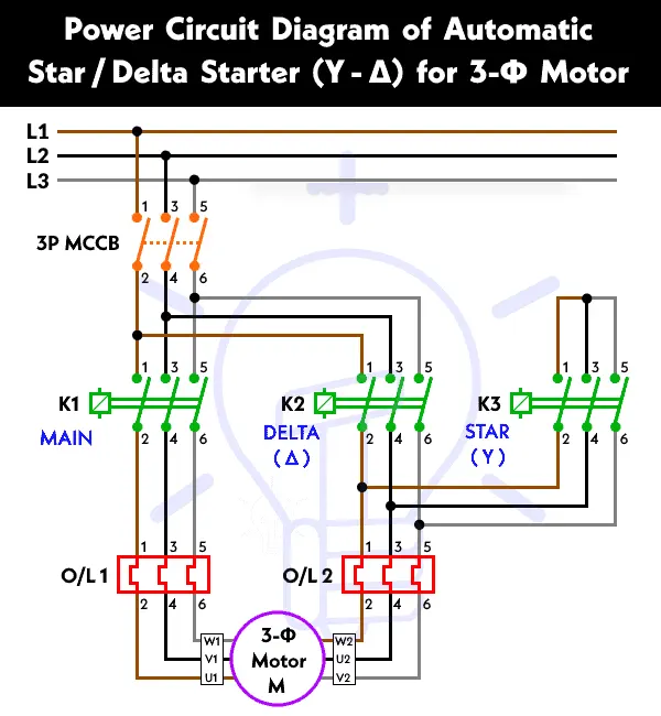
Power Circuit Diagram of Star Delta Starter
Schematic Wiring Diagram
Control Diagram
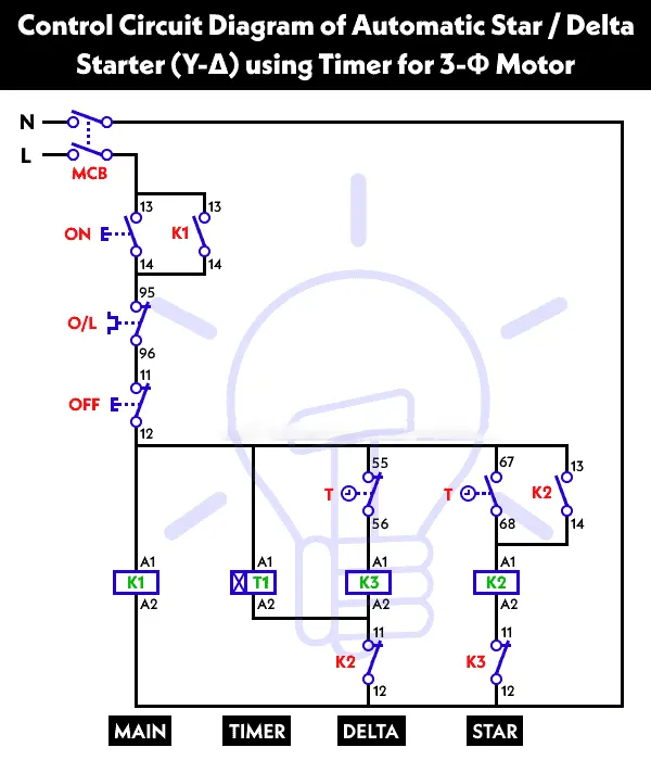
Control Diagram of Star Delta Starter using Timer
Control Circuit Diagram of Star Delta Starter with Timer
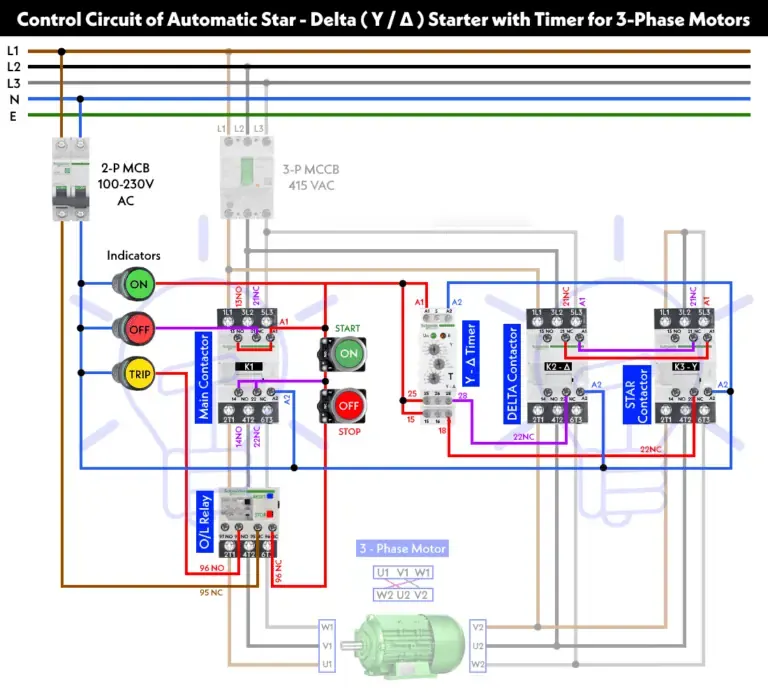
Automatic Star-Delta (Y-Δ) Starter with Timer for 3-Phase Induction Motor
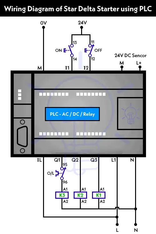
Wiring Diagram of Y-Δ Starter using PLC
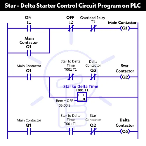
Ladder Diagram of Y-Δ Starter using PLC
Control and Power Wiring Diagrams for Automatic Star-Delta Starter
Now that we understand how the system works, let’s dive into the power and control wiring diagrams necessary to connect an automatic Star-Delta starter.
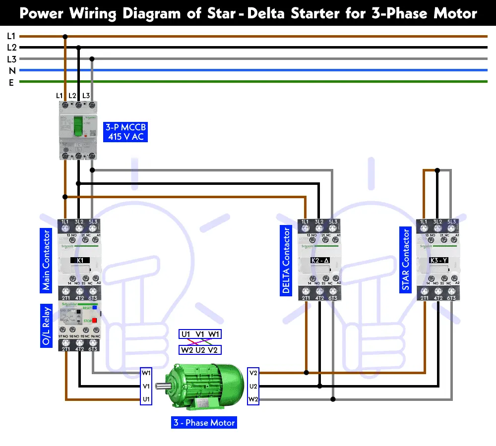
Power Wiring Diagram:
The power wiring diagram involves the connection of the three-phase supply to the motor via contactors and overload relays. Here’s a simple step-by-step process:
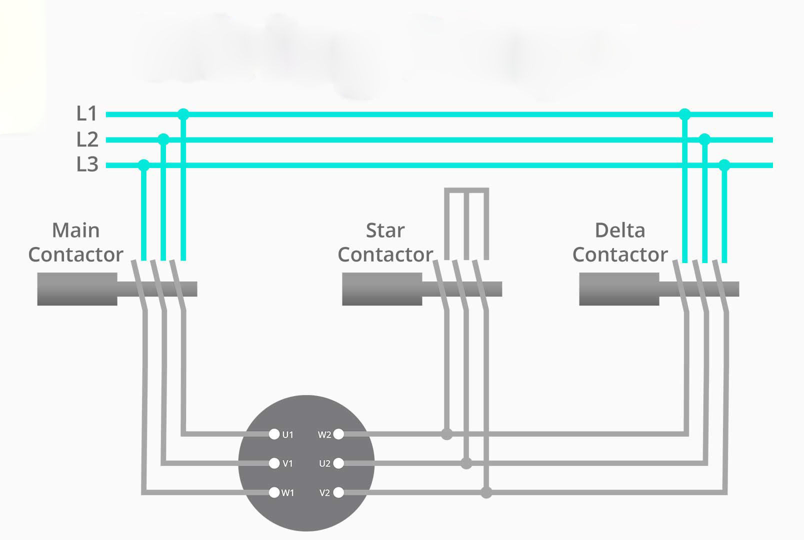
1. Connect the three-phase supply (L1, L2, L3) to the input terminals of the contactor K1.
2. The motor is connected to K1, with one set of the windings (U, V, W) connected to the terminals of K2 and the other set of windings connected to K3.
3. When the K1 contactor is closed, the motor is in the star configuration (Y), with the winding terminals U, V, W connected in the star pattern.
4. Upon timer completion, K2 and K3 engage, switching the motor into delta configuration, with the windings connected as per the delta (Δ) pattern.
Control Wiring Diagram:
The control wiring diagram governs the operation of the contactors and the timer. Here’s a typical setup:
1. The start button (S1) connects the control circuit to energize the contactor K1.
2. The timer (T1) is wired in series with K1, with its output controlling the operation of K2 and K3.
3. K2 and K3 have auxiliary contacts that prevent both contactors from engaging at the same time, ensuring the transition from star to delta is smooth and without short circuits.
4. An overload relay (OLR) is wired into the control circuit to provide protection to the motor.
Wiring Diagram for the Motor Starter:
Here’s a general overview of the wiring components and their layout:
• Power Supply (L1, L2, L3) feeds into the starter system.
• Contactor K1 is connected to the supply, with one set of the motor windings (U, V, W) wired in a star pattern.
• Timer T1 is connected in series with K1 and controls the delay before transitioning to delta.
• Contactor K2 and K3 are responsible for shifting the windings to the delta configuration after the timer completes the delay.
• Overload Relay OLR is connected to the control circuit to disconnect the motor in case of overload.
Basic Control Circuit:
Basic Power Circuit:
Advantages of Using Automatic Star-Delta Starter
1. Reduced Starting Current – The primary benefit is that it significantly reduces the inrush current, preventing damage to the motor and electrical components.
2. Automatic Operation – The automated transition between star and delta reduces human error, leading to more reliable motor operation.
3. Energy Efficiency – By limiting the starting current, the automatic Star-Delta starter optimizes energy consumption during motor startup.
4. Motor Protection – The overload relay protects the motor from overcurrent conditions, extending its lifespan.
Conclusion
The Automatic Star-Delta Starter is an essential device in modern industrial motor control. By using a timer to manage the transition from star to delta configurations, it ensures smooth motor starts with reduced inrush current, preventing equipment damage and optimizing energy use. Whether you're setting up a new motor or retrofitting an existing one, understanding the power and control wiring diagrams is critical to ensuring proper operation and safety.
If you’re looking to implement or troubleshoot an automatic Star-Delta starter system, always refer to the manufacturer’s manual for specific wiring instructions and safety recommendations.
Written by Icey Ye from AIChipLink.
AIChipLink, one of the fastest-growing global independent electronic component distributors in the world, offers millions of products from thousands of manufacturers. Whether you need assistance finding the right part or electronic components manufacturers for your design, you can contact us via phone, chat or e-mail. Our support team will answer your inquiries within 24 hours.