PWM vs DAC: Which Delivers Superior Analog Output Quality?
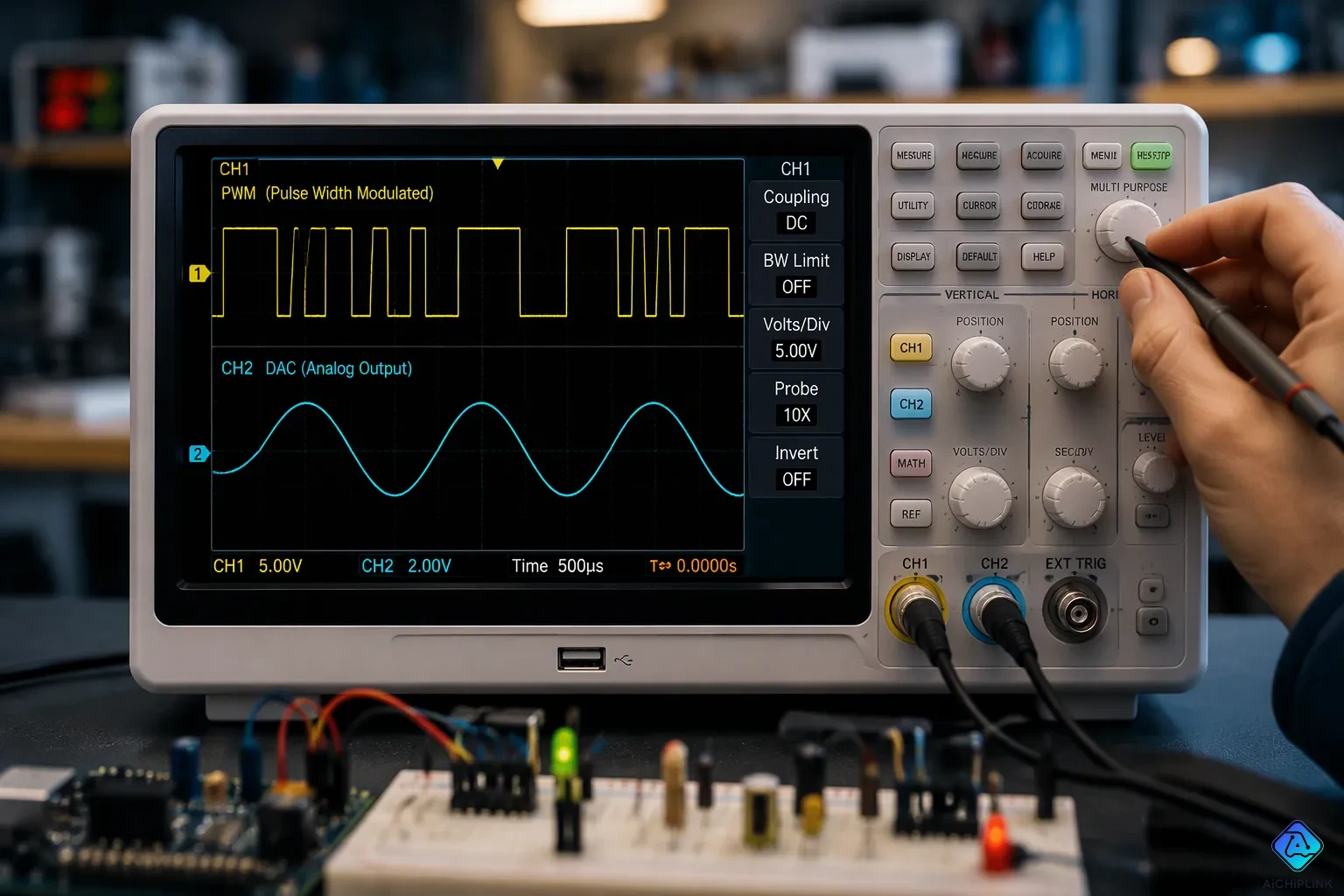
A dedicated DAC usually gives better analog output quality. It has lower noise, higher accuracy, and better linearity. A PWM output can still work well for less demanding designs. The choice is a trade-off between quality and cost, complexity, and what the application needs. A filtered PWM channel is cheap and simple, but it has ripple and digital noise. A DAC output costs more and needs careful layout, but it gives stable, precise results. This comparison looks at both technologies using concrete metrics to answer the question: Which Provides Better Analog Output Quality? A practical decision guide then helps you match the right option to your design. The real question is not which gives better analog output quality in theory, but which fits your requirements.
Key Takeaways
-
A DAC gives cleaner analog output with less noise and higher accuracy.
-
PWM costs less and is easier to use, but it needs filtering to lower ripple.
-
Use a DAC for tasks that need high accuracy, like audio and instrumentation.
-
Pick PWM for jobs where cost matters, like motor control and LED dimming.
-
Pick the technology that fits what you need by looking at resolution, noise, and cost.
PWM vs DAC Output: The Basics
What a DAC Does
A digital-to-analog converter changes a number into a voltage. It adds up weighted values inside the chip. Each input bit adds a scaled part of the reference, so the output rises with the digital code. The result is a true analog voltage that follows the input smoothly.
Bit depth sets the resolution. More bits mean finer steps and a more exact output. This is why dacs are used in high-fidelity audio and instrumentation, where precision and linearity matter. A dac also handles hard tasks that a simple timer cannot. The dac output stays steady between updates, with no switching edges of its own.
How PWM Approximates Analog
Pulse width modulation takes a different path. It flips a digital pin very fast and changes the duty cycle. The average of that square wave copies the target level. A 3.3 V signal gives about 0.825 V at 25 percent, 1.65 V at 50 percent, and 2.475 V at 75 percent.
This method is easy to set up and wastes less power. That makes pwm a natural fit for motor control and LED dimming. It is also the usual way to make analog voltages with microcontrollers, since most chips already include a pwm timer. The trade-off is clear: pwm and dac output differ in nature, not just in quality. One gives a real analog voltage output; the other gives pulses whose average stands in for it. Understanding pwm vs dac output starts with that difference.
Analog Output: Core Differences
Continuous vs Switched Output
A dac holds its output steady between updates. The voltage sits at one level and changes only when a new code arrives. This gives smooth, continuous signals with no switching edges of their own. The output is a real analog voltage that follows the digital input. A scope shows a flat line that steps to a new level and stays there.
Pulse width modulation works by switching. The pin flips between high and low at a fixed frequency, and the duty cycle sets the average. That average is the analog voltage the circuit sees after filtering. The waveform itself is a square wave, not a steady level. This is the first core difference between pwm and dac output: one is continuous, the other is switched. The switched nature also means the load sees the full supply swing on every cycle.
Resolution and Quantization
Resolution sets how finely the output can step. A dac with more bit depth divides the full range into smaller steps. An 8-bit output gives 256 levels across the range. A 12-bit dac gives 4096 levels, so each step is much smaller. The step size equals the full range divided by the number of levels. The quantization error shrinks as resolution rises. Each extra bit halves the step size.
Typical pwm timers offer about 8 bits of resolution. That is enough for LED dimming and motor speed, but coarse for precision work. Many dacs offer dual and quad channels with higher resolution than 8 bits, accessed through fast I2C or SPI interfaces. Digital-to-analog converters also keep their dac output stable between codes, so the analog output stays clean. A pwm channel needs filtering to reach a similar result, and the filter adds delay. A dac settles to a new level quickly and holds it. For fine steps and multiple channels, the dac is the stronger fit.
Noise and Ripple Performance
DAC Noise Characteristics
Noise sets the lowest limit for any precise analog voltage. A dac makes very little of it. The output noise density of a good dac stays far below the level that would bother a sensitive load. One dac used in an ion-trap control system reached 78 μV/√Hz over the 0.1–10 Hz band, which met an ultra-low noise requirement. The TI DAC11001A goes even further. This 20-bit dac lists 49 nV/√Hz and settles in about 1 μs.
| DAC Device | Output Noise Density | Notes |
|---|---|---|
| Unspecified DAC (ion-trap control) | 78 μV/√Hz | 0.1–10 Hz band; meets ultra-low noise requirement |
| TI DAC11001A | 49 nV/√Hz | 20-bit resolution; ~1 μs settling time |
These numbers show why dacs fit instrumentation and audio. The dac output stays quiet between updates. No switching edges disturb the real analog voltage. Layout still matters, and a noisy reference will make any dac worse.
PWM Ripple and Switching Artifacts
A pwm output carries artifacts that a dac does not. The most obvious is ripple from pwm at the switching frequency and its harmonics. This leftover AC voltage follows the switching operation directly. Low-frequency broadband noise also shows up, caused by reference noise, and it can create phase noise in sensitive RF and PLL circuits. High-frequency ringing near 100 MHz and above comes from fast switching transitions and parasitic inductance in the input loop. That ringing leads to EMI and signal-integrity problems.
The duty-cycle range adds another limit. Rise and fall times of 5–50 ns cut into the usable range at high frequency. At 1 MHz, 20 ns transitions lose about 4 percent of the range. Near 0 or 100 percent duty, dead zones make the output unpredictable. Filtering helps, but pwm signals always need that extra stage. A dac avoids the problem at the source.
Linearity and Accuracy of DACs
Linearity is about how closely the output steps follow a straight line over the whole range. Accuracy is about how close the real analog voltage gets to the ideal value. These two ideas are related, but they are not the same thing. A converter can be very linear and still miss the target level by a fixed amount.
INL, DNL, and Monotonicity
Integral nonlinearity (INL) measures the biggest gap between the transfer curve and a straight line. Differential nonlinearity (DNL) measures how far each step size drifts from the ideal one-step value. Monotonicity means the output always goes up when the input code goes up, and never drops back. A dac with good DNL stays monotonic, which matters in control loops and audio. Poor DNL can cause missing codes or flat spots. Designers often check these specs on a bench sweep, stepping through every code and recording the output.
Dacs usually win on precision. Their internal resistor networks and trimmed references give tight INL and DNL, and high resolution and linearity go together in well-designed parts. But a dac is not automatically perfect. Its accuracy depends on the reference or supply voltage. A noisy or drifting reference shifts the whole transfer curve, so the dac output picks up that error. The converter is only as good as the voltage it scales. Bit depth sets the step size, but the reference sets the true span. So a precision voltage reference matters as much as the converter itself.
PWM Linearity Limits
A pwm-based converter acts differently. Its linearity is often very good, because the duty cycle maps to the average value in a nearly straight line. Absolute accuracy is the weaker point. The average depends on the supply rail, the switch behavior, and the filter, so the final analog voltage drifts more than a standalone dac would. The switched waveform averages out in the filter, and that averaging is quite even across the range.
Several effects wear down performance. Unequal rise and fall edge times add offset and linear error, since the edges are never the same length. A changing number of switching edges per counter period also hurts the result; keeping the edge count low, around 100 Hz, and using symmetrical switches helps. Switch on-resistance changes with temperature and voltage, and that non-linear change corrupts the transfer function. Leakage current through switches adds error current; a simple reference-switch-filter chain tops out around 15-bit and 10 ppm. Charge injection causes offset, which switching on the reference side and a dual switch can reduce. Reference buffer settling under dynamic load and analog filter settling time both limit usable accuracy at speed.
| Limitation | Effect on Output |
|---|---|
| Unequal rise/fall edges | Offset and linear error |
| Variable edge count per period | Degrades accuracy; keep edges low, switches symmetrical |
| Switch on-resistance variation | Non-linear transfer function |
| Leakage current | Error current; simple topology near 15-bit / 10 ppm |
| Charge injection | Offset; mitigate with reference-side and dual switching |
| Reference buffer settling | Limits accuracy under dynamic load |
| Filter settling time | Limits update rate and effective accuracy |
The takeaway is balanced. A dac gives stronger precision and a cleaner real analog voltage. Dacs also keep their output steady between codes. A pwm channel can be quite linear, but its absolute accuracy falls behind a dedicated part. Match the part to the accuracy your measurement or control loop truly needs.
Settling Time and Dynamic Response
DAC Settling Behavior
Settling time tells you how fast the output reaches its final value and stays there. A dac moves to a new level in one small step. The output then holds that level until the next code arrives. Fast settling matters in waveform generation, control loops, and multiplexed systems. A slow converter smears fast signals and limits the update rate.
Settling time depends on the size of the step. Small steps settle quickly. Large steps take longer, because the internal amplifier needs more time to swing across the range. The table below shows two examples from real parts.
| DAC Part | Settling Time | Condition |
|---|---|---|
| DAC60004 | 8 µs (max) | — |
| DAC9881 | 5 µs | Large-signal step from code 0x04000 to 0x3C000 (near full-scale) |
The DAC9881 reaches its final value in 5 µs even on a near full-scale step. The DAC60004 guarantees 8 µs or better across all units. These speeds suit most control and instrumentation tasks. A dac output also stays flat between updates, so the analog voltage does not drift on its own.
PWM Update Rate and Filter Delay
A pwm channel faces a different limit. The raw square wave is not usable as a clean analog voltage. It needs a filter to smooth the pulses into a steady level. That filter adds delay, and the delay grows as the filter gets stronger. A heavy filter kills ripple but slows the response. A light filter responds fast but leaves ripple behind.
The update rate also depends on the pwm frequency and the counter resolution. Higher resolution means more counts per period, so each update takes longer. Designers often trade resolution for speed. The filter then adds its own settling time on top. A pwm stage can respond quickly in simple dimming tasks. Precision work with tight ripple limits pays a real penalty in speed. Dacs avoid this trade-off, since the output needs no filter to become a real analog voltage.
Filtering PWM for Cleaner Output
RC Filter Sizing and Ripple Suppression
A raw pulse train cannot serve as a steady level. Turning pwm into an analog voltage requires a low-pass stage that averages the pulses. The filter size determines how much ripple is left. For a single-stage RC low-pass filter, the worst-case peak-to-peak ripple at 50 percent duty cycle is about Tpwm divided by 4RC, where Tpwm is the pwm period. A longer time constant reduces ripple in a predictable way.
That trade-off comes at a cost. To reach 8-bit resolution, where ripple equals 1 LSB or Vs/256, you need an RC time constant near 64·Tpwm. Settling then stretches to about 355·Tpwm, which is roughly 35 ms at 10 kHz. A 10-bit target pushes settling to about 177 ms at the same rate. A ripple-cancellation scheme that injects an inverted pwm signal cuts the required constant from 64·Tpwm to 4·Tpwm and settles in about 4.4 ms at 10 kHz.
| Configuration | Ripple target | Required RC time constant | Settling time |
|---|---|---|---|
| Single-stage RC (8-bit) | 1 LSB (Vs/256) | 64·Tpwm | 355·Tpwm (~35 ms at 10 kHz) |
| Single-stage RC (10-bit) | 1 LSB | larger | ~177 ms at 10 kHz |
| Ripple-cancellation (8-bit) | 1 LSB | 4·Tpwm | 44·Tpwm (~4.4 ms at 10 kHz) |
| Ripple-cancellation (10-bit) | 1 LSB | — | ~11 ms at 10 kHz |
When Filtering Costs Outweigh Savings
A filtered pwm signal can get close to a dac output in accuracy, but the gap seldom closes fully. The dac usually wins on analog accuracy. The filter adds parts, board space, and delay. A two-stage RC chain reaches the same ripple with shorter time constants, for example 41·Tpwm settling against 16 ms for a single stage. That trades component count for speed, not for free performance.
A basic single-bit sigma-delta dac offers another route. It outputs a low-MHz binary sequence that represents an analog signal more accurately than a pwm signal does. For a smooth analog output with tight noise limits, dacs remain the simpler answer. A filtered pwm signal still fits cost-sensitive designs that need a clean analog control voltage and can accept the extra settling delay.
Cost and Application Fit
Where DACs Excel
A dac is a good choice for designs that need a clean, predictable signal. A programmable analog reference voltage is a good example. The dac gives a true, clean analog voltage instead of a filtered square wave. Analog setpoints for power supply voltage or current limit also work better with a dac. Ripple from a pwm can cause instability or measurement errors in the receiving circuit. Simulating sensor output for temperature, calibration, or ADC testing is another strong fit. The dac output is cleaner, more predictable, and easier to repeat than a filtered pwm signal.
| Application | Why the dac is superior |
|---|---|
| Programmable analog reference voltage | Gives a true, clean analog voltage instead of a filtered square wave |
| Analog setpoints (supply voltage, current limit) | pwm ripple can cause instability or measurement errors |
| Sensor output simulation (temperature, calibration, ADC testing) | Cleaner, more predictable, and easier to repeat output |
| Control voltage for analog circuits | Receiving circuits expect a real analog voltage |
| Multi-channel analog setpoints | External dacs such as the MCP4728 give several real outputs from one module |
Audio is the classic trade-off. A dac gives good sound quality and low distortion, but it costs more. That cost buys low noise and strong linearity, which demanding audio and instrumentation designs need.
Where PWM Is the Right Fit
A pwm channel fits cost-sensitive designs with modest demands. Motor speed control, LED dimming, and heater drive all work well with a switched output. These loads average the pulses on their own, so no filter is needed. A filtered pwm stage also suits slow control loops that can accept extra settling delay. The timer is already inside most microcontrollers, so the part count stays low.
The choice comes down to the job. Pick a dac when precision, low noise, and a steady analog voltage matter. Pick pwm when cost, simplicity, and board space lead the list. Neither option is wrong. Each one fits a different set of requirements.
Which Provides Better Analog Output Quality?
The answer to which provides better analog output quality? depends on six criteria: resolution, noise budget, accuracy, cost, board space, and update rate. No single rule settles the pwm and dac output debate. Each design weighs these factors in its own way, and the right balance shifts with the job. A careful reader can rank the two options for a given circuit in a few minutes.
Key Selection Criteria
| Criterion | DAC | PWM |
|---|---|---|
| Precision / resolution | Better; high resolution and linearity; smooth continuous output | Lower precision; built-in noise and ripple |
| Linearity | Good, works well for precise instrumentation | Affected by component non-linearities |
| Cost | Higher because of precision components | Lower and cost-effective |
| Complexity | More complex design (signal integrity, noise reduction) | Simpler; easy to integrate with microcontrollers |
| Power efficiency | Less emphasized | Prioritized; good for motor/LED drive |
| Best-fit applications | Audio processing, precise instrumentation | Budget projects, motors, LEDs, efficiency-focused designs |
Resolution sets the first limit. Higher resolution in a pwm stage forces a slower switching frequency. A slower frequency then needs higher-order low-pass filters to suppress ripple while keeping settling time reasonable. A passive first-order RC filter becomes impractical beyond roughly 10 bits of resolution, where long settling time fights too much ripple. Active filters help, but each op-amp adds drift and cost. At 20+ bits, expensive zero-drift amps with low gain-bandwidth are needed and still struggle to filter high-frequency components. Component non-linearities matter at high bit counts, and delta-sigma modulated dacs offer advantages over simple pulse-width converters. Each added bit halves the step size, so the filter must work harder as resolution climbs. A designer who needs 12 bits must accept a slower update or a larger filter. Neither choice is free.
A dac suits audio and instrumentation, where precision matters. A filtered pwm stage fits budget projects, motors, and LEDs. The dac output stays smooth and continuous between codes. The converter also holds a steady analog voltage with no switching edges. Cost favors the switched approach, and the precision part costs more. Board space and update rate decide the rest. Careful layout matters, and the converter settles fast without a filter. The switched route wins on simplicity and power efficiency, which suits motor and LED drive. A slow control loop tolerates the extra settling delay of a filter. A fast waveform generator does not. Neither option is wrong.
A Practical Checklist
Ask which provides better analog output quality? before choosing a part. The list below turns the criteria into plain questions. Skip a question only when the answer is obvious for your circuit. Work through them in order:
-
Does the load need fine steps? A dac gives finer resolution than a timer.
-
Is the noise budget tight? A dac keeps ripple low at the source.
-
Does accuracy depend on a stable reference? Check the reference before trusting any dac.
-
Can the board spare filter parts and delay? The filter stage costs both.
-
Does the update rate matter? A dac settles without filter delay.
-
Is cost the leading constraint? A switched channel is cheaper and simpler.
Answer these honestly, and which provides better analog output quality? becomes clear for your design. Match the part to the requirement, and the design stays honest. That habit beats defaulting to one technology.
For analog output quality, the dac is usually the better pick. It has lower noise, higher accuracy, and better linearity. A dac output also keeps a steady analog voltage between updates.
Each option still has a clear place. Pick a dac for precision work, low-noise designs, and dynamic applications. Pick pwm for cost-sensitive or lower-demand designs, especially when filtered pwm works for you.
Think about your own needs before you decide. Check resolution, noise budget, cost, and board space using the decision guide. That approach answers which provides better analog output quality? for your circuit, not just in theory.

Written by Jack Elliott from AIChipLink.
AIChipLink, one of the fastest-growing global independent electronic components distributors in the world, offers millions of products from thousands of manufacturers, and many of our in-stock parts is available to ship same day.
We mainly source and distribute integrated circuit (IC) products of brands such as Broadcom, Microchip, Texas Instruments, Infineon, NXP, Analog Devices, Qualcomm, Intel, etc., which are widely used in communication & network, telecom, industrial control, new energy and automotive electronics.
Empowered by AI, Linked to the Future. Get started on AIChipLink and submit your RFQ online today!
Frequently Asked Questions
Is a dac always more accurate than PWM?
No. A dac depends on its reference voltage for absolute accuracy. A noisy or drifting reference shifts the whole transfer curve. The converter is only as good as the voltage it scales. A well-filtered PWM stage can be quite linear, though its absolute accuracy still trails a dedicated part.
How much resolution does a typical PWM output offer?
Most PWM timers give about 8 bits, or 256 levels across the full range. That suits LED dimming and motor speed. Precision work needs finer steps. A 12-bit dac gives 4096 levels, so each step is much smaller and quantization error shrinks.
Does filtering make PWM equal to a dac output?
Filtering narrows the gap but seldom closes it. Reaching 8-bit ripple needs an RC time constant near 64·Tpwm, with settling around 355·Tpwm. The filter adds parts, board space, and delay. A dac output stays clean without that extra stage.
What noise level can a good dac reach?
A good dac keeps noise very low. The TI DAC11001A lists 49 nV/√Hz and settles in about 1 µs. Another dac in an ion-trap system reached 78 μV/√Hz over the 0.1–10 Hz band. These figures suit instrumentation and audio, where a quiet analog voltage matters.
When should I choose PWM over a dac?
Pick PWM for cost-sensitive designs with modest demands. Motor control, LED dimming, and heater drive average the pulses on their own. A filtered PWM stage also fits slow control loops that tolerate settling delay. Choose a dac when precision, low noise, and a steady level lead the list.