Power Sequencer ICs vs. Discrete Sequencing: Pros and Cons
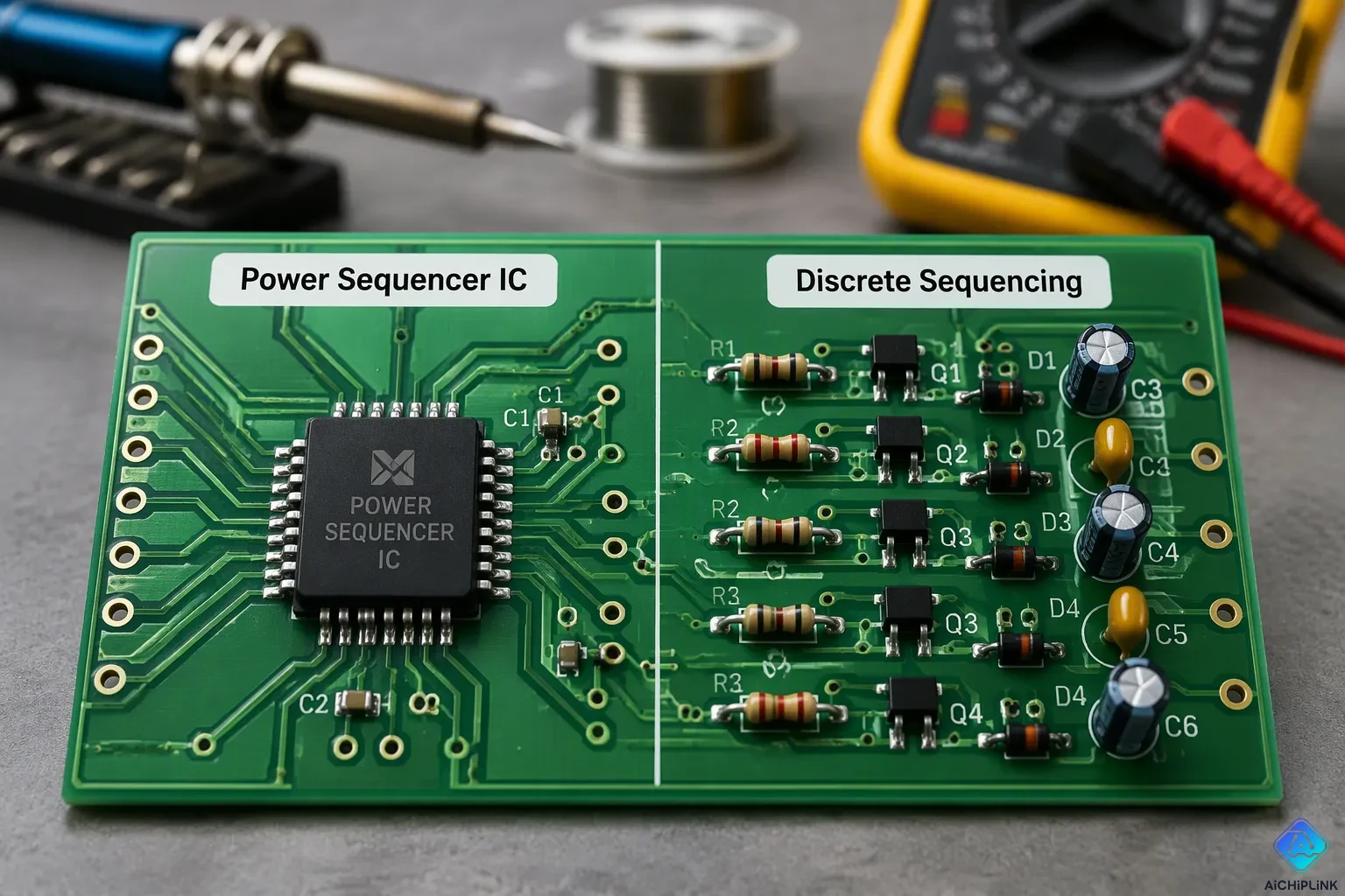
Power sequencer ICs give you an all-in-one, easy solution. Discrete sequencing gives you flexibility and lower part costs for simple sequences. Neither approach is best in every case. The right choice depends on what your system needs.
| Dimension | Power sequencer ICs | Discrete sequencing |
|---|---|---|
| Integration | Small size, built-in fault monitoring | Put together and adjusted by hand |
| Flexibility | Can be set up within the IC's features | Logic you can change completely |
| Cost | Best when BOM cost and repeatability matter | Low part cost, but more engineering work |
Designers think about technical performance, how well it fits the application, regulatory compliance, and cost. A power sequencer works well for repeatable commercial products. A discrete network works well for unique behaviors, like staggered power-up with simultaneous power-down. Each approach fits a different set of limits.
Key Takeaways
-
Power sequencer ICs give exact timing and fault reporting in a small package.
-
Discrete sequencing uses simple parts, which keeps costs low and gives you full freedom in your design.
-
Pick discrete sequencing for simple, fixed orders that use only a few rails.
-
Pick power sequencer ICs when you need many rails, flexible timing, and diagnostics.
-
Compare the total cost over the product's life, not just the price of the part.
The Role of Power Sequencing
Power sequencing means turning power rails on and off in a set order with exact timing. The purpose of a power sequencer is easy to describe but hard to carry out: each rail must reach its correct level before the next one turns on. A power sequencer timing diagram shows this plan as a series of ordered ramps. Designers depend on it to make sure a system with multiple power rails starts up and shuts down safely and reliably.
Risks of Incorrect Sequencing
Bad timing during power changes causes three main dangers: parasitic latch-up, high current stress, and digital data corruption. Latch-up needs special attention in CMOS devices. Wrong rail sequencing during power-up and power-down can set off latch-up, and special sequencing control blocks with timing generators and state machines coordinate multiple LDO outputs to enforce the right rail order. Thermal stress makes this worse, because high temperatures lower the latch-up threshold.
A level-shifter design error sent 3.3V into an FPGA I/O pin rated for 1.8V logic. The input protection clamped the voltage but could not handle the current that resulted: the pin shorted inside, creating a direct 3.3V-to-ground path. This overloaded the supply, tripped its protection circuit, and brought the whole system down—destroying the FPGA.
Data corruption follows a quieter path. Marginal signal integrity causes random bit errors that build up over time, producing occasional crashes and intermittent failures. Reliable power sequencing is needed to prevent data corruption and keep processes running in manufacturing and 5G infrastructure.
Common Multi-Rail Scenarios
Multi-rail systems use several sequencing schemes. Time-based sequencing triggers all point-of-load converters from one enable line with pre-programmed delays. Event-based sequencing chains the power-good signal of one converter to the enable of the next, which enforces strict order but needs hardware changes to alter it. Bus-based sequencing lets converters share sequence and timing over a serial bus, so firmware can change the order without touching the board. Voltage tracking instead controls the relative voltage difference between rails.
| Scenario | How It Works | Key Characteristics |
|---|---|---|
| Time-based | Common enable line with pre-programmed delays and ramp rates | Simplest scheme; timing accuracy depends on converter specs |
| Event-based | Power-good of one converter enables the next | Strict ordering; hard-wired |
| Bus-based | Converters share sequence over a serial bus | Flexible; order changeable without hardware changes |
| Voltage tracking | Controller output sets the reference for other rails | Controls relative voltage differences |
Proper sequencing is therefore a key function in any design with multiple rails. The choice of scheme shapes the power-up and power-down process, and it sets the accuracy the rest of the system can expect.
Power Sequencers Implementation Approaches
Engineers have five main ways to handle power sequencing: discrete components, load-switch-based setups, PMIC-integrated sequencing, programmable logic or mixed-signal ICs, and dedicated power sequencer ICs. Each option trades integration for flexibility in a different way. The sections below compare the two families that matter most in practice.
Discrete Component Methods
A discrete network builds the sequence from resistors, capacitors, comparators, and logic gates. An RC delay sets the wait time between rails, and a comparator checks the rail voltage before it releases the next enable. Daisy-chaining links the power-good output of one regulator to the enable of the next. Logic gates add conditions, such as holding a rail off until two supplies are both valid.
This approach suits small systems with a fixed order. The parts cost little, and the designer controls every detail of the timing. The trade-off is engineering effort. Each rail adds components, and the timing drifts with tolerance and temperature. A discrete network also reports faults poorly, because it has no central point to collect status.
Load-Switch and PMIC Methods
A load-switch-based setup needs only a single GPIO from the processor and no external IC or supervisor. The processor drives one MOSFET per rail, and the switch turns on slowly to limit inrush current and avoid voltage drops. During operation, the switch checks current and temperature, so a short or overload triggers shut-off or current limiting.
Power-management ICs and configurable mixed-signal ICs go further and build sequencing into the device itself. This makes system design simpler and cuts component count. Integration brings clear gains:
-
Better reliability
-
Exact voltage and current control that extends load lifespan
-
Lower conduction and switching losses for better efficiency
-
Longer battery operating time in portable devices
The PMIC sets the turn-on rate and timing for each rail. Sequential timing waits for the first rail to reach its nominal value. Ratiometric timing starts both outputs together with slopes that differ by a constant factor. Simultaneous start-up gives both slopes identical shapes, so the rails reach regulation at different times. Programmable power sequencers and dedicated power sequencer ICs extend this control with stored timing profiles and fault reporting.
Discrete Sequencing Explained
RC Delay and Comparator Methods
One way to build sequencing with separate parts uses the rising voltage of a first rail (VCC1) with an RC network and a comparator to make a delayed trigger. The comparator's reference voltage (VREF) sets the level where the second rail (VCC2) can turn on. VCC2 then starts after VCC1, and the RC time constant sets the delay. The comparator output drives an N-channel MOSFET, and the driver includes a charge pump. The charge pump holds VGS a few volts above VCC2, so the MOSFET is fully on and controls the second rail's turn-on time accurately. This method gives tighter control of turn-on timing than sequencing that uses only logic and Enable pins, but it needs more parts.
The same RC network controls turn-off, so VCC2 shuts down after VCC1 shuts down when VCC1 drops. The scheme also relies on VCC1 as the comparator reference, and it can fail if VCC1 is not there. Compared with logic-based sequencing, this approach needs more components: a MOSFET, a comparator, a charge pump driver, and the RC network. It still allows more accurate turn-on control in demanding applications.
Daisy-Chaining and Logic Methods
Daisy-chaining builds the order from the regulators themselves. Each regulator has a power-good (PG) output, and the next regulator has an Enable (EN) input. The designer connects the PG output of the first regulator to the EN input of the next. When the first rail reaches good, it turns on the next regulator, and the effect moves down the line. One PG output may drive multiple EN inputs, and the chain repeats for any number of DC regulators in series.
This method has clear limits. Rails must follow a strict step-by-step pattern, so the order offers little flexibility. The chain cannot add a set time delay before a rail turns on, and it cannot handle turn-off sequencing, which may matter as much as turn-on. Logic and PMIC methods fill these gaps. A power sequencer IC sets turn-on and turn-off order across multiple rails, controls ramp rates, and manages rails if one fails. Designers program delays with capacitors or set timing digitally over a bus. A power sequencer with bus timing can also daisy-chain to handle more than four rails. Discrete-component-based power sequencers still work well for fixed, simple orders, while a power sequencer IC suits systems with many rails and flexible timing needs.
Pros and Cons of Discrete Sequencing
Low Cost and Flexibility
A discrete network saves money on parts. Resistors, capacitors, comparators, and logic gates cost very little. A small system with a fixed order needs only a few of them. The designer controls every timing detail, from the RC time constant to the comparator threshold. Nothing stands between the idea and the board—no vendor tool, firmware, or configuration file.
This freedom helps with unusual behavior. A designer can build staggered power-up with simultaneous power-down. They can also hold a rail off until two supplies are both valid. A discrete solution also fits a one-off design, where the team puts engineering hours into a circuit it already knows. The trade-off is that the work grows with rail count. Each rail adds parts, and each part adds a tolerance to check.
Complexity and Limited Features
The hidden cost of discrete sequencing is engineering time. Every rail adds components, and the timing drifts with tolerance and temperature. A comparator threshold shifts, and an RC delay stretches. The order that worked on the bench may slip on a cold morning. The designer must plan for that drift across the full operating range.
Fault handling is the weaker side. A discrete network has no central point to collect status, so it reports faults poorly. Daisy-chained regulators follow a strict step-by-step pattern. The chain cannot add a set time delay or handle turn-off sequencing. A power sequencer IC fills these gaps with stored timing profiles and fault reporting. Discrete power sequencers still fit fixed, simple orders well. A power sequencer earns its place when rail count rises and timing accuracy matters. Teams that weigh both options often find the discrete approach cheaper up front and the power sequencer cheaper over a product's life.
Power Sequencer Overview: IC-Based Sequencing
A power sequencer IC puts the timing engine, the monitoring logic, and the fault handling all inside one package. This power sequencer overview covers what that integration delivers. Programmable power sequencers let designers customize power-up and power-down patterns. Users can set the exact sequence, timing, voltage, and current levels for individual components or groups. This control suits complex systems where components have specific requirements and dependencies. Teams can build such a device from an MCU, an FPGA, or a configurable mixed-signal IC.
Programmable Timing and Monitoring
A programmable mixed-signal IC can be set up and set up again to perform specialized analog measurements within a programmable matrix. The idea is like an FPGA for digital logic. This programmability makes sensing and control tasks in power sequencing simpler by putting most analog processing into a single package. The subsystem may then shrink to just a system host (MCU or FPGA) and the mixed-signal IC. Spare GPIOs on the mixed-signal IC or the host can trigger system resets, provide fault indicators, or toggle peripherals sensitive to supply fluctuations. A programmable power sequencer can also run on its own, with its serial interface broken out to a connector for programming, so no MCU or FPGA is required. The GreenPAK family from Renesas is one example, with hardware components and software solutions that speed mixed-signal applications like power sequencing and monitoring.
Fault Handling and Reporting
A dedicated sequencing controller watches every rail and reports what went wrong. The device monitors and reports undervoltage and overvoltage conditions, generates microprocessor reset signals, and reports the type and source of faults to aid diagnosis. Individual channel controls let engineers exercise enable outputs and supervisory functions independently. Built-in output protections cover over-voltage, over-temperature, over-current, and under-voltage lockout, which keeps operation safe under abnormal conditions. Full performance monitoring and reporting come standard, and an SMBus-compliant I2C interface allows local or remote reconfiguration. These features support advanced power sequencing, where the power sequencer timing diagram must hold across faults, not just during normal startup. Precise power-up and power-down timing then becomes a verified property of the design.
Pros and Cons of Power Sequencer ICs
Integration and Accuracy
A power sequencer IC puts the timing engine, voltage supervisors, and fault logic into one package. One PMIC can take the place of six separate power ICs with a single chip. It also makes the bill of materials smaller by using fewer passives and smaller inductors and capacitors. High switching frequencies like 2.3 MHz help with this. The result is up to about 60% savings in power-solution size compared to a discrete design. This often comes in a compact 5x5 mm² or 4x4 mm² package.
| Aspect | Power sequencer IC | Discrete solution |
|---|---|---|
| Integration | Sequencer and supervisors in one PMIC | About six extra components for a daisy chain |
| Size | Up to ~60% smaller power solution | Larger layout from extra ICs and passives |
| Timing | Greater precision and customization | Less control and precision |
| Monitoring | On-chip over/under-voltage and fault flags | No comparable on-chip diagnostics |
Timing accuracy is the strongest reason to choose these parts. A power sequencer IC gives you greater precision and customization of the power-up and power-down sequence. In some systems, that precision matters more than less PCB area and lower cost. Fault handling adds a reliability advantage. On-chip supervisory functions check for over-voltage and under-voltage conditions, raise fault flags, and drive safe state transitions. A programmable power sequencer stores these settings in built-in memory and lets you reprogram them over I2C, so the processor can read back status.
Cost and Flexibility
The trade-off is higher cost and less flexibility than a discrete network. A power sequencer costs more per part than a handful of resistors and comparators. Its sequence also stays within the features the vendor provides. A designer cannot rewire the logic the way a discrete circuit allows.
The picture changes with the implementation. An MCU-based approach offers high flexibility and easy digital integration, but it brings higher cost, complexity, slower latency, and higher current consumption. Configurable mixed-signal ICs balance both sides: low cost, high flexibility, low power, low latency, and a small footprint. Buyers who compare power sequencer ICs against simple discrete chains should weigh part price against engineering hours and long-term reliability. For many multi-rail products, the integrated part wins on total cost of ownership.
Comparing the Two Approaches
Performance and Fit
Performance shows clear differences between the two approaches. A power sequencer IC keeps timing accurate across temperature and part differences. Its delays come from an internal clock, not an RC network. A resistor-capacitor chain drifts as comparator levels shift and capacitors age. The power sequencer timing diagram stays fixed in silicon or stored settings. A component-based design redraws that diagram with every part change. Each revision needs a new bench check. Power-up and power-down timing must hold across faults, not just during a clean start.
Fit depends on rail count and sequence complexity. A two-rail board with a fixed order works well with a passive network. The parts cost little, and the designer controls every detail of the ramp. A board with many rails and flexible timing needs a power sequencer. Programmable parts store timing, voltage, and current levels for each rail. They replay them on command. They also handle turn-off order, which a daisy chain cannot do. A daisy chain follows a strict step-by-step pattern. It cannot add a set delay before a rail turns on.
Fault response is another divider. A power sequencer IC watches each rail, flags undervoltage and overvoltage, and drives a safe state. A passive network has no central point to collect status. So a fault shows up as a dead board, not a reported code. A reported code shortens debug time and helps field service. Teams that need diagnostics for multiple power rails should weigh this gap carefully. The gap grows as rail count rises, because each rail adds another point to watch.
Compliance and Cost
Regulatory work changes the comparison. In a functional safety design, the architect must pick diagnostics to reach the target SIL or PL. They must also evaluate the architecture with an FMEDA. Watching power supplies across multiple rails (e.g., 1.8V, 3.3V, 5V, 9V, 14.7V, -5.7V) is hard. Vendors present a single-chip supervisory/sequencing device such as the ADM1169 Super Sequencer as a solution. It handles supply monitoring and sequencing under IEC 61508 / SIL requirements. So the compliance path for power sequencing favors an integrated part when the safety case demands per-rail diagnostics.
EMC compliance adds its own demands, and the choice of approach shapes them:
-
Switching noise from PMICs can interfere with sensitive analog circuits or cause failures in radiated emissions testing.
-
Proper ground plane design with minimal slot cuts helps reduce this interference.
-
An EMI filter at the PMIC input cuts conducted noise.
-
Spread spectrum switching spreads noise energy across frequency ranges to ease EMC compliance.
Cost tells a split story. Discrete parts cost less up front, and power sequencer ICs cost more per unit. Engineering hours reverse that math. A passive network grows with each rail. Every added part brings tolerance checks and test time. A power sequencer IC takes that work into one configured part. Proper sequencing then becomes a verified property, not a bench experiment. Teams should compare total cost of ownership, not part price alone. A simple product with a fixed order may never repay the price gap. A complex product with many rails usually does. So the comparison comes down to the product, not the part.
Choosing a Power Sequencer Approach
The final choice is about matching the circuit to the system. Engineers should list the rail count, the needed order, the timing tolerance, and the fault-reporting needs before they pick a part. That list settles most debates quickly.
When Discrete Sequencing Fits Best
A discrete network suits a small board with a fixed order. Two or three rails that always start in the same sequence need little more than an RC delay and a comparator. The parts cost very little, and the designer controls every detail of the ramp. A one-off design also fits this path well. The team already knows the circuit, and the engineering hours go into a layout it trusts.
Unusual behavior favors the discrete route too. A designer can build staggered power-up with simultaneous power-down, or hold a rail off until two supplies are both valid. No vendor tool or configuration file stands in the way. A single discrete chain also makes sense when the product will never ship in volume. The part price stays low, and the timing drift stays inside the bench margins the team has already checked.
The limits appear as the rail count rises. Each rail adds parts, tolerance checks, and test time. A daisy chain cannot add a set delay or handle turn-off order. Faults show up as a dead board, not a reported code. Teams should move away from this approach once diagnostics or flexible timing enter the power sequencing requirements.
When a Sequencer IC Fits Best
A power sequencer IC earns its place when many rails need exact timing. Its delays come from an internal clock, so the order holds across temperature and part differences. A power sequencer also stores timing, voltage, and current levels for each rail and replays them on command. That repeatability matters in commercial products that ship in volume.
Diagnostics tip the balance further. A power sequencer watches each rail, flags undervoltage and overvoltage, and drives a safe state. Field service then reads a code instead of guessing. Safety programs push the same way. Per-rail monitoring supports the diagnostic coverage a functional safety case demands, and proper sequencing becomes a verified property rather than a bench experiment.
Cost decides the rest. A power sequencer costs more per unit than a handful of passives. The engineering savings often repay that gap on complex boards. Teams should compare total cost of ownership, not part price alone. A simple product may never repay the difference. A complex product usually does. Either way, the choice should follow the system, not habit.
Choosing between integrated and discrete sequencing is really a trade-off. Power sequencer ICs give you integration, timing accuracy, and fault reporting. Discrete networks give you low part cost and full design freedom. Neither approach wins in every case.
Engineers should use five factors to guide the decision: sequence complexity, rail count, timing accuracy needs, fault-handling requirements, and budget. A simple board with a fixed order rarely needs an integrated part. A complex multi-rail design usually does. Teams that match the approach to real system limits avoid paying for features they don't use. They also avoid shipping a circuit that cannot report its own faults. A power sequencer earns its place when the requirements call for it.

Written by Jack Elliott from AIChipLink.
AIChipLink, one of the fastest-growing global independent electronic components distributors in the world, offers millions of products from thousands of manufacturers, and many of our in-stock parts is available to ship same day.
We mainly source and distribute integrated circuit (IC) products of brands such as Broadcom, Microchip, Texas Instruments, Infineon, NXP, Analog Devices, Qualcomm, Intel, etc., which are widely used in communication & network, telecom, industrial control, new energy and automotive electronics.
Empowered by AI, Linked to the Future. Get started on AIChipLink and submit your RFQ online today!
Frequently Asked Questions
What does a power sequencer actually do?
It turns power rails on and off in a set order with controlled timing. Each rail reaches its target level before the next one starts. This order prevents latch-up, current stress, and data corruption during power transitions.
Can a simple RC network replace a dedicated sequencing IC?
Yes, for a small board with a fixed order. An RC delay and a comparator set the wait between rails at low part cost. The timing drifts with tolerance and temperature, though, and the network reports no faults.
Why does a daisy chain limit design options?
A daisy chain links each power-good output to the next enable input. The rails must follow a strict step-by-step pattern. The chain cannot add a set delay before a rail turns on, and it cannot handle turn-off sequencing.
How does a power sequencer improve fault diagnosis?
It watches every rail and flags undervoltage and overvoltage conditions. It reports the type and source of a fault, so field service reads a code instead of guessing. A passive network shows only a dead board.
Which approach costs less overall?
Discrete parts cost less up front. Engineering hours reverse that math as rail count rises. A power sequencer costs more per unit, but it often repays the gap on complex boards. Compare total cost of ownership, not part price.