What is FIR Filter?
A home theater receiver shapes sound using equalizers, crossovers, and room correction. These tools quietly adjust audio without standing out. What is FIR Filter? It often does this job behind the scenes. It is a digital filter whose impulse response settles to zero in limited time. This means the filter reacts to a signal and then stops fully. Engineers like this predictable behavior. They ask: what is FIR Filter, and why does it matter for audio? The answer shows a strong tool for controlling sound with precision and steadiness.
Key Takeaways
-
An FIR filter stops reacting after a fixed amount of time. This feature gives engineers steady control over sound.
-
FIR filters do not use feedback. This makes them steady and easy to predict for audio processing.
-
Symmetric coefficients give FIR filters a linear phase. This keeps all frequencies arriving at the same time, which preserves sound quality.
-
FIR filters need more computing power than IIR filters. This causes a delay, so they are less useful in live sound.
-
Engineers choose FIR filters for room correction and crossovers. They pick IIR filters when low latency matters.
What Is an FIR Filter?
Finite Impulse Response Explained
An FIR filter is a digital filter that settles to zero in a set amount of time. That one feature gives this type of filter its name. In signal processing, a finite impulse response filter reacts to a limited input and then stops all at once. The response does not fade away forever. It just ends.
The order of the filter decides how long that response lasts. The impulse response of an Nth-order discrete-time FIR filter lasts exactly N+1 samples, from the first nonzero element to the last nonzero element, before it settles to zero. A tenth-order design, for instance, finishes its work after eleven samples. Nothing stays past that point.
This behavior sets FIR apart from IIR designs. An IIR filter may keep responding forever, usually by decaying. A finite impulse response ends on a known schedule.
| Filter Type | Impulse Response Duration |
|---|---|
| FIR | Becomes exactly zero after a finite time; the response has finite duration. |
| IIR | Does not become exactly zero past a certain point; it continues indefinitely. |
Think of a fingerprint that fades away completely. Once the last trace is gone, the surface goes back to how it was. An FIR filter works the same way. After an impulse moves through the tapped delay line, the system keeps no more memory of it. The response past that point is exactly zero.
Nonrecursive and Feed-Forward
Engineers also call this setup nonrecursive. The filter uses no feedback from earlier outputs. Each output sample depends only on the current input and past inputs. The structure is feed-forward only.
FIR filters are described as having no feedback loops, with their output depending only on the sum of current and past input values.
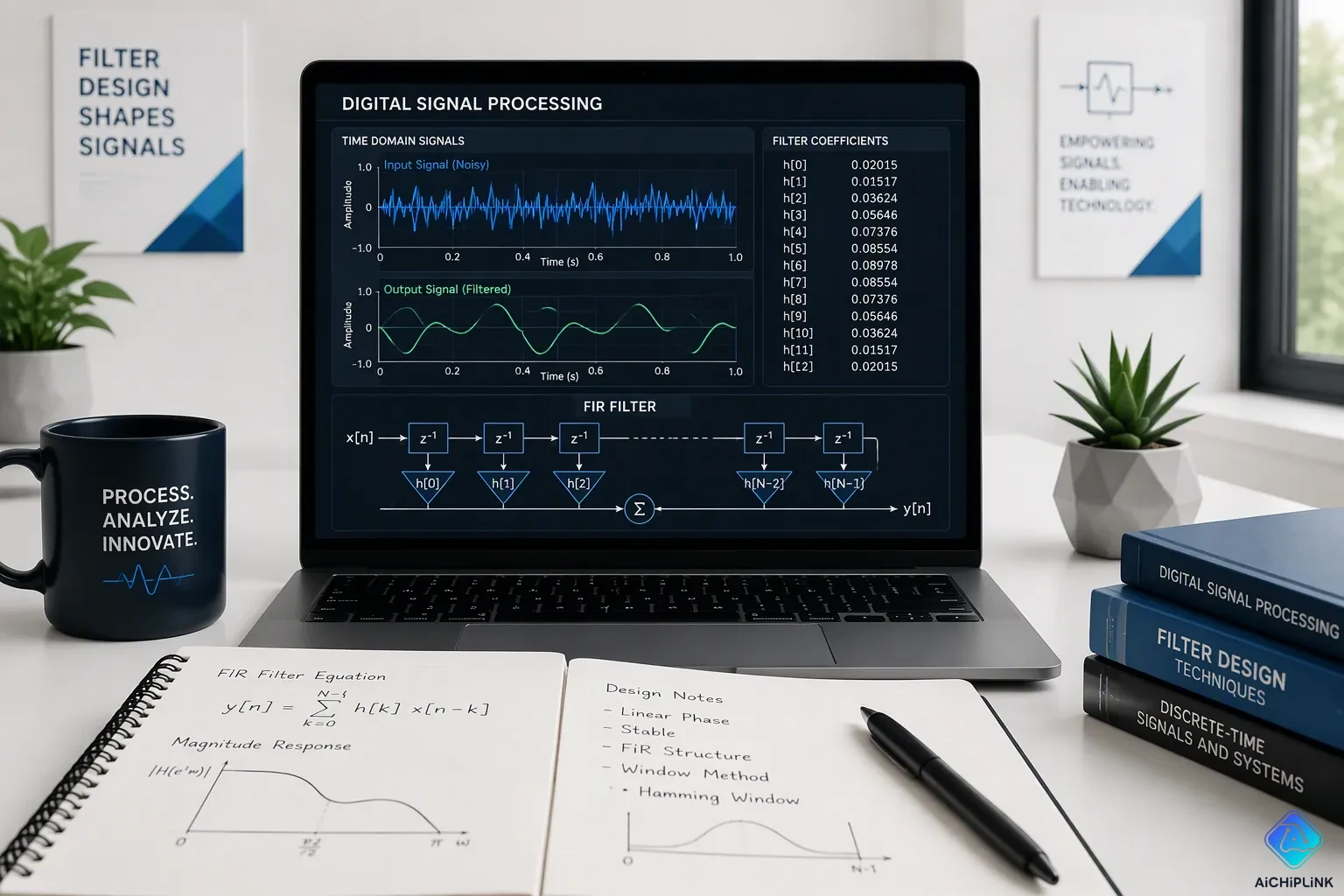
A direct-form FIR structure is built from delay blocks, constant multiplications, and additions. Input samples are delayed, multiplied by coefficients, and added to make the output. The transposed direct-form flips the coefficient order and puts delays after multiply-accumulate operations, which shortens the critical path and fits pipelined hardware.
This feed-forward nature explains why FIR filters are stable. There is no feedback path to boost errors or push the system into oscillation. The output always stays bounded.
So what is FIR filter behavior in simple terms? The filter reads a window of input samples, weights each one, and adds the results. Then it moves to the next sample. What is FIR filter design really about? Picking those weights well. What is FIR filter appeal for audio? Predictable, stable, and precise control over sound.
How FIR Filters Work
Multiply, Add, and Sum
An FIR filter uses one easy process: multiply and add. The filter keeps a set of coefficients and a window of recent input samples. For each new sample, it multiplies each input by its matching coefficient. Then it adds all those products into one number. That number becomes the output sample.
This operation is an inner product between the coefficient vector and the input vector. The math looks like this:
The convolution output y[n] for a filter of length N_h is the inner product of the input vector x[n..n+N_h-1] and the coefficient vector c[0..N_h-1]. That is, y[n] = sum_{k=0}^{N_h-1} x[n+k] * c[k].
Real-time DSP code almost never runs that loop one tap at a time. A common trick unrolls the inner loop and handles several elements at once:
-
The inner loop handles 4 elements at a time.
-
It figures out partial inner products: x[i+j]*c[j] + x[i+j+1]*c[j+1] + x[i+j+2]*c[j+2] + x[i+j+3]*c[j+3].
-
These partial sums build up to form the output sample y[i].
Modern DSP chips make this multiply-add cycle fast. A dedicated Multiply-Accumulate pipeline runs the core operation Y = (A × B) + C in one clock cycle. Zero-overhead looping repeats the tap-iteration code without extra branch cycles. Saturation arithmetic clamps overflow values to the register ceiling instead of wrapping, which stops harsh digital clipping during FIR filter math overflow.
| Hardware Feature | How It Optimizes Multiply-Add for FIR Filtering |
|---|---|
| Harvard architecture | Separate memory buses allow simultaneous instruction fetch and data read/write in one clock cycle. |
| Dedicated MAC pipeline | Executes Y = (A × B) + C in a single clock cycle. |
| Zero-overhead looping | Repeats tap-iteration code without extra CPU cycles for branch checks. |
| Saturation arithmetic | Clamps overflow to the register ceiling instead of wrapping. |
| Fixed-point vs floating-point | 24-bit fixed-point DSPs deliver ~144 dB dynamic range; floating-point DSPs provide >1,500 dB. |
The Impulse Response Fingerprint
The coefficient set defines everything about the filter. Feed one impulse into the system, and the output traces out those coefficients in order. That output is the impulse response. It works like a fingerprint for the filter.
The impulse response and the frequency response form a matched pair. One describes behavior in time. The other describes behavior across the audio spectrum. A long impulse response shapes low frequencies with fine detail. A short one reacts quickly and affects higher frequencies. Engineers read the impulse response to predict how the filter will color sound. They shape the coefficients to sculpt the frequency response they want. This time-frequency link gives FIR filters their power for precise audio control.
Designing FIR Filters
Coefficients as the Recipe
A group of numbers makes up the heart of every filter of this kind. Engineers call these numbers coefficients or taps. They decide how the filter shapes sound. The coefficients are the exact impulse response samples. For instance, the coefficients directly form the impulse response. These values directly set the magnitude and phase of the frequency response.
Symmetric coefficients give a special bonus. When the values mirror each other around a center point, the filter gets linear phase. Linear phase means all audio frequencies have the same delay. This property keeps the waveform shape intact. Music and speech stay accurate without time smearing.
Engineers use special tools to compute these coefficients. Some tools compute coefficients from impulse response measurements, while others apply high-resolution FIR filters for amplitude and phase correction, and still others use FIR filters for time domain correction to align sound waves from all speakers.
Truncating the Ideal Response
An ideal FIR filter needs an infinite impulse response. Designers begin with that perfect shape. They then cut it off to a practical length. This truncation brings problems.
A sudden cut causes ringing in the passband and poor stopband attenuation. Engineers call this the Gibbs effect. The worst ripple shows up at the transition between passband and stopband. Just using a longer response does not fix this issue. The discontinuity at the cut stays significant.
Window functions fix this problem. A window gently shapes the truncated response. Designers begin with an infinite ideal response. They multiply it by a window to get a finite response. They shift the result to make it causal. Common windows include Hamming, Hanning, and Blackman. Each gives different trade-offs.
Applying a length-51 Hamming window greatly reduces ringing artifacts. This benefit comes with trade-offs. The transition band gets wider. The design no longer minimizes integrated squared error. When no window is given in the fir1 function, a Hamming window is applied by default.
The window directly controls the frequency response. The main lobe width sets the transition bandwidth. The side lobe amplitude sets the stopband attenuation. Designers pick a window that balances these factors for their specific application.
FIR vs. IIR Filters
Stability and Phase Control
Stability is the biggest difference between these two designs. An FIR filter has no feedback path, so its output depends only on current and past inputs. This structure makes it stable under all conditions. Coefficient values cannot push it into oscillation. An IIR filter has a feedback loop, so its poles must stay inside the unit circle. Fixed-point quantization can move a pole onto that circle, and the output then grows without bound.
| Stability Aspect | FIR Filter | IIR Filter |
|---|---|---|
| Mechanism | Non-recursive, feedforward only | Recursive, includes feedback loop |
| Inherent Stability | Stable under all conditions | Requires careful pole placement |
| Quantization Risk | No stability risk | Can cause oscillation or divergence |
| Failure Mode | Graceful degradation | Catastrophic, exponentially amplified output |
Rounding IIR coefficients can move a pole onto the unit circle, making the impulse response grow without limit.
CPU Cost in Audio Gear
Computation is the price of that stability. An IIR filter typically requires far fewer multiply-accumulate operations per sample than an equivalent FIR design. That gap shapes real product decisions.
Modern hardware closes part of the distance. Some high-performance DSP processors can handle tens of thousands of FIR taps at high sample rates, while consumer DSP products might manage a few thousand taps. Loudspeaker processors and DSP amplifiers still favor IIR when battery life or cost dominates. Engineers choose FIR when the frequency response and phase behavior justify the load.
Trade-Offs of FIR Filters
Latency and Group Delay
The biggest real-world downside of an FIR design is latency. A linear-phase design delays every frequency by the same amount, so all frequencies reach the output at the same time. This steady group delay keeps the waveform shape unchanged, but it adds a fixed delay equal to half the filter order. The stronger the design, the longer the delay. A long room correction filter can add tens of milliseconds. In live sound or two-way monitoring, that delay causes real problems.
Minimum-phase IIR designs have lower total delay, but their group delay changes with frequency and peaks near the cutoff. This change causes phase distortion that blurs transients. Linear-phase designs avoid group delay changes, but they pay for that with higher latency. The steady delay of linear-phase designs keeps all frequency parts in their original time order, which preserves waveform shape for accurate stereo imaging and transient reproduction.
As one source notes, a minimum-phase filter like a crossover or high-pass filter is the main source of group delay. Minimum-phase high-Q PEQs add even more group delay. Linear-phase designs avoid group delay, but the steady delay comes at the cost of higher latency.
When FIR Isn't the Answer
Latency makes FIR filters a poor fit for some real-time uses. Live sound systems, in-ear monitors, and video conferencing gear cannot handle delays above a few milliseconds. Those devices must use IIR designs to keep latency low. Computational load also limits the use of such designs. A design with many taps needs a lot of DSP power. In battery-powered gear or low-cost processors, IIR gives the same magnitude frequency response with far fewer operations.
Engineers pick IIR when the application cares more about low delay, low power, or low cost than linear phase. If the signal must stay time-aligned, a linear-phase design becomes necessary despite the latency cost. For example, a live sound engineer cannot afford the delay a room correction filter adds. Instead, they use IIR equalizers that add very little latency. In recording studios, where latency matters less, FIR designs correct both amplitude and phase for accurate monitoring. The trade-off between steady group delay and lower latency defines the choice.
An FIR filter is a digital filter with an impulse response that ends after a finite number of samples. This type of filter provides stability, precise phase control, and flexible frequency response shaping. These advantages of the filter justify the costs of latency and CPU load. Engineers choose FIR over IIR when they need linear phase and predictable behavior. Room correction and crossover designs benefit from its precision. A live sound system, with strict latency limits, still relies on IIR instead. FIR filters continue to play a lasting role in modern audio. Their ability to shape sound without instability makes them essential for high-fidelity signal processing.

Written by Jack Elliott from AIChipLink.
AIChipLink, one of the fastest-growing global independent electronic components distributors in the world, offers millions of products from thousands of manufacturers, and many of our in-stock parts is available to ship same day.
We mainly source and distribute integrated circuit (IC) products of brands such as Broadcom, Microchip, Texas Instruments, Infineon, NXP, Analog Devices, Qualcomm, Intel, etc., which are widely used in communication & network, telecom, industrial control, new energy and automotive electronics.
Empowered by AI, Linked to the Future. Get started on AIChipLink and submit your RFQ online today!
Frequently Asked Questions
What makes an FIR filter different from other digital filters?
An FIR filter stops responding after a set number of samples. Other designs, like IIR, keep going forever. This limited response gives engineers behavior they can predict. They know exactly when the filter stops working. That certainty helps in audio systems where timing and stability matter.
Why do audio engineers choose FIR filters for room correction?
Room correction needs exact control over both amplitude and phase. FIR filters give linear phase when their coefficients are symmetric. This keeps all frequencies lined up in time. The frequency response stays accurate without blurring transients. Engineers trust this precision for high-fidelity playback in studios and home theaters.
Can FIR filters cause problems in live sound?
Yes. Latency is the main issue. A linear-phase design delays all frequencies by half the filter order. Long correction filters add tens of milliseconds. Live sound cannot handle that delay. Engineers use IIR equalizers instead for low-latency monitoring and in-ear systems.
How many taps does a typical FIR filter need?
Tap count depends on the job. A simple crossover may need a few hundred. A detailed room correction filter can require thousands. More taps mean finer frequency control but higher CPU load. Engineers balance tap count against available DSP power and acceptable latency.
Are FIR filters always the best choice for audio gear?
No. FIR filters offer stability and phase control, but they cost CPU power and add latency. Battery-powered devices and budget processors often favor IIR. Engineers pick FIR when linear phase and precise frequency shaping justify the trade-offs. The application decides the right tool.