How to Calculate and Choose a Precharge Resistor for High-Voltage DC Systems
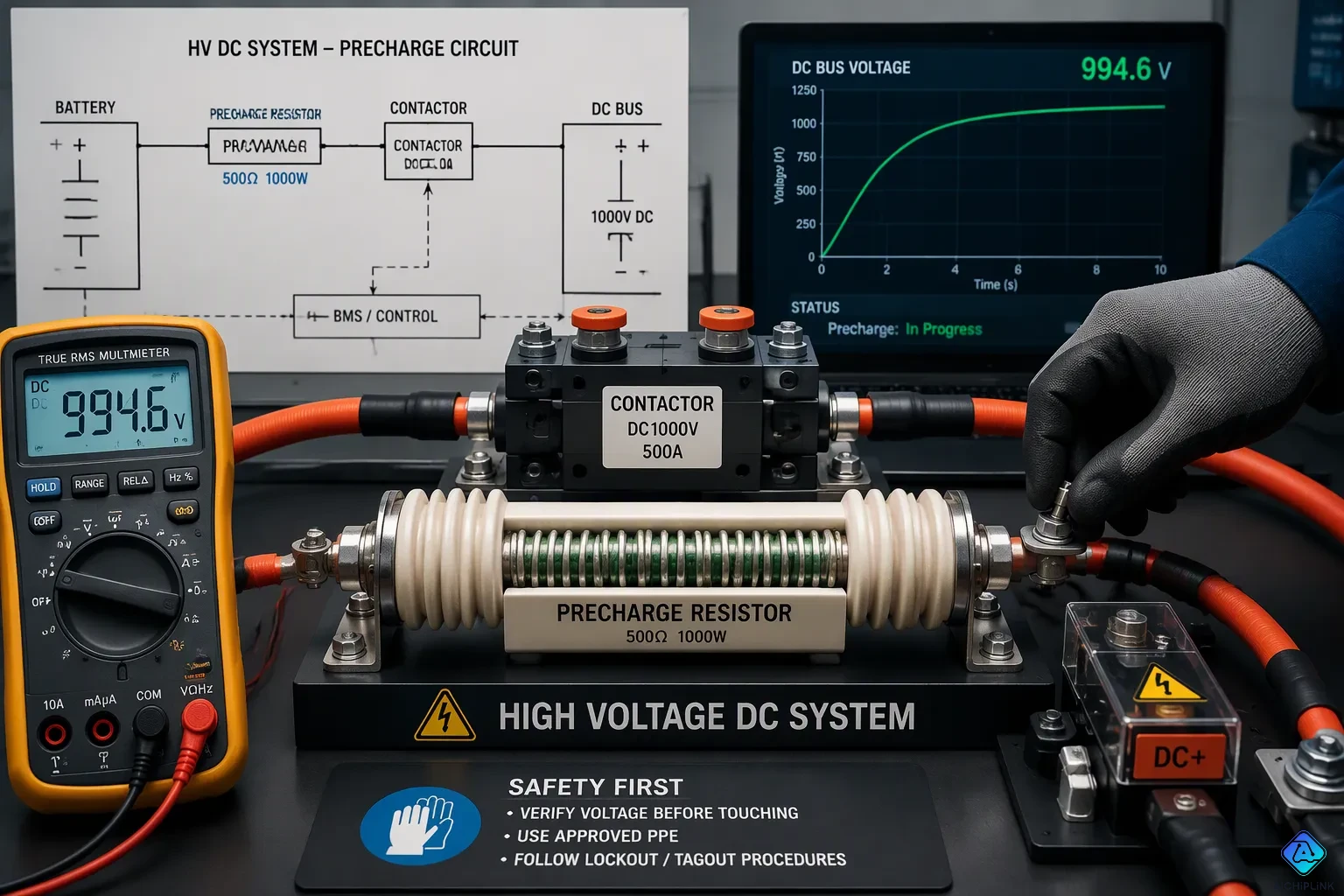
You can find the size of a precharge resistor with a simple formula: R = t / (5C). You need three values—capacitance (C), system voltage (U), and your desired charging time (t).
Then check six selection criteria: resistance value, peak current, pulse energy rating, power rating, voltage rating, and thermal derating.
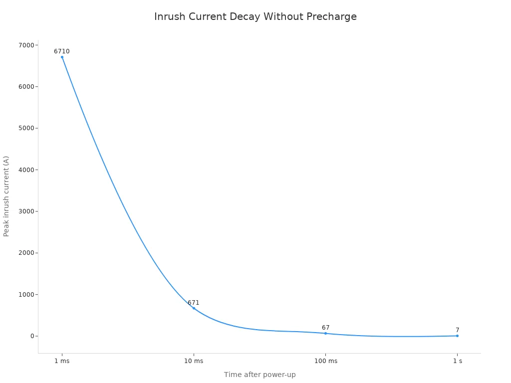
This matters because the surge can weld contactors, blow fuses, and damage capacitors in high-voltage dc systems. Above 48 V, connecting a supply directly to an uncharged capacitor bank can produce tens of kiloamperes of inrush current.
| Time after power-up | Peak inrush current (610 V source, 11,000 μF) |
|---|---|
| 1 ms | 6710 A |
| 10 ms | 671 A |
| 100 ms | 67 A |
| 1 s | 7 A |
A correctly chosen precharge resistor limits that surge.
Key Takeaways
-
Use the formula R = t / (5C) to find the precharge resistor value. You need the capacitance, the voltage, and the charging time you want.
-
Precharge stops huge inrush currents. These currents can weld contactors, blow fuses, and damage capacitors.
-
When you pick a resistor, check six things: resistance, peak current, pulse energy, power rating, voltage rating, and thermal derating.
-
A passive precharge circuit with a fixed resistor is simple and cheap. Active control makes it safer but costs more.
-
Fix startup problems by checking the voltage. 0 V means the circuit is open. Half voltage means a load is on. 90–95% voltage means the main contactor has failed.
Why Precharge Matters in HV DC Systems
The Inrush Current Problem
A capacitor bank acts like a short circuit the moment you connect it to a voltage source. The dc-link capacitors in an inverter sit empty before startup. If you close the main contactor directly, the supply sees almost no resistance. The dc-link capacitor inrush current spikes within milliseconds.
This surge flows through the contactor tips, the fuse, and the capacitor terminals. The current drops as the capacitor charges, but the first moments carry the most stress. A precharge resistor placed in series limits that first rush of current. The capacitor then charges on a controlled curve instead of a near-instant jump.
Risks of Skipping Precharge
Uncontrolled inrush current can be 20–100× higher than the rated current of your contactors. That level of stress causes instant hardware damage and a high risk of contact micro-welding. A welded contactor may never open again, and the system loses its safety disconnect.
| Condition | Effect on contactors |
|---|---|
| No precharge (unmitigated inrush) | Inrush currents can exceed rated current by 20–100×, causing instantaneous hardware degradation; high risk of contact micro-welding |
| With precharge (normal operation) | Extremely low risk of contact micro-welding |
Fuses face the same threat. A fast surge can blow a fuse rated for steady operation, and you get a failed startup instead of a working system. The capacitor itself also suffers. Repeated high-current hits stress the dielectric and shorten its service life.
Precharge circuits solve this problem with a simple sequence. A precharge contactor and a current-limiting precharge resistor charge the downstream components first. The voltage ramps up in a controlled way. This protects sensitive electronics and extends the operational lifespan of both the contactors and the downstream parts. In high-voltage dc systems, that controlled ramp is the difference between a reliable startup and a damaged power stage.
Precharge Resistor Calculation
How to Calculate a Precharge Resistor
Begin with the RC time constant. The rc time constant is R × C, where R is the total charging-path resistance in ohms and C is the dc-link capacitor value in farads. The capacitor gets to about 99% of the supply voltage after five time constants. Keep the precharge contactor closed for that whole window, so the capacitor charges fully before the main contactor closes.
You can figure out a precharge resistor from the charging time alone: R = t / (5C). Here t is the precharge time you want, in seconds. This is the heart of any precharge resistor calculation, and it gives you the calculated precharge resistance for the rc charging path.
A worked example makes the steps clear. Take an 800 V system with a 1000 µF dc-link capacitor and a 1 s target time. The time-based value is R = 1 / (5 × 0.001) = 200 Ω. Now check the current limit. If you want the starting precharge current capped at 6 A, then R = 800 / 6 = 120 Ω. Your working range is 120 Ω to 200 Ω. The first resistor power at the start is U² / R, which is 800² / 200 = 3200 W at the 200 Ω value. That spike lasts only a moment, so the resistor needs a strong pulse rating rather than a big heat sink.
Measured data backs up these numbers. A dc-link capacitor charged through about 100 mΩ of total resistance shows a peak surge near 500 A, and full-bandwidth probes record peaks above 350 A.
| Peak current value | Measurement condition |
|---|---|
| ~500 A | Derived from R-C charging equations (total resistance ~100 mΩ) |
| >350 A | Observed with full bandwidth |
| >300 A | Observed in bandwidth-limited measurement |
Energy and Power Formulas
The precharge resistor formulas below cover the three stress levels you must check. Use them together, because each one sizes a different part of the resistor datasheet.
-
Energy dissipated in the resistor: E = ½ × C × U², in joules. A 100 V battery with 10,000 µF stores 50 J.
-
Average power during precharge: P = E / t, in watts. The same 50 J over a 500 ms precharge gives 100 W.
-
Instantaneous power at the start: P = U² / R. At 100 V and 10 Ω, that is 1000 W.
The pulse energy per charging cycle drives the withstand check. In the 800 V example, E = ½ × 0.001 × 800² = 320 J per cycle. Apply a safety margin of 1.5× to 2× to both the energy and power ratings, and base the calculation on the fully charged maximum battery voltage, not the nominal value. A precharge calculator or spreadsheet speeds up design iterations for HV dc-link capacitors, since one change in C or t shifts every result.
Precharge Resistor Sizing Checklist
Key Technical Parameters
A good precharge resistor calculation gives you a starting value. How you size the precharge resistor then depends on how that value holds up in real operating conditions. Check each parameter below before you commit to a part.
| Selection Parameter | What to Verify |
|---|---|
| Resistance and tolerance | Initial current stays within limits while still reaching the required DC-link voltage before contactor closing |
| Pulse energy | Single-pulse and repetitive-pulse capability exceed the calculated precharge energy |
| Peak power | Resistor withstands the initial power pulse for the required duration |
| Working voltage | Resistor or resistor network withstands the maximum startup voltage |
| Pulse duration | Manufacturer's pulse curve supports the expected normal and fault-duration pulse |
| Restart interval | Repeated starts allow sufficient thermal recovery or stay within repetitive-pulse limits |
| Thermal derating | Ratings remain adequate at the highest expected ambient and enclosure temperature |
| Cooling | Mounting, heatsinking, airflow, and thermal-interface requirements are satisfied |
| Insulation | Creepage, clearance, terminal spacing, and insulation suit the system voltage |
| Environmental requirements | Package and mounting suit vibration, shock, humidity, contamination, and enclosure conditions |
Run the sizing equations from the previous section against the worst case, not the nominal case. The main selection factors are resistance, pulse energy, voltage rating, charging time, temperature, and restart frequency. The resistor must also match the capacitor size, bus voltage, mounting, and cooling conditions.
Application Fit and Cost
Your system voltage and capacitance set the practical window for precharge resistor selection. A 400 V bus with 500 μF works with a 20 Ω resistor, a 10 ms time constant, and a 40 ms precharge time. An 800 V bus with 2000 μF needs 40 Ω, an 80 ms time constant, and a 320 ms precharge time. Both cases keep the inrush current target below 20 A. You get the value from R = V0 / (20 A), so the part adapts to your measured voltage and capacitance.
Cost often decides the architecture. A single fixed precharge resistor of 10 Ω at 400 V, timed by a profile that closes the main contactor when dV/dt drops below 5 V/ms (current under 20 A), adds about $0.5 and needs zero active components. An active control approach adds about $8 and multiple active components. The fixed-resistor precharge circuit wins on cost and component count while still meeting the inrush limit.
For a two-path design, Path A covers 400 V and 500 μF with a single 50 Ω / 10 W resistor and a 10 A relay. Path B covers 800 V and 2000 μF with a 100 Ω / 25 W resistor and a 20 A relay. Together they span 400–800 V and 500–2000 μF, hold inrush below 20 A, and give relay life above 5000 cycles. This approach adds five components versus one active control solution, but each path is narrowly optimized for its range.
Resistor Types and Precharge Methods
Resistor Types Compared
Each resistor family does a different part of the precharge job. Wirewound resistors take high pulse energy well and handle short overloads. They work well for large dc-link capacitor banks that store a lot of energy. Aluminum-housed resistors spread heat into a metal case and mount easily to a chassis or heatsink. They fit designs that need steady thermal derating in a sealed enclosure. Thick-film and ceramic power resistors are small and handle voltage well. They work well on space-limited boards with moderate energy per cycle.
Your precharge resistor selection should match the part to the pulse, not just the ohms. Check the manufacturer's pulse curve against your calculated energy and duration. A part with the right resistance can still fail if its pulse rating falls short. Also confirm the precharge contactor and the precharge relay carry a voltage rating for the full battery or system voltage, not just the bus nominal.
Passive vs. Active Precharge
A passive precharge circuit uses a fixed resistor and a timed relay sequence. You close the precharge contactor, wait for the charging window, then close the main contactor. This approach is simple, low-cost, and needs no control logic. It fits most fixed-voltage systems where the capacitance and bus voltage stay stable.
An active method adds voltage sensing and control. You monitor load-side voltage during precharge to confirm the capacitor is charged before the main contactor closes. The controller blocks the main contactor until the dc-link capacitor reaches a set threshold. This protects against a stuck relay, a wrong resistor value, or a fault that slows charging. Active control costs more and adds components. Choose it when safety interlocks or variable bus voltages matter. Either way, verify the precharge resistance and sizing against the worst-case restart interval.
Troubleshooting Precharge Problems
Symptoms and Fixes
A failed startup often comes down to one of three meter readings. Each reading points to a different part of the precharge circuit. So measure first, and replace parts second.
| Symptom / Meter Reading | Likely Cause | What to Check |
|---|---|---|
| 0 V throughout startup | Open precharge loop (blown fuse or open precharge resistor) | Check the precharge fuse and resistor for continuity; make sure the precharge relay coil has power and closes |
| ~½ pack voltage, then stalls | HV load still active or sticking/intermittent precharge relay | Make sure HV accessories (heater, A/C, charger, compressor) are off; look at the relay for welded or partial contacts and check for leakage or a short |
| ~90–95% pack voltage but still faults | Main positive contactor fails to close | Test the main + contactor coil voltage and resistance; check the control signal; replace the contactor if it will not close |
A reading near half the pack voltage usually means a load is draining the bus while you charge it. Turn off every HV accessory and try the startup again. A reading that climbs to about 90–95% and then faults tells you the capacitor charged fine. The problem is in the main contactor, not the resistor.
Verification and Testing
To confirm a precharge resistor failure, power down and discharge the capacitors first. Then measure the resistor's resistance. It should match its design value, which is usually tens of ohms. An open reading or one far out of spec means the resistor failed and needs replacement.
A bench test gives you a second check. Apply DC and watch the voltage across the resistor as the dc-link capacitor charges. You should see the voltage ramp up. No voltage rise means the resistor is open or shorted. Run this test before you trust your calculation, because a good number on paper still needs a healthy part behind it.
Begin with the resistance. Use R = t / (5C), then check the pulse energy and power ratings, the voltage rating, and the thermal derating. Match the precharge resistor type and the precharge method to your application.
A correct precharge resistor protects contactors, fuses, and capacitors. It also makes every startup reliable. Keep the main contactor open while the precharge contactor closes. Watch the dc-link capacitor voltage, then close the main contactor near 90–95% of battery voltage. Open it afterward. Never treat the precharge circuit as a continuous load path.
Check your design with the sizing checklist and the bench tests above.

Written by Jack Elliott from AIChipLink.
AIChipLink, one of the fastest-growing global independent electronic components distributors in the world, offers millions of products from thousands of manufacturers, and many of our in-stock parts is available to ship same day.
We mainly source and distribute integrated circuit (IC) products of brands such as Broadcom, Microchip, Texas Instruments, Infineon, NXP, Analog Devices, Qualcomm, Intel, etc., which are widely used in communication & network, telecom, industrial control, new energy and automotive electronics.
Empowered by AI, Linked to the Future. Get started on AIChipLink and submit your RFQ online today!
Frequently Asked Questions
How do I find the right resistance value?
Use R = t / (5C). You need the capacitance in farads, the system voltage, and your target charging time in seconds. Then check the peak current against your contactor rating. The result gives you a starting point for sizing.
How long should the precharge relay stay closed?
Keep it closed for about five time constants, or 5 × R × C. At that point the dc-link capacitor reaches roughly 99% of the supply voltage. Then close the main contactor. A voltage reading near 90–95% of battery voltage confirms the charge is complete.
What safety margin should I apply to the energy rating?
Apply 1.5× to 2× to both the pulse energy and power ratings. Base the calculation on the fully charged maximum battery voltage, not the nominal value. This margin covers worst-case restarts and fault conditions.
Why does my system fault even after the capacitor charges?
A reading near 90–95% of pack voltage points to the main contactor, not the resistor. Test the main contactor coil voltage and resistance. A reading near half the pack voltage usually means an HV accessory is still draining the bus. Turn off every accessory and retry.
Can I use one resistor for both 400 V and 800 V systems?
Not ideally. A 400 V bus with 500 μF works with a 20 Ω resistor. An 800 V bus with 2000 μF needs 40 Ω. A two-path design with separate resistors and relays covers both ranges and keeps inrush below 20 A. Match each precharge circuit to its voltage window.