What Are HTM Sensors Dual C-Slot or T-Slot Cylinder Sensors
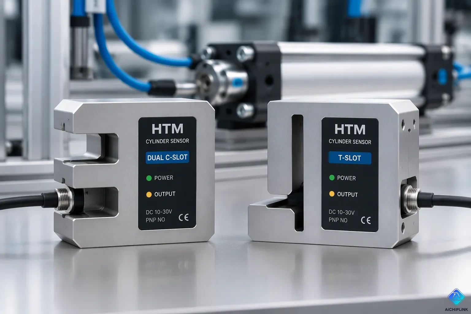
HTM Sensors Dual C-Slot or T-Slot Cylinder Sensors are magnetic position sensors. They detect the piston position inside pneumatic cylinders. These sensors slide into the groove on the cylinder body. There, they read the magnetic field of the piston magnet. The sensor then sends a signal to the control system. The design lets one sensor body fit more than one slot profile.
The sensor family covers compact C-slot bodies and standard T-slot bodies. It also includes adaptor kits for other groove shapes. This post explains the design and the working principle. It also covers the installation steps and the common applications.
Key Takeaways
-
One sensor body works with many cylinder slots when you use adaptor kits. This saves you time and money.
-
Magnetic sensing reads the piston's position through the cylinder wall without touching it.
-
Installing it correctly keeps the sensor firmly in place and the switching point accurate.
-
These sensors give dependable position feedback for automated machines.
-
Make sure the sensor output type matches your PLC input so everything runs smoothly.
HTM Sensors Design and Features
Dual C-Slot and T-Slot Fit
The dual-slot design lets one sensor body fit on more than one cylinder profile. A small C-slot sensor is 15 mm and drops into the groove from above. That top-entry shape works well for small grippers, where space around the cylinder body is tight and side access is poor. The sensor sits low in the slot and leaves the space around it clear.
The wider HTM Sensors mounting family covers T-slot, C-slot, dovetail, and tie-rod cylinders. Adaptor kits connect the gap between profiles. A C-slot sensor with the right adaptor fits a T-slot, and a special adaptor lets it sit in a dovetail groove. This flexibility keeps one sensor model useful across a mixed machine build.
The cylinder slot picks the sensor, not the other way around. Engineers read the groove profile first, then choose the sensor and adaptor that match it. A sensor forced into the wrong slot loses alignment and grip.
Compact Housing and Mounting Options
The small housing keeps the sensor inside the cylinder profile. It does not stick out into the working area, so moving parts and tooling pass without contact. A low profile also protects the sensor from knocks during setup and maintenance.
Mounting hardware varies with the slot type. C-slot bodies accept a direct drop-in fit with a set screw or clamp. T-slot bodies use a slide-in mount that locks along the groove. Adaptor kits add brackets for dovetail and tie-rod cylinders. Each option holds the sensor at a fixed depth, which keeps the sensing gap stable over the stroke.
Builders can mix slot types on one machine and still standardize on a single sensor family. That approach simplifies spare parts and training. The compact housing and the adaptor range together cover most pneumatic cylinder mounts found in automated equipment.
How They Work
Magnetic Sensing Principle
A permanent magnet sits on the piston inside the cylinder. The sensor slides into the slot on the outside of the cylinder wall. The wall separates the two parts, so no contact occurs. The sensor reads the magnetic field through the wall.
Most HTM Sensors models use a Hall-effect element. This element reacts to the strength of the magnetic field. The field grows stronger as the piston magnet moves closer. Field strength drops quickly as the distance grows, so the active zone stays small and well defined. The element converts that change into an electrical signal. A threshold circuit decides when the field is strong enough to count as piston present.
Some models use a reed switch instead. A reed switch holds two thin metal contacts inside a sealed glass tube. The magnetic field pulls the contacts together. The contacts close the circuit and pass current. Reed switches need no supply voltage of their own. Hall-effect sensors need a supply to run their internal circuit.
The cylinder wall material matters. Aluminum and brass do not block the magnetic field. Steel cylinders can weaken it, so the sensor needs a stronger magnet or a closer gap. The sensing gap stays fixed once the sensor locks into the slot. That fixed gap gives repeatable switching at the same piston position on every stroke. A small LED on the sensor body shows the switch state, which speeds up setup.
Output Signals and Switching Behavior
The sensor output feeds a PLC or a valve controller. The output is a discrete signal: on or off. The signal marks one piston position, such as fully extended or fully retracted. Two sensors on one cylinder mark both end positions. Longer strokes may need extra sensors for mid-stroke checks.
Output wiring follows two common conventions. A PNP output switches the positive supply line to the signal wire. An NPN output switches the ground line instead. The PLC input card must match the sensor type. A mismatch leaves the input floating or permanently on.
| Output type | Switches | Typical PLC match |
|---|---|---|
| PNP | Positive line | Sinking input |
| NPN | Ground line | Sourcing input |
Switching behavior adds two more choices. A normally open output stays off until the magnet arrives. A normally closed output stays on and drops out when the magnet arrives. Normally closed wiring suits safety checks, because a broken wire reads the same as a missing piston.
Hysteresis sets a small gap between the switch-on point and the switch-off point. That gap stops the output from chattering when the piston stops near the threshold. The result is one clean pulse per pass, not a burst of false counts. Builders can wire sensors in series for an AND check or in parallel for an OR check. Route sensor cables away from motor and drive cables to avoid false triggers.
Installing on C-Slot and T-Slot Cylinders
C-Slot Drop-In Mounting
A C-slot cylinder takes the sensor straight from above. The installer drops the 15 mm sensor body into the groove. The body sits low in the slot and stays inside the cylinder profile. This top-entry method suits small grippers, where the sides of the cylinder sit close to other parts.
The steps follow a fixed order:
-
Clean the groove and remove metal chips or grease.
-
Slide the sensor to the target piston position.
-
Push the body down until it seats flat in the slot.
-
Tighten the set screw or clamp until the body cannot move.
-
Power the cylinder and check the LED at each end position.
A loose sensor shifts along the groove during the stroke. The switching point then drifts, and the PLC reads the piston at the wrong place. The installer should test the grip by hand before running the machine. A firm push along the slot should not move the body.
Cable routing matters at this stage. The cable should leave the slot without a sharp bend. A tight bend stresses the conductor and shortens sensor life. Tie the cable to the machine frame at short intervals, away from moving tooling.
T-Slot Mounting and Adaptors
A T-slot cylinder holds the sensor with a slide-in mount. The mount locks along the groove and fixes the sensing depth. The installer slides the sensor and mount into the slot from the open end. A quarter-turn or a set screw then locks the assembly in place.
Adaptor kits extend the same sensor family to other groove shapes. A C-slot sensor with the correct adaptor fits a T-slot body. A special adaptor lets the sensor sit in a dovetail groove. Tie-rod cylinders use their own bracket, which clamps to the rod and holds the sensor at the right gap.
The adaptor must match the groove profile exactly. A poor match tilts the sensor and changes the gap to the piston magnet. The field strength drops with distance, so a tilted body may miss the piston or switch late. The installer should confirm the sensor sits square in the slot before tightening.
Mixed machine builds benefit from this range. One sensor model plus a few adaptor kits covers C-slot, T-slot, dovetail, and tie-rod cylinders. Spare parts stay simple, and technicians learn one mounting method. The cylinder slot still decides the choice. The installer reads the groove first, then picks the sensor and adaptor that fit it.
Applications and Benefits
Typical Automation Use Cases
Pneumatic cylinders power many automated jobs. Pick-and-place units, clamping fixtures, and ejector slides all depend on piston position feedback. A sensor at each end position tells the PLC when the stroke finishes. Then the machine starts the next step without delay or guesswork.
Small grippers gain the most from the compact C-slot body. The 15 mm sensor drops in from above and stays inside the profile. Tooling passes over the cylinder without touching it. Assembly cells, packaging lines, and test stands use this setup to confirm a gripper has closed on a part.
Longer strokes need mid-position checks. A sensor placed along the slot marks a partial extension or a home position. Sorting machines and indexing tables use these signals to time their motion. Two end sensors plus one mid-stroke sensor give a simple three-state readout.
Safety-related circuits also use these sensors. A normally closed output drops out when the piston leaves its rest position. A broken wire reads the same as a missing piston, so the fault shows up right away. This behavior suits guard doors and locking pins.
Advantages and Fit Versus Other Sensors
The dual-slot design cuts the number of part numbers a plant must stock. One sensor body plus adaptor kits covers C-slot, T-slot, dovetail, and tie-rod cylinders. Technicians learn one mounting method and one wiring scheme. Spare parts stay simple across a mixed machine build.
Hall-effect models suit most general automation work. They need a supply voltage and give a clean, repeatable switching point. Reed switch models fit where no supply is available at the sensor. Each type has a place, and the cylinder slot and control input decide the match.
HTM Sensors models fit builds that mix cylinder brands and groove shapes. The adaptor range keeps the sensing gap stable across profiles. A builder reads the groove first, then picks the sensor and adaptor that match it. That order keeps alignment correct and switching repeatable.
How to Select the Right Sensor
Matching Slot Type and Stroke
The cylinder groove is the first thing to check. A C-slot body takes the small drop-in sensor. A T-slot body takes the slide-in mount. Dovetail and tie-rod cylinders need their own adaptor kit. The buyer reads the groove profile before looking at any other spec. HTM Sensors adaptor kits then connect the gap between profiles.
Stroke length changes how many sensors you need. Short strokes need one sensor at each end position. Long strokes may need a mid-stroke sensor to check a home or partial-extension position. The installer should make sure the sensor cable reaches the control cabinet along the full travel. A cable that runs tight at full extension will fail early.
Electrical and Environmental Ratings
The PLC input card decides the output type. A sinking input card works with a PNP sensor. A sourcing input card works with an NPN sensor. The buyer should check the supply voltage range against the machine's control voltage. A mismatch in either area leaves the input floating or stuck on.
The IP rating sets where the sensor can be used. Washdown cells and machining centers with lots of coolant need a sealed body. Dry assembly cells can use a standard housing. Hazardous-area installations need models rated for that environment, and the buyer should confirm the rating before ordering.
Reed and Hall-effect models each fit different jobs. Reed switches need no supply voltage, so they work in simple circuits with no power at the sensor. Hall-effect models give a clean, repeatable switching point and fit most general automation work. Neither type is better than the other; the circuit and the environment decide the match.
HTM Sensors Dual C-Slot or T-Slot Cylinder Sensors are magnetic position sensors. They read where the piston is through the cylinder wall. The dual-slot design pairs one sensor body with adaptor kits. So one family covers C-slot, T-slot, dovetail, and tie-rod cylinders. Magnetic sensing turns the piston magnet's position into a clear PNP or NPN output signal for the PLC. Drop-in mounting keeps installation simple on both slot profiles. C-slot bodies use top entry, and T-slot bodies use a slide-in mount. The cylinder groove still decides the choice. Read the slot first, then match the sensor and adaptor to it.

Written by Jack Elliott from AIChipLink.
AIChipLink, one of the fastest-growing global independent electronic components distributors in the world, offers millions of products from thousands of manufacturers, and many of our in-stock parts is available to ship same day.
We mainly source and distribute integrated circuit (IC) products of brands such as Broadcom, Microchip, Texas Instruments, Infineon, NXP, Analog Devices, Qualcomm, Intel, etc., which are widely used in communication & network, telecom, industrial control, new energy and automotive electronics.
Empowered by AI, Linked to the Future. Get started on AIChipLink and submit your RFQ online today!
Frequently Asked Questions
Can one sensor fit both a C-slot and a T-slot cylinder?
Not by itself. The sensor body matches one groove profile. An adaptor kit bridges the gap between profiles. A C-slot sensor with the correct adaptor fits a T-slot body. The installer reads the groove first, then picks the sensor and adaptor that match it.
Do these sensors need a power supply?
It depends on the sensing element. Hall-effect models need a supply voltage to run their internal circuit. Reed switch models need no supply of their own. The control circuit and the available power at the sensor decide which type fits the job.
How many sensors does a cylinder need?
Most cylinders use one sensor at each end position. That setup marks fully extended and fully retracted. Long strokes may need a mid-stroke sensor to check a home or partial-extension position. The stroke length and the control sequence set the count.
What happens if the sensor sits loose in the slot?
A loose sensor shifts along the groove during the stroke. The switching point then drifts, and the PLC reads the piston at the wrong place. The installer should test the grip by hand. A firm push along the slot should not move the body.
Can these sensors work on steel cylinders?
Steel cylinder walls can weaken the magnetic field. The sensor then needs a stronger piston magnet or a closer gap. Aluminum and brass walls do not block the field. The buyer should confirm the wall material before ordering.