EFuse Capacitive Load Startup: Calculate Inrush Current and Prevent Hiccup Trips
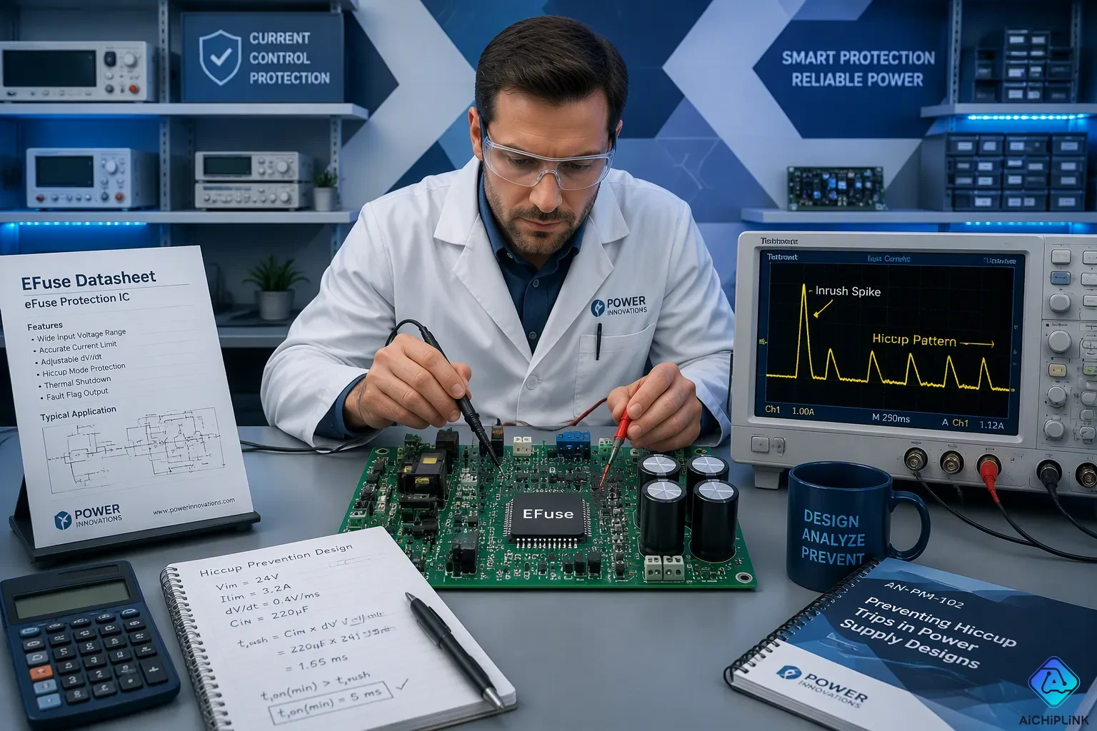
You calculate inrush current with a simple formula: I_inrush = C_load × dV/dt. Here, C_load is load capacitance in farads, and dV/dt is the output voltage ramp rate in volts per second. A second estimate, I = V / R, divides input voltage by total series resistance. This works well when the capacitor starts uncharged. A discharged capacitor acts like a short circuit at first. Its current can be much higher than steady-state current.
Your efuse avoids a hiccup trip when peak inrush current stays below the overcurrent threshold. The internal FET must also stay inside its safe operating area (SOA). This guide walks you through three steps: calculate worst-case inrush current, compare it against the efuse limits, then apply soft-start or load-cap techniques. Good protection design starts with these numbers.
Key Takeaways
-
Use the formula I = C × dV/dt to find the peak inrush current for a linear ramp.
-
Compare the highest startup current to the eFuse overcurrent limit and fault timer.
-
Use a dV/dT capacitor to make the output voltage rise more slowly, which lowers the peak current.
-
Check that the eFuse safe operating area can handle the startup energy.
Capacitive Load Startup and Inrush Basics
Why Capacitors Draw High Startup Current
When you first turn on power to a capacitive load, the capacitor does not act like it does during normal use. At the moment of connection, the capacitor voltage is zero. A discharged capacitor acts like a short circuit. The full source voltage appears across the total series resistance in the charging path. This sets the highest instant current you will see.
The formula for this peak is simple: I_peak = V / R. V is the input voltage. R includes the capacitor's ESR, trace resistance, and any limiting resistor you add. At time t = 0.0 seconds, the current through the resistor equals the source voltage divided by the total resistance. As time passes, the current drops toward zero as the capacitor charges. This behavior shows that initial current depends only on resistance. If resistance is very small, the predicted current becomes very high. The ideal RC model fails with negligible resistance.
This huge current surge can be many times the capacitor's steady-state charging current. Engineers call this a capacitive load startup event. Controlling this startup inrush is key for reliable efuse operation. Calculating the peak inrush current helps you find out if your efuse can handle the surge.
Load Capacitance, ESR, and Slew Rate Effects
Three things control the peak and duration of the inrush: load capacitance, capacitor ESR, and the output slew rate of your power source or efuse.
Larger capacitance needs more charge to reach the operating voltage. More charge means higher total energy delivered during startup. The inrush current must supply this charge, so its size and duration grow with capacitance value.
ESR gives some natural current limiting. Typical ceramic capacitors have ESR in the milliohm range. Electrolytic capacitors have higher ESR, often tens to hundreds of milliohms. This resistance helps lower the peak inrush. However, it also causes a voltage drop across the capacitor during the charging event. The drop appears across the capacitor's internal resistance.
The output slew rate, dV/dt, directly controls inrush current using the formula I = C x dV/dt. Slower slew rates lower peak current. Faster slew rates raise it. The inrush duration follows the RC time constant of the charging path. This duration usually falls between a few milliseconds and several hundred milliseconds for practical circuits. You can use this knowledge to expect the duration for a capacitive startup load.
Understanding these effects lets you predict inrush behavior before picking components. The next section shows you how to calculate exact values.
How to Calculate Inrush Current
Using I = C × dV/dt
The main formula for inrush current is I = C × dV/dt. In this formula, I is the peak inrush current in amperes. C is the load capacitance in farads, and dV/dt is the output voltage ramp rate in volts per second. This equation shows how much current the capacitor needs to charge at a certain rate. A faster ramp needs more current, while a slower ramp needs less.
Imagine your efuse ramps its output at 1 V per millisecond, which is 1000 V per second. Your load capacitance is 100 microfarads, or 0.0001 farads. Multiply 0.0001 F by 1000 V/s. The answer is 0.1 A, or 100 mA. That number is your peak inrush current for that ramp rate. You can figure out inrush current this way for any mix of capacitance and slew rate. The formula assumes the capacitor starts fully discharged and the ramp is linear.
Worst-Case Load Calculation With I = V / R
The second estimate treats the uncharged capacitor as a short circuit. At the very first moment, the full input voltage appears across the total series resistance. That resistance includes capacitor ESR, trace resistance, connector resistance, and any limiting resistor. The peak current is I = V / R. This estimate gives the absolute worst case, because real capacitors charge up and the current drops fast.
Run a worst-case load calculation with maximum input voltage and minimum ramp time. Take a 12 V input, a 100 microfarad load, and a 1 millisecond ramp. The dV/dt method gives 1.2 A. Now add a total series resistance of 0.5 ohms. The I = V / R estimate gives 24 A. The real peak falls between these values, closer to the resistive estimate at t = 0. The voltage drop across that series resistance also lowers the voltage the capacitor finally reaches, so check it against your load's minimum operating voltage.
Energy stored in the capacitor follows E = 0.5 × C × V². For 100 microfarads at 12 V, that is 0.5 × 0.0001 × 144, or 7.2 millijoules. The efuse's internal FET must absorb or pass this energy without leaving its safe operating area.
For thermal and RMS analysis, integrate the square of the current over the inrush duration, then take the square root. This RMS value matters when the inrush lasts long enough to heat the FET. You can calculate inrush current as a peak for threshold checks and as an RMS value for thermal checks. Both views help your design pass without nuisance trips.
EFuse Hiccup Trip Behavior Explained
Trip, Cool-Down, and Retry Cycle
An efuse goes into hiccup mode when it senses too much current. The device turns off its internal FET, waits to cool down, and then tries to start again. If the problem is still there, this cycle keeps repeating. You will notice short output pulses with long off periods in between. The efuse never sends full power to your load.
This action keeps the internal FET from getting too hot. A lasting short circuit or a heavy capacitive load keeps the current high. The efuse cannot tell a real fault apart from a slow-charging capacitor bank. It only knows the current went past the threshold for too long. Your startup inrush looks like a fault to the device.
Fast Trip Threshold vs. Overcurrent Threshold
An efuse often has two current thresholds. The overcurrent threshold sets the level for normal current limiting. The fast trip threshold is higher and reacts much faster. A short inrush spike can cross the fast trip threshold even when the average current is fine. The efuse sees that spike and shuts down right away.
This is why high inrush current causes hiccup trips. The fault timer starts when current goes past the limit. Your capacitor needs time to charge. If the timer runs out before the capacitor finishes charging, the efuse calls it a fault. The output voltage across the load never reaches its target. The efuse retries, sees the same inrush, and trips again.
You can stop this cycle with proper protection design. Set the fault timer longer than the expected inrush duration. Pick an efuse with a fast trip threshold above your worst-case peak current. These steps keep the efuse working normally during startup.
Design Techniques to Prevent Hiccup Trips
Soft-Start, dV/dT Pins, and Ramp Capacitors
The simplest way to avoid hiccup trips is to make the output voltage rise slowly. Many eFuse parts have a dV/dT pin. You put a capacitor from that pin to ground. The eFuse uses a tiny internal current to charge that capacitor. The output then goes up in a smooth ramp, not a sudden jump. A slower ramp lowers the peak inrush current. This keeps the eFuse below its trip limit.
You can find the ramp capacitor value from the capacitor equation. The basic formula is i(t) = C * dv/dt. You can change it to C = i / (dv/dt). For a steady current, the voltage change over time is ΔV = I * Δt / C. For example, a 100 µF capacitor with 10 mA charging current gives a ramp rate of 100 V/s. You can use this same formula to choose your dV/dT capacitor. A bigger ramp capacitor makes the rise slower and the peak current smaller.
The basic capacitor formula is i(t) = C * dv/dt. It can be rearranged to C = i / (dv/dt). For a steady current, the voltage change over time is ΔV = I * Δt / C. For example, a 100 µF capacitor with 10 mA charging current gives a ramp rate of 100 V/s.
Current Limits, Blanking Time, and Pre-Charge Circuits
Your eFuse protection plan also uses two timing numbers. The current limit sets the highest current the device will let through. The fault timer, also called blanking time, sets how long the device puts up with that current before it trips. Set the blanking time to be longer than your expected inrush time. This lets the load capacitor charge up without a wrong fault. A longer blanking time gives more safety, but it also makes the response slower to a real short circuit.
There are other options when soft-start by itself is not enough. A pre-charge circuit uses a small resistor or a MOSFET to partly charge the load capacitor before the main path turns on. A resistor or inductor in series limits the first current. An NTC thermistor starts with high resistance and then drops as it heats up. Holding a MOSFET in its linear region keeps the device safe during the ramp.
Each choice has trade-offs. A series resistor makes a constant voltage drop and wastes power. This hurts efficiency and may break your supply rating. A higher current limit lowers the voltage drop but might push the inside FET out of its safe operating area. Your design must balance these things. Check the SOA curve for every eFuse you think of using. Make sure the part can take the startup energy without harm. A careful design review now saves you from problems in the field later.
Practical EFuse Load Calculation Example
Selecting an EFuse for a 100 µF Load
You have a 12 V power line, a 100 µF load capacitor, and you want to ramp up in 1 ms. Your inrush current is 1.2 A using the formula I = C × dV/dt. Now you need an efuse that can handle this start-up without turning off. Start by checking the efuse's overcurrent limit. It must be above 1.2 A and have some extra room. The fast trip limit must also be above this peak. A part with a 2 A overcurrent limit and a 3 A fast trip gives you a safe margin.
Next, pick the dV/dT capacitor. A bigger ramp capacitor makes the output rise slower and lowers the peak current. A smaller one makes it faster and raises the current. Pick a value that keeps the ramp close to your 1 ms goal. Then choose the current-limit resistor. This resistor sets the highest current the efuse allows. Make sure the voltage drop across it is small enough that your load still gets its minimum needed voltage.
Verifying Margins Against SOA and Fault Timer
The safe operating area (SOA) of the MOSFET sets the allowed mix of voltage, current, and time under stress. A protection that works for the wire can still break the efuse switch if the product of drain-to-source voltage and drain current lasts too long. Using I²t alone is not safe for inrush. You must also follow the SOA boundary. The rule to coordinate is: load envelope < protection curve < wire and connector damage curve.
Make sure the fault timer is longer than your inrush time. If the timer runs out first, the efuse will hiccup. During startup, use soft-start, slew-rate control, current limiting, or capacitive-load modes to power the load without false trips. At the same time, keep the switch inside its SOA. Run this check for every efuse you look at. A careful design review now saves your supply and your board.
Follow this three-step workflow for every capacitive load you design. First, calculate worst-case inrush using I = C x dV/dt. Second, compare that result against your efuse overcurrent threshold and SOA limits. Third, implement soft-start or reduce load capacitance if margins look tight. Hiccup trips always signal insufficient startup margin, not a random fault. Use this checklist on your next board revision:
-
Verify the inrush peak stays below the supply rating
-
Set the blanking timer longer than the expected charge duration
-
Check the protection curves against the full load envelope
-
Review voltage drop across any series resistor for efficiency
Good design prevents hiccup trips at power-on.

Written by Jack Elliott from AIChipLink.
AIChipLink, one of the fastest-growing global independent electronic components distributors in the world, offers millions of products from thousands of manufacturers, and many of our in-stock parts is available to ship same day.
We mainly source and distribute integrated circuit (IC) products of brands such as Broadcom, Microchip, Texas Instruments, Infineon, NXP, Analog Devices, Qualcomm, Intel, etc., which are widely used in communication & network, telecom, industrial control, new energy and automotive electronics.
Empowered by AI, Linked to the Future. Get started on AIChipLink and submit your RFQ online today!
Frequently Asked Questions
How do I know if my efuse will trip during startup?
Compare your peak inrush current against the efuse overcurrent threshold. Use I = C × dV/dt for a linear ramp. If the peak stays below the limit and the fault timer outlasts the charge time, your efuse should start cleanly.
What causes an efuse to enter hiccup mode?
The fault timer expires before your capacitor finishes charging. The efuse sees high current, shuts off, cools down, and retries. Each retry hits the same inrush, so the cycle repeats. An efuse cannot distinguish a slow-charging capacitor from a real fault.
Can I just pick a higher current limit to avoid trips?
A higher limit helps, but it pushes the internal FET closer to its safe operating area boundary. Check the SOA curve for your worst-case voltage and current. If the FET cannot absorb the startup energy, choose soft-start instead.
How does a dV/dT capacitor prevent hiccup trips?
The dV/dT capacitor slows the output ramp. A slower ramp lowers peak inrush current through I = C × dV/dt. This keeps the efuse below its trip threshold. Pick the capacitor value so the ramp matches your target startup time.
What is the fastest fix for a nuisance trip?
Add or increase the soft-start capacitor first. This lowers peak current without wasting steady-state power. If that fails, reduce load capacitance or add a pre-charge path. Always verify the efuse stays inside its SOA during the new ramp.