What Modbus Relay and I/O Modules Are and How They Work Together
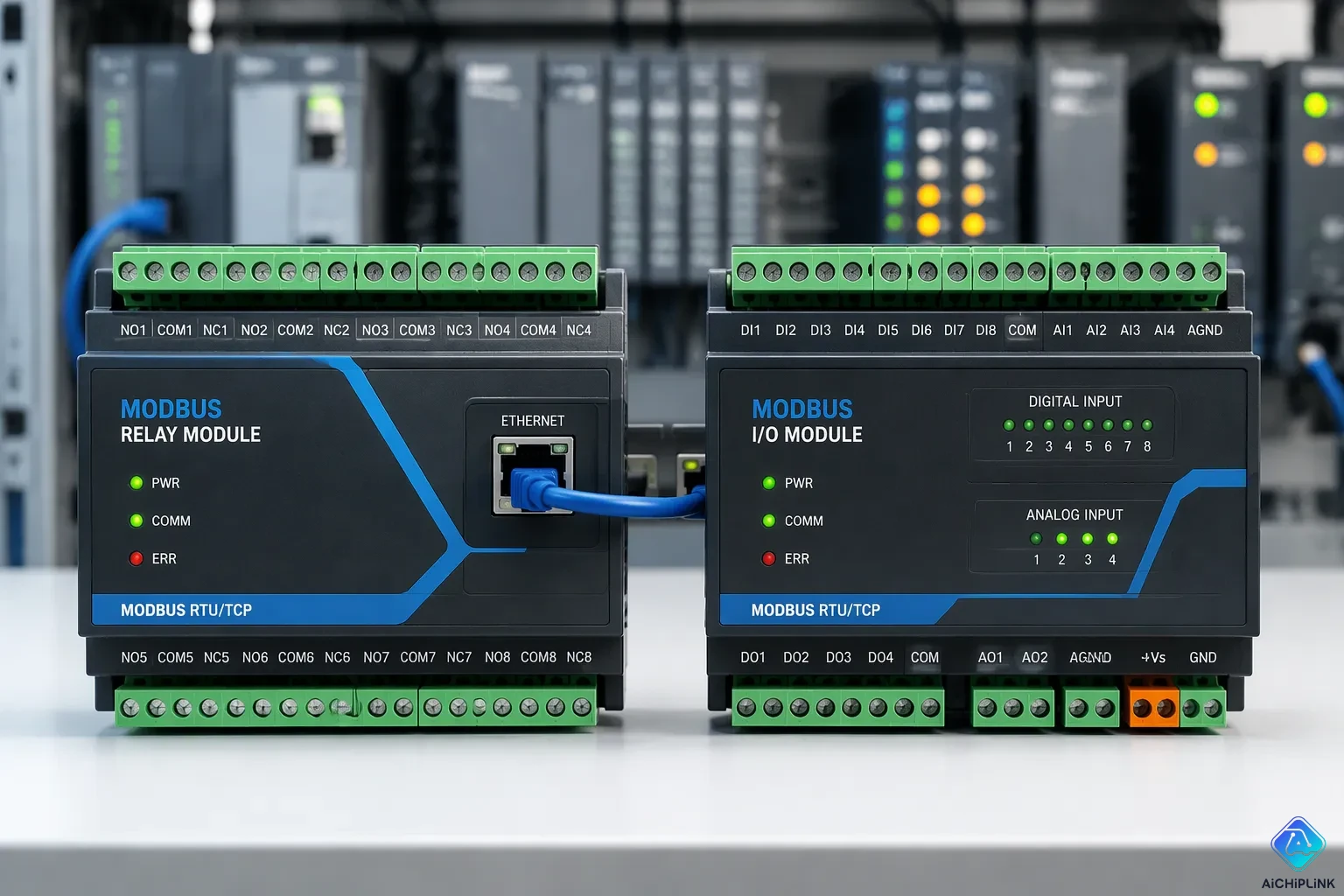
A Modbus relay module is a relay board that has a Modbus interface. It lets a controller switch loads from a distance over a network. A Modbus I/O module reads field inputs and drives outputs using the same protocol. Field inputs include switches, sensors, and status contacts.
Both devices share one Modbus network. The relay module handles switching for higher power. The I/O module handles sensing and signal-level outputs. A master coordinates the two by giving each device an address on the bus. The relay contacts carry the load current. The logic side of the module stays on the network. Each unit then does the job it fits best.
Key Takeaways
-
A Modbus relay module turns high-power loads on and off over a network. A Modbus I/O module reads sensors and controls signals. Both of them use the same Modbus network.
-
Every device on the network needs its own address. You set the address and baud rate with DIP switches. Match the baud rate on every device so communication does not fail.
-
Relay modules take care of switching. I/O modules take care of sensing. A master controller runs both on the same bus. This split keeps wiring simple and cuts down on cable runs.
-
Pick fixed-function boards when your point counts stay the same. Pick configurable modules when your needs may change. Check the protocol (Modbus or BACnet) before you order.
-
Wire things the right way: ground shielded cables at one end, keep signal cables away from power cables, and use twisted pairs for analog signals. These steps stop noise and drift.
Modbus Relay Modules
What a Modbus Relay Module Is
A Modbus relay module is a board that holds one or more electromechanical relays and hooks up to a Modbus network. Each relay works as a remote switch. A Modbus controller sends a command, and the board closes or opens the contact. The contact then carries the load current for a pump, a light, a valve, a fan, or a contactor coil.
The module keeps its logic side on the bus and its power side on the load. This split lets a low-voltage network command a high-power circuit. Channel counts differ by design. The DIUSTOU wiki documents a USB Modbus Relay PRO V2 that supports up to 64 channels, with control registers for channels 1 through 64. The Waveshare wiki describes an industrial 8-channel relay module on an RS-485 bus with 8-channel digital input. Buyers pick a channel count that matches the number of loads they need to switch.
Modbus Relay Control in Practice
Modbus relay control follows a clear command path. The Modbus controller or I/O module gets a command over the network. It then sets a physical output, and that output drives the relay coil. The coil energizes, the contact moves, and the load switches. A master can use a write single coil command to change one relay state, or read coils to check the current state.
The Modbus register map defines where each channel lives. A holding registers layout often groups channel controls in order, so the register map stays predictable across devices. A Modbus network relay with this structure is easy to address and easy to troubleshoot. Typical form factors include DIN-rail blocks, board-level modules, and enclosed units. Small boards may offer a few channels, while larger units reach the 64-channel range noted by DIUSTOU. Modbus RTU over RS-485 remains a common transport for these boards in industrial cabinets.
Modbus I/O Modules
Input and Output Types
A Modbus I/O module works like the remote hands of an automation system. It lets a controller reach out to field devices. It turns network commands into electrical outputs and field signals into network data. The register map shows the master where each point is located. That way, the master can read holding or input registers to gather field values.
Input variety covers several signal families. CControl describes universal inputs that handle temperature, analog, resistance and binary signals in a single module. Discrete inputs accept contact closure and retentive pulse counting at 100 Hz. An accumulator works as a high-speed counter that keeps its value through a power failure. Multi-input designs also exist, such as six RTD inputs for high-accuracy temperature sensing. Outputs include relay contacts and analog signals such as 0 to 10 VDC at 20 mA.
Combined modules pair inputs and outputs on one board. Avyanna Tech lists an 8-input, 8-relay-output unit with sinking digital inputs at 5000 Vrms isolation and relay outputs rated 5A at 250 VAC or 30 VDC. A smaller example is four digital inputs and two relay outputs for local switching, such as receiving signals from light switches. Each Modbus I/O point stays addressable through the register map.
Configurable I/O Modules for BACnet and Modbus
Configurable I/O modules for BACnet and Modbus support multiple protocols and flexible point setup. Tyrrell Products notes that BACnet came from ASHRAE in 1995 and serves building automation, while Modbus came from Modicon in 1979 and serves industrial control. BACnet devices describe themselves and support discovery, change of value, alarms, schedules and trend logs. Modbus uses four tables of coils and registers with no metadata, and the master must poll.
Configurable I/O modules fit either world. Choose BACnet when a project needs alarms, scheduling, trends and equipment control. Choose Modbus when simple, reliable reading or writing of equipment data is enough. Many configurable I/O products run Modbus RTU over RS-485, and some add BACnet MS/TP on the same RS-485 wiring. A team planning Modbus or BACnet operation should confirm which protocol the head-end expects before ordering.
How They Work Together
Shared Modbus RTU Network
A Modbus RTU network over RS-485 lets both device types speak the same language. RS-485 is a differential standard with strong noise immunity, so it works well for long cable runs in industrial settings. The RS-485 bus supports up to 32 unit loads per segment and reaches 1200 meters at 9600 baud with proper termination, according to Industrial Monitor Direct. Repeaters add more segments when a site needs more nodes.
Each device on the bus needs its own unique address. DIP switches set the device address and baud rate on most modules. The Modbus RTU address range runs from 1 to 247, and address 0 stays reserved for broadcast. Baud rate must match on every node. MachineCDN notes that a mismatch in any serial parameter stops communication completely. Cable length also limits speed. The chart below from MachineCDN shows how maximum reliable distance drops as baud rate goes up.

LED indicators help with troubleshooting. A rapid flicker means healthy two-way traffic. A slow, distinct flash points to slow or garbled responses, often from a weak power supply. No flash at all suggests a wiring break, a wrong baud rate, or no power. These patterns let a technician trace a fault on the Modbus RTU network without a protocol analyzer.
Complementary Roles in a Control System
The division of labor is simple. I/O modules sense field conditions and signal the results. Relay modules switch the loads. A Modbus controller coordinates both on one bus. The master polls input registers and holding registers, then issues a write single coil command to change a relay state. A technician can also read coils to confirm the current output state. The register map keeps coil and register addresses predictable across devices.
Consider a packaging line. A physical cycle start button sits at the machine. A relay wired to a remote I/O block can bypass that button when the line runs in automatic mode. The Modbus controller or I/O module receives the command, sets its output, and the relay contact closes across the button terminals. The line starts without an operator at the panel.
Network I/O relay modules with Modbus sensor ports add another layer. These ports support temperature and humidity sensors, per Axis. One module then handles local switching and environmental sensing. The Modbus network relay and the I/O module share the same RS-485 bus, so wiring stays simple. Each Modbus I/O point remains addressable through the register map. This setup keeps relay control and sensing close to the field device and cuts the cable runs back to the cabinet.
Practical Considerations
Performance, Fit, and Compliance
Channel count, input accuracy, and switching ratings decide where a module fits. A module with 16-bit analog resolution fits temperature and pressure work. One least significant bit equals 153 µV across a 10 V span, per Industrial Monitor Direct. Differential inputs reject common-mode noise on long cable runs. Single-ended inputs work for runs under 50 m. Industrial control favors rugged switching ratings. Modbus-based building systems favor accurate analog sensing. A controller or I/O module reads the register map to find each point. An analog output drives a valve positioner, and a relay output switches a small load.
Wiring practice protects that performance. Industrial Monitor Direct lists four rules:
-
Ground the drain wire of shielded twisted pair at the panel end only.
-
Bond the 24 VDC return to chassis ground at the power supply, not at every node.
-
Keep analog signal cables at least 150 mm away from relay and power cables.
-
Use twisted pair for 4–20 mA loops and share one panel supply with the I/O module.
A ground loop shows up as a 4–20 mA reading that drifts by 0.5–2 mA when a motor starts. A signal isolator in the loop fixes it.
Cost and Integration Factors
Compliance depends on the site. A Modbus RTU network in a plant follows industrial wiring rules. A project in a building may need BACnet support. Configurable I/O modules for BACnet and Modbus cut the number of part types a team stocks. Confirm the protocol before ordering.
Cost tracks module count, wiring, and scalability. Each added node needs cable, a unique address, and panel space. Modular RTU blocks scale in small steps, so a team buys only the points it needs. A Modbus controller polls input registers and the register map of each device. A clean layout cuts commissioning time. A second Modbus controller on the same RS-485 bus can share the load. RS-485 wiring stays short when nodes sit near their loads, and one RS-485 segment serves many points. Configurable I/O modules add flexibility at a higher unit cost. Configurable I/O also lets a team change a point type in the field. Fixed-function boards cost less per point. Neither option wins outright; the fit depends on point count, protocol, and budget.
A Modbus relay module is a relay board with a Modbus interface that switches things from far away. A Modbus I/O module reads field inputs and runs field devices on the same network.
The split of work stays simple. Relays do the switching, input and output modules do the sensing and signaling, and Modbus ties both together on one bus. Each device keeps its own address on the bus. A team should pick the module that fits the job. Count the loads that need switching and the points that need sensing. Then weigh cost against growth. Fixed-function boards work well when point counts stay the same, while configurable modules fit sites that change. That balance keeps relay control easy and the network running smoothly.

Written by Jack Elliott from AIChipLink.
AIChipLink, one of the fastest-growing global independent electronic components distributors in the world, offers millions of products from thousands of manufacturers, and many of our in-stock parts is available to ship same day.
We mainly source and distribute integrated circuit (IC) products of brands such as Broadcom, Microchip, Texas Instruments, Infineon, NXP, Analog Devices, Qualcomm, Intel, etc., which are widely used in communication & network, telecom, industrial control, new energy and automotive electronics.
Empowered by AI, Linked to the Future. Get started on AIChipLink and submit your RFQ online today!
Frequently Asked Questions
How does a device get its address on a Modbus RTU network?
DIP switches set the device address and baud rate on the RS-485 wiring. The address range runs from 1 to 247, and address 0 stays reserved for broadcast. Every node must match the baud rate. A mismatch stops communication completely.
When should a team choose BACnet over Modbus?
BACnet fits projects that need alarms, scheduling, trends, and equipment control. Modbus fits simple, reliable reading or writing of equipment data. Configurable I/O modules for BACnet and Modbus let one product serve either world. Confirm the protocol the head-end expects before ordering.
What causes communication failures on the bus?
A baud rate mismatch, a wiring break, or a weak power supply can stop traffic. LED indicators help. A rapid flicker means healthy two-way traffic. A slow flash points to garbled responses. No flash suggests a wiring break or no power. Check the Modbus RTU settings and the RS-485 bus.
How does a master find each point on a module?
The register map shows where each point lives. A Modbus controller reads holding or input registers to gather field values. It writes a single coil to change a relay state. A technician can read coils to confirm the current output state.
How do relay and I/O modules split the work?
Relay modules switch loads. I/O modules sense field conditions and signal the results. One master coordinates both on a shared RS-485 link. A team can add configurable I/O modules as points grow. This setup keeps wiring simple and cuts cable runs.