What is a Digital Potentiometer?
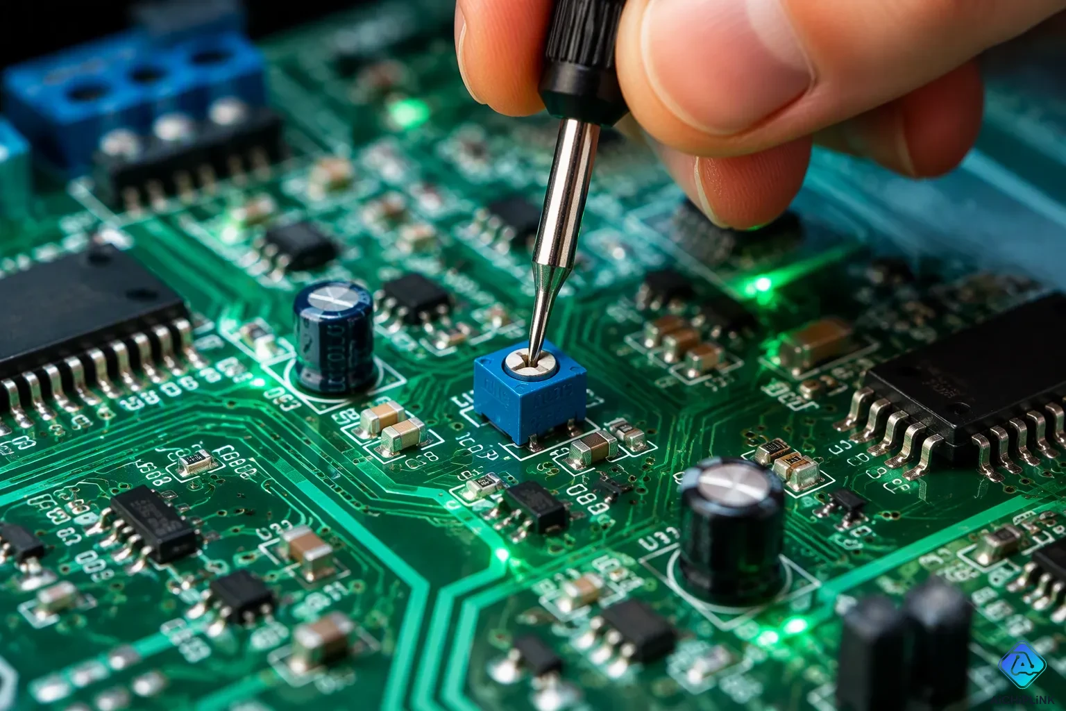
A digital potentiometer is a three-terminal device that changes resistance using digital signals. You control it with a microcontroller instead of your hand. Two fixed end terminals set the total resistance range. A wiper terminal moves along that range to choose the output value.
Think of this potentiometer as a volume knob you can turn electronically. Your microcontroller sends commands, and the wiper responds right away. This design avoids mechanical wear and allows exact, repeatable changes. You can adjust resistance thousands of times without touching it.
This device is also called a resistive digital-to-analog converter. It connects digital control with analog circuits, letting you use software to manage real-world signals.
Key Takeaways
-
A digital potentiometer changes resistance using digital signals, not by hand.
-
It uses a resistor ladder and switches to set resistance exactly.
-
Digital potentiometers are accurate, long-lasting, and can be controlled by software.
-
They have certain limits, such as cost, step resolution, and current.
-
Pick the correct resistance range and interface for your project.
What is a Digital Potentiometer?
A digital potentiometer is a three-terminal device that changes resistance using digital signals. You control it with a microcontroller instead of your hand. Two fixed end terminals set the total resistance range. A wiper terminal moves along that range to choose the output value.
Think of this potentiometer as a volume knob you can turn electronically. Your microcontroller sends commands, and the wiper responds right away. This design avoids mechanical wear and allows exact, repeatable changes. You can adjust resistance thousands of times without touching it.
This device is also called a resistive digital-to-analog converter. It connects digital control with analog circuits, letting you use software to manage real-world signals.
Definition and Three-Terminal Structure
A digital potentiometer works as a part controlled by digital signals, and it has three terminals. The two end terminals connect to the fixed resistance part. The wiper terminal moves along that part to pick different resistance values. This setup looks like a regular analog potentiometer, but the key difference is that digital signals move the wiper, not a physical knob.
Having three terminals gives you options when building circuits. You can use the digital potentiometer as a variable resistor by hooking up only one end terminal and the wiper. Or, you can use it as a voltage divider by connecting all three terminals. This flexibility makes the part useful in many different situations.
Each digital potentiometer has a resistor ladder built into its chip. The ladder is a chain of resistors linked one after another. Each spot where two resistors meet is a tap point. The wiper position matches one of these taps, chosen by a digital address. The digital code you send decides which tap connects to the wiper, which then sets the resistance value.
How It Works: Resistor Ladder and Switches
The resistor ladder is the main part of the digital potentiometer. Each step on the ladder has its own switch. When you send a digital command, the device turns on the switch at the chosen step. This action connects that step to the output terminal. The chosen step sets the resistance ratio, turning a digital input into a matching analog resistance value.
The number of steps depends on the bit resolution of the device. An 8-bit digital potentiometer gives you 256 steps. Common resolutions range from 5 to 10 bits, giving you 32 to 1024 steps. More steps mean finer control over resistance changes. You can pick the resolution that fits your project's precision needs.
You control the wiper position through different programming interfaces. The I2C interface uses two signals: SCL for clock and SDA for two-way data. It supports standard and fast modes up to 400 kHz clock rate. The SPI interface uses four signals: CS for chip select, SCK for clock, SDI for slave input, and SDO for slave output. It runs up to 50 MHz clock rate. A push-button interface lets you add two switches for simple control without a host controller. An up/down interface works with a host controller, simple logic, or a rotary knob using increase and decrease signals.
Each interface type fits different needs. I2C works well when you have few pins available. SPI offers faster communication for quick adjustments. Push-button control suits standalone setups where you want manual control. The up/down interface gives you flexibility for various control methods. Your choice depends on your system design and speed needs.
The digital potentiometer connects digital control with analog circuits. You get precise, repeatable resistance changes without moving parts. This reliability makes the part great for calibration, audio control, and filter tuning in modern electronics.
Digital Potentiometer vs. Analog Potentiometer
When you compare a digital potentiometer to a traditional mechanical one, you see two very different ways to do the same job. Both devices adjust resistance in a circuit. But they do it in completely different ways. A mechanical potentiometer relies on physical contact between a wiper and a resistive track. A digital potentiometer uses electronic switches and a resistor ladder. This basic difference creates clear benefits and some real trade-offs.
Advantages of Digital Potentiometers
Digital potentiometers offer several benefits that make them appealing for modern designs:
-
Increased accuracy: You can set a digital potentiometer very precisely. This accuracy gives you extremely fine control over your electronic system.
-
Increased flexibility: You can set up these devices for many control options. Complex systems benefit from this adaptability.
-
Increased durability: Mechanical parts wear out over time. Digital versions have no moving parts, so they do not wear down with use.
-
Precise control: You can program a digital potentiometer to hit exact resistance values. This ability allows exact tuning and calibration.
-
Wide range of values: You can find parts from 0-100 ohms to 10K ohms or more. This range gives you flexibility in choosing parts.
-
Ease of use: You can program and adjust these devices easily. DIY projects and quick changes become simple tasks.
-
Software control: You can adjust resistance from afar through software. Industrial applications benefit from automated control.
-
Improved stability: These parts resist temperature changes and outside factors. Your system stays stable under changing conditions.
-
Simplified design: You can swap mechanical potentiometers for digital ones. This change reduces part count and improves reliability.
-
Smaller size: Digital potentiometers take up much less space. You can fit more parts into your design.
-
On-the-fly adjustability: You can change resistance without swapping parts. Rapid prototyping and testing become much faster.
These advantages make the digital potentiometer a powerful tool. You get repeatable results every time. You can store settings in memory. You can adjust values from a distance. All these features come from simple digital commands.
Limitations and Trade-offs
Despite these benefits, digital potentiometers have real limits. You need to understand these trade-offs before picking a part.
Cost is one major factor. A digital potentiometer costs more than a basic mechanical one. Higher-resolution parts cost even more. You also need extra wiring for serial communication. A simple mechanical potentiometer needs only three wires and no programming.
Step resolution creates another challenge. Digital potentiometers adjust in set steps, not smoothly. The number of taps decides how fine these steps are. A 64-tap device gives you only 6-bit resolution. On a 10kΩ potentiometer, each step equals about 159Ω. This coarse resolution can cause visible jumps in output.
A user saw a jump from 66% to 96.9% duty cycle between nearby steps on a 64-tap DS1869 digital potentiometer—a 30.9% increase that stops smooth LED brightness control. This real data directly shows the coarse resolution trade-off: fewer taps lead to large, noticeable output steps.
Higher-resolution parts with 256 to 1024 taps offer finer control. These 8-bit to 10-bit devices work better for precise uses. But they need more complex I2C or SPI interfaces. They also come in bigger packages. You trade simplicity for precision.
Current limits also matter. Digital potentiometers cannot handle high currents. The internal switches and resistor ladder have limits. Mechanical potentiometers can often handle more power. You must check the current rating for your use.
One alternative approach uses microcontroller-based PWM. A PICAXE-08M2 with 10-bit resolution can remove the discrete potentiometer entirely. This method offers higher resolution at lower cost. But you need firmware development and extra parts like a MOSFET driver.
Your choice depends on your priorities. If you need precision, repeatability, and remote control, choose a digital potentiometer. If you need low cost, high current handling, or smooth analog adjustment, consider a mechanical one.
Key Specifications of a Digital Potentiometer
When you pick a digital potentiometer for your project, several specifications decide if the part works for you. Knowing these values helps you avoid costly errors and makes sure your circuit works as planned.
Understanding Potentiometer Resolution, Steps, and Resistance
Resolution shows how finely you can change the resistance. Makers list this as the number of wiper positions, often 64, 128, or 256 steps. A 256-step device gives you finer control than a 64-step one. Each step stands for one tap on the internal resistor ladder. Your digital command picks one of these taps, and the wiper moves to that spot.
The resistance range matters just as much. Common values include 1kΩ, 10kΩ, 50kΩ, and 100kΩ. You choose the range based on your circuit's needs. A 10kΩ potentiometer works well for audio volume control. A 100kΩ part suits high-impedance uses like sensor calibration.
Wiper resistance also affects performance. This value, usually a few hundred ohms, shows the resistance between the wiper terminal and the chosen tap. Lower wiper resistance means less signal loss and better accuracy. Check this spec when your circuit handles sensitive signals.
Here are the key specs to check before buying:
-
Resistance Range: 1kΩ, 10kΩ, 50kΩ, or 100kΩ options
-
Resolution: 64, 128, or 256 wiper positions
-
Wiper Resistance (RW): Usually a few hundred ohms
-
Temperature Coefficient: Affects resistance drift with temperature
-
End-to-End Tolerance: Shows the accuracy of the resistor ladder
-
Interface Protocol: SPI and I²C are the most common choices
End-to-End Resistance, Tolerance, and Temperature Coefficient
End-to-end resistance defines the total resistance between the two fixed terminals. Tolerance tells you how accurately the maker produces this value. A 10kΩ potentiometer with a typical tolerance might have an actual resistance that varies by a certain percentage, which matters for precision circuits.
Temperature coefficient describes how resistance changes with temperature. This spec can run in the hundreds of ppm/°C for some parts. In a voltage reference circuit, this drift directly hurts output stability. However, you can set up the same potentiometer as a three-terminal resistive divider. This change shifts the temperature dependence to the ratiometric coefficient of only 20 ppm/°C. Measured data matches calculated values to better than 1%. This improvement turns an unguaranteed drift into precise, low-drift performance.
Package options also affect your design. You can find through-hole, surface-mount, and small outline packages. Choose based on your assembly method and board space. A programmable resistor setup uses only one end terminal and the wiper, giving you a two-terminal variable resistor. This setup works well for simple adjustments.
| Specification | Typical Range | Impact on Design |
|---|---|---|
| Resistance | 1kΩ to 100kΩ | Sets operating range |
| Steps | 64 to 256 | Determines adjustment fineness |
| Wiper Resistance | Few hundred ohms | Affects signal accuracy |
| Temperature Coefficient | 20 to hundreds ppm/°C | Influences stability |
Applications and Usage of Digital Potentiometers
Digital potentiometers work great in real circuits where you need exact, repeatable changes. You can find them in audio gear, factory calibration, and filter design. You can swap a manual knob for a digital command in almost any analog circuit.
Practical Examples: Audio, Calibration, and Filters
Audio volume control is one of the most popular uses. A digital potentiometer sits between your sound source and amplifier. You send a digital command to set the volume. One design issue appears when the AC signal goes below ground. You can fix this by connecting the lower resistor terminal to a 1.5 V reference diode instead of ground. A 10 µF capacitor bypasses the reference, keeping the lower terminal at ground for AC signals. The upper terminal then sits at 1.5 V with no signal applied. Remember that the input signal must stay below 3 V peak-to-peak. A signal exceeding 3 V peak-to-peak would push the upper terminal past the supply rails.
Factory calibration gains a lot from this tech. A patent (US10566971B2) shows an adaptive proximity sensor using a digital potentiometer. Old sensors use laser trimming once during production. This method turns that fixed calibration into a live system. The microcontroller adjusts the calibration setting in real time. The sensor adapts to environmental changes or system limits without human help. This self-calibrating feature boosts both accuracy and output.
Programmable filters offer another strong use. You can build a filter with a digital potentiometer to adjust the cutoff frequency electronically. The potentiometer replaces fixed resistors, and the microcontroller sets the wiper position to change the frequency response.
Quick Start Guide: Part Selection and Wiring
Start by picking your resistance range. Common values include 1kΩ, 10kΩ, 50kΩ, and 100kΩ. Choose based on your circuit impedance and signal range. Next, decide on resolution. An 8-bit device with 256 steps works well for most microcontroller projects. Higher resolution gives finer control for audio or calibration tasks.
Your interface choice matters too. I²C uses two wires and works well when you have few pins available. SPI offers faster communication but needs four signals. For a typical SPI digital potentiometer, connect the chip select, serial input, and serial clock to the microcontroller's SPI pins. Send a command byte followed by a data byte to set the wiper position.
Power connections follow a simple pattern. Connect the power pins as specified in the datasheet, typically with a positive supply and ground. The output pin provides the variable voltage. For testing, you can connect an LED with a suitable resistor in series from the output pin to ground. This setup lets you see the wiper position change as you send different digital values.
A digital potentiometer gives you precise, repeatable control over resistance in your circuits. You can adjust values remotely through software, eliminating mechanical wear and guesswork. This device shines in microcontroller projects where manual adjustment proves impractical or impossible.
You might balance audio levels, calibrate a sensor, or tune a filter. Each task becomes simpler with software control. The potentiometer bridges your digital code and the analog world seamlessly.
Try one in your next breadboard project. You will discover how this small component simplifies your design and expands your creative possibilities. Start with a basic I²C or SPI part and experiment. The learning curve stays gentle, and the rewards come quickly.

Written by Jack Elliott from AIChipLink.
AIChipLink, one of the fastest-growing global independent electronic components distributors in the world, offers millions of products from thousands of manufacturers, and many of our in-stock parts is available to ship same day.
We mainly source and distribute integrated circuit (IC) products of brands such as Broadcom, Microchip, Texas Instruments, Infineon, NXP, Analog Devices, Qualcomm, Intel, etc., which are widely used in communication & network, telecom, industrial control, new energy and automotive electronics.
Empowered by AI, Linked to the Future. Get started on AIChipLink and submit your RFQ online today!
Frequently Asked Questions
How do I choose the right resistance range?
Pick a resistance range that fits your circuit's needs. Common choices are 1kΩ, 10kΩ, 50kΩ, and 100kΩ. A 10kΩ part works well for audio volume control. A 100kΩ part suits high-impedance tasks like sensor calibration.
Can a digital potentiometer replace a mechanical one?
Yes, in most low-power uses. You get better precision, repeatability, and remote control. However, digital versions handle less current and cost more. They also adjust in set steps rather than smoothly. Check your current needs before swapping.
What does 8-bit resolution mean?
An 8-bit digital potentiometer gives you 256 wiper positions. Each position stands for one tap on the internal resistor ladder. More bits mean finer control. A 10-bit device gives you 1024 steps for tasks needing precise adjustments.
Which interface should I use: I²C or SPI?
Choose I²C when you have few pins available. It uses only two wires. Choose SPI when you need faster communication. It runs up to 50 MHz and uses four signals. Your choice depends on your system's speed needs and pin availability.
Can I use a digital potentiometer for audio volume control?
Yes, this is a common use. Place the potentiometer between your sound source and amplifier. Keep input signals below 3 V peak-to-peak. Connect the lower terminal to a reference voltage to handle AC signals properly.