Common Mode Choke vs. Differential Mode Choke: Key Differences
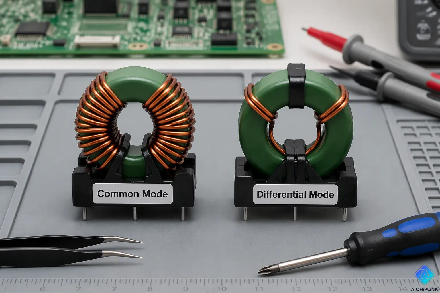
You face a simple choice when filtering electrical noise: common mode chokes handle currents flowing the same way on both wires, while differential mode chokes target currents flowing opposite ways. Think of two people walking side by side. Common mode means they walk together in one direction. Differential mode means they walk toward each other.
This difference matters because the wrong choke wastes your time and money. The global common-mode chokes market hit USD 674.2 million in 2024, according to Spherical Insights & Consulting, showing how many engineers rely on these parts. But you must first find out which way your noise current flows. That one step tells you which choke fixes your interference problem. Knowing this Key Differences idea saves you from costly trial-and-error.
Key Takeaways
-
First, figure out which way the noise is going. Common mode noise moves in the same direction on both wires. Differential mode noise moves in opposite directions. This single test shows you which choke to pick.
-
Common mode chokes have two windings that work together. They stop noise moving in the same direction but let your signal go through. This setup avoids core saturation and works great on data cables and power lines.
-
Differential mode chokes have just one winding. They add resistance to noise going in opposite directions. Use them with capacitors to clean up high-frequency ripple in power supplies.
-
Pick the choke that fits the noise you found. Use a current probe to test both wires at once. Then pick the choke that handles your main noise type for good filtering.
-
Real circuits often have both noise types. Use both chokes together for full EMI compliance. This combination covers the entire spectrum and ensures clean operation.
Key Differences: Common Mode vs Differential Mode Chokes
Common mode noise happens when equal currents move the same way on both wires. Differential mode noise happens when currents move opposite ways on those same wires. This one difference drives every key difference between the two choke types. You must figure out which noise pattern you have before you pick a part. That choice tells you whether you need a common mode choke or a differential mode choke for your circuit.
Noise Direction and Choke Response
The direction of unwanted current tells you which choke will work. Common-mode currents travel together on both lines, returning through a ground path instead of through the paired wire. Differential currents travel opposite ways, completing their loop through the supply and return wires. Your measurement goal is simple: probe both lines at the same time and see whether the noise currents line up or go against each other.
The choke's impedance response depends fully on this current direction. For differential mode currents with equal size but opposite directions, the magnetic fluxes made in the core cancel each other out. This cancellation creates very low impedance. The choke gives almost no resistance to these opposite-direction currents, letting them pass with little loss. You want this behavior for useful signals. Pick inductors with low differential mode impedance to reduce loss of your intended signal.
Common-mode currents give a different result. When both currents flow the same way, their fluxes add together instead of cancel. The choke then gives high impedance to this noise path. This high impedance stops the common-mode currents from moving further along your circuit. You effectively block that interference at the choke.
Winding Structure and Magnetic Behavior
The physical setup of windings on the core decides which mode the choke reduces. A common mode choke uses two coupled windings on one core. The winding direction follows a dot rule that marks the start of each coil. When dots sit on the same side of both coils, the magnetic fluxes point the same way and combine. This setup creates high impedance for common-mode currents while staying clear to differential signals.
When dots sit on different sides of the two coils, the fluxes push against each other. This opposing setup works for differential mode operation. The table below shows this relationship:
| Winding Orientation (Dot Convention) | Resulting Magnetic Flux Direction | Mode of Operation |
|---|---|---|
| Dots on the same side of the two coils | Flux directions are the same (combined) | Common mode |
| Dots on different sides of the two coils | Flux directions are not the same (opposing) | Differential mode |
You can see why common mode chokes are great at stopping high-frequency noise on power cables and signal connections. They block emi that lands on both lines equally. Differential mode chokes, on the other hand, add series impedance right in the path of opposite-direction currents. Each choke type handles one specific noise pattern, so you need to match the part to your measured current direction.
Real circuits often have both noise types at the same time. You may need both chokes working together to get clean operation at high frequencies. Start by finding which noise is stronger in your measurement, then choose accordingly.
What Is a Common Mode Choke?
A common mode choke is a passive part that removes unwanted electrical noise from paired wires. You put it in line with both wires of a cable. Its job is simple: stop noise that moves the same way on both lines while letting your intended signal pass through unchanged.
Coupled Windings on One Core
The common mode choke uses two windings on one magnetic core. This shared core is usually toroidal or E-shaped. You wrap each coil with insulated wire, placing one winding in series with each conductor of your paired cable. The core material is often ferrite, which works well with high-frequency noise.
Manufacturers use two main winding methods. Two-in-hand winding wraps both wires together through the core. This method gives you closely matched inductance for both wires, better circuit balance, and lower leakage. It costs more because someone must hand-wind it. Bank winding wraps an equal number of turns on opposite sides of the core. Machines can make this style cheaply, but you get higher leakage inductance and higher inter-winding capacitance.
The winding direction matters a lot. You must set the coils so that differential signal currents pass through them in opposite senses. When your desired signal flows, the magnetic fluxes from each winding point against each other. They nearly cancel inside the core. Your signal sees only small leakage inductance and winding resistance. The choke acts like a simple wire for the data or power you want to keep.
Common Mode Noise Suppression
Common-mode noise behaves differently. When common-mode currents enter both windings in the same direction, the fluxes add together instead of canceling. The choke now acts like a high-value inductor in series with each conductor. This high impedance blocks the noise path effectively.
The physics works because of flux addition. Common-mode currents create interference that the choke reduces. You get strong suppression without losing your signal quality. The core can hold very high inductance because the differential flux cancels, preventing saturation.
You must use common-mode chokes only on balanced conductor pairs. If one side sees different impedance to ground than the other, the balance breaks. This disruption causes mode conversion and parasitic coupling. Your filter performance drops. Always check both lines have symmetrical impedance to ground before installing the choke.
Common mode chokes excel at stopping ac line noise and high-frequency interference on data cables. They handle the noise that lands equally on both wires. You get clean operation without adding resistance to your useful signal.
What Is a Differential Mode Choke?
A differential mode choke stops noise that moves in opposite directions on two wires. Unlike the common mode choke, this part has a simpler design. You put it right in the path of the current you want to clean. Its main job is simple: block high-frequency interference while letting your useful signal pass through.
Single Winding in Series
You install a differential mode choke as one winding placed in series with your power or signal line. This winding wraps around a core, usually made of ferrite material. The design differs from common mode chokes, which need two coupled windings on one core. Here, you work with one coil carrying both your normal current and the unwanted noise.
The design demands careful attention to wire thickness. Since this single winding carries your full operating current, you need low DC resistance. High resistance would waste power as heat and reduce efficiency. You also must prevent magnetic saturation under peak current conditions. A saturated core loses its inductive properties entirely, leaving you with no filtering at all.
You often pair this choke with a capacitor connected from line to neutral. Together, they form a low-pass filter. This combination blocks high-frequency noise from traveling further along your circuit. The choke handles the inductive part of the filtering job, while the capacitor provides the shunt path for the noise to dissipate.
Differential Mode Noise Impedance
The choke works on a basic inductor rule: impedance rises with frequency. An inductor resists changes in current flow. When high-frequency AC noise tries to pass through, the winding creates back-EMF that fights the change. This opposition creates high impedance specifically for fast-changing signals.
For switching power supply ripple and differential-mode noise, this behavior proves useful. The choke presents high impedance to these unwanted currents, effectively blocking them. Low-frequency signals encounter minimal opposition and pass through with little loss. This frequency-dependent response makes the choke an excellent tool for smoothing current and reducing ripple.
The magnetic behavior explains why this works. When differential mode currents flow through the winding, they create magnetic flux in the core. This flux produces the inductive impedance that filters the noise. The choke dominates the differential-mode insertion loss in your circuit, meaning it provides most of the attenuation for opposite-direction interference.
You will find these chokes commonly placed in the power return line and power out line of power supplies. They excel at filtering high-frequency noise inherent to power conversion processes. For circuits with low DC or AC currents, they provide effective suppression without adding excessive bulk or cost to your design.
Side-by-Side Comparison of Chokes
You now know how each choke works. The next step is looking at them side by side. This helps you pick the right part for your noise problem quickly.
Noise Path, Winding, and Impedance
The table below shows the main differences between these two chokes. Use it as a quick guide when you check your circuit design.
| Feature | Common Mode Choke | Differential Mode Choke |
|---|---|---|
| Noise path | Same-direction currents on both conductors | Opposite-direction currents on the pair |
| Winding arrangement | Two coupled windings on one shared core | Single winding in series with one line |
| Magnetic behavior | Flux adds for common-mode noise, cancels for signal | Flux builds normally with load current |
| Impedance effect | High impedance to common-mode noise, low to signal | High impedance to high-frequency differential noise |
| Typical application | USB, SATA, HDMI, DisplayPort, AC power inlets | Individual power or signal lines |
The winding polarity causes these differences. In a common-mode choke, the two windings make opposing flux for your load current. This cancels out and stops core saturation. It also gives you high impedance for common-mode noise. A differential-mode choke has just one winding. Its design gives impedance straight to opposite-direction currents. You also get some leakage inductance from a common-mode choke, usually a few µH to 100 µH. This leakage acts like a small differential-mode inductor in series with your circuit.
Applications and Filtering Role
You will find common mode chokes on fast signal interfaces like USB, SATA, HDMI, and DisplayPort. These interfaces use differential signals, but the noise on them is mostly common mode. The choke stops that noise without changing your signal, even when signal and noise frequencies overlap. You also see common mode chokes on power inlet cables and AC adapters. Large currents flow through these lines. The choke handles them well because the differential-mode flux cancels, so it does not saturate. A ferrite bead or normal mode choke would not work as well under those same conditions.
Differential mode chokes show up more often in series with single power or signal lines. They filter the ripple and switching noise that power supplies make. You pair them with capacitors to form low-pass filters that block high-frequency interference. For EMC compliance, you often need both types. Real circuits have both common-mode and differential-mode emissions. A common-mode choke handles the same-direction noise, while a differential-mode choke cleans up the opposite-direction currents. Together, they give you full filtering across the spectrum.
How to Choose the Right Choke
You must find the noise path before picking any part. Use a current probe and check both wires at the same time. If the noise currents move the same way on both wires, pick a common-mode choke. If they move opposite ways, a differential mode choke works better. This one test decides your choice.
Identify the Noise Path and Frequency
Use a three-step process for your power supply EMI filter. First, find out how much noise you need to block. This number sets the choke's impedance. Second, find the lowest frequency of the noise you must stop. This sets the choke's frequency range. Third, figure out the current the choke must carry. This limits where you can use the part.
Frequency shows which mode is stronger. In switching power supplies, differential mode noise is usually higher at lower frequencies. Common mode noise sits higher at upper frequencies. You measure conducted emissions from 150 kHz to 30 MHz with a LISN and spectrum analyzer. This test shows which noise type causes your issue.
A simple rule: the lower the frequency you filter, the bigger the choke must be. For DC power supplies, audio frequency (AF) chokes with solid ferrite cores usually beat RF chokes with powdered iron cores. They give higher saturation flux density and current rating.
You also need two key features from your common-mode choke. First, check differential mode insertion loss. The choke must have low loss at the signal frequency to keep signal quality, including voltage amplitude and jitter. The cut-off frequency is where insertion loss hits -3dB. Second, check common mode insertion loss. The choke must have high loss at the noise frequency, since most serious noise travels as common mode.
Match Ratings and Verify EMI Performance
Match your choke ratings to real operating conditions. The current rating must handle the maximum current during normal use. Power dissipation must stay acceptable during that use. Saturation current is usually not a problem for common-mode chokes because little current flows in common mode.
But power supply lines carry large differential mode currents. These currents create magnetic flux leakage that can cause saturation. A saturated core loses its inductive properties and your filtering fails. Use the choke within the range that avoids performance drops from magnetic saturation.
Voltage ratings follow your mains supply. For a 230 V AC system, typical clearances of about 2.5 mm and creepage distances between roughly 1.25 and 4 mm are required per IEC 60638, depending on insulation material and pollution degree.
After installing your filter, check performance against CISPR 32 Class B limits. Use an EMSCOPE instrument with a two-port LISN and two EMI receivers. This setup measures QPK and CAVG detectors on both Line and Neutral terminals at the same time. Measure initial conducted emissions to find the non-compliant frequency range. Use spectrogram analysis to capture time-varying emissions and find the worst-case operating mode. Separate common-mode and differential-mode emissions to see which dominates.
A typical power-line filter might include an X-type capacitor of 470 nF, a common-mode choke of 1.5 mH, two Y-type capacitors of 4.7 nF, and a 1 MΩ resistor. After adding this filter, confirm compliance by measuring both power lines together. The device should show full EMC compliance with CISPR 32 Class B conducted emission limits.
Real-world EMI often has both noise types. Many designs use a common-mode choke and a differential mode choke together. The common-mode choke handles same-direction noise on the pair. The differential mode choke cleans up opposite-direction currents. Together, they cover the full spectrum and give you clean operation.
Identify the unwanted current direction before selecting any part. That single measurement determines whether you need a common mode choke or a differential mode choke. Common mode chokes target same-direction noise on paired conductors. Differential mode chokes handle opposite-direction noise in your signal or power path.
Verify your choice with real measurements rather than guessing. Use clip-on RF current probes to check noise paths without breaking your conductors. For common mode noise, clamp the probe around individual wires. For differential mode, clamp around both conductors together. Then measure insertion loss with S-parameter tools that match your actual source and load impedances. This approach confirms your choke selection works under real operating conditions.

Written by Jack Elliott from AIChipLink.
AIChipLink, one of the fastest-growing global independent electronic components distributors in the world, offers millions of products from thousands of manufacturers, and many of our in-stock parts is available to ship same day.
We mainly source and distribute integrated circuit (IC) products of brands such as Broadcom, Microchip, Texas Instruments, Infineon, NXP, Analog Devices, Qualcomm, Intel, etc., which are widely used in communication & network, telecom, industrial control, new energy and automotive electronics.
Empowered by AI, Linked to the Future. Get started on AIChipLink and submit your RFQ online today!
Frequently Asked Questions
Can I use a common mode choke for differential mode noise?
No. A common mode choke cancels flux for opposite-direction currents, so it offers almost no impedance to differential noise. You need a separate differential mode choke for that path. Using the wrong part leaves your noise unfiltered and wastes board space.
How do I measure which noise type I have?
Clamp a current probe around both conductors together. Differential mode currents cancel in the probe reading. Common mode currents add together and show a strong signal. Then clamp around a single wire. A reading there confirms common mode noise exists on that line.
What happens if my choke saturates?
A saturated core loses its inductive properties completely. Your filtering stops working, and noise passes straight through. Check your peak current against the choke's saturation rating. For common mode chokes, saturation rarely happens because differential flux cancels. For differential mode chokes, verify your maximum load current stays below the rated limit.
Do I always need both choke types in my design?
Most real circuits produce both noise patterns simultaneously. Switching power supplies generate differential ripple at lower frequencies and common mode noise at higher frequencies. You often need both chokes working together. Measure your emissions first, then add the choke that targets your dominant noise problem.
Why does winding direction matter on a common mode choke?
The dot convention sets which way each coil wraps around the core. Correct orientation makes differential signal fluxes cancel, so your data passes cleanly. Wrong orientation makes those fluxes add, creating unwanted impedance that degrades your signal. Always verify the datasheet's winding diagram before installation.