Capacitor Networks Complete Guide for Beginners
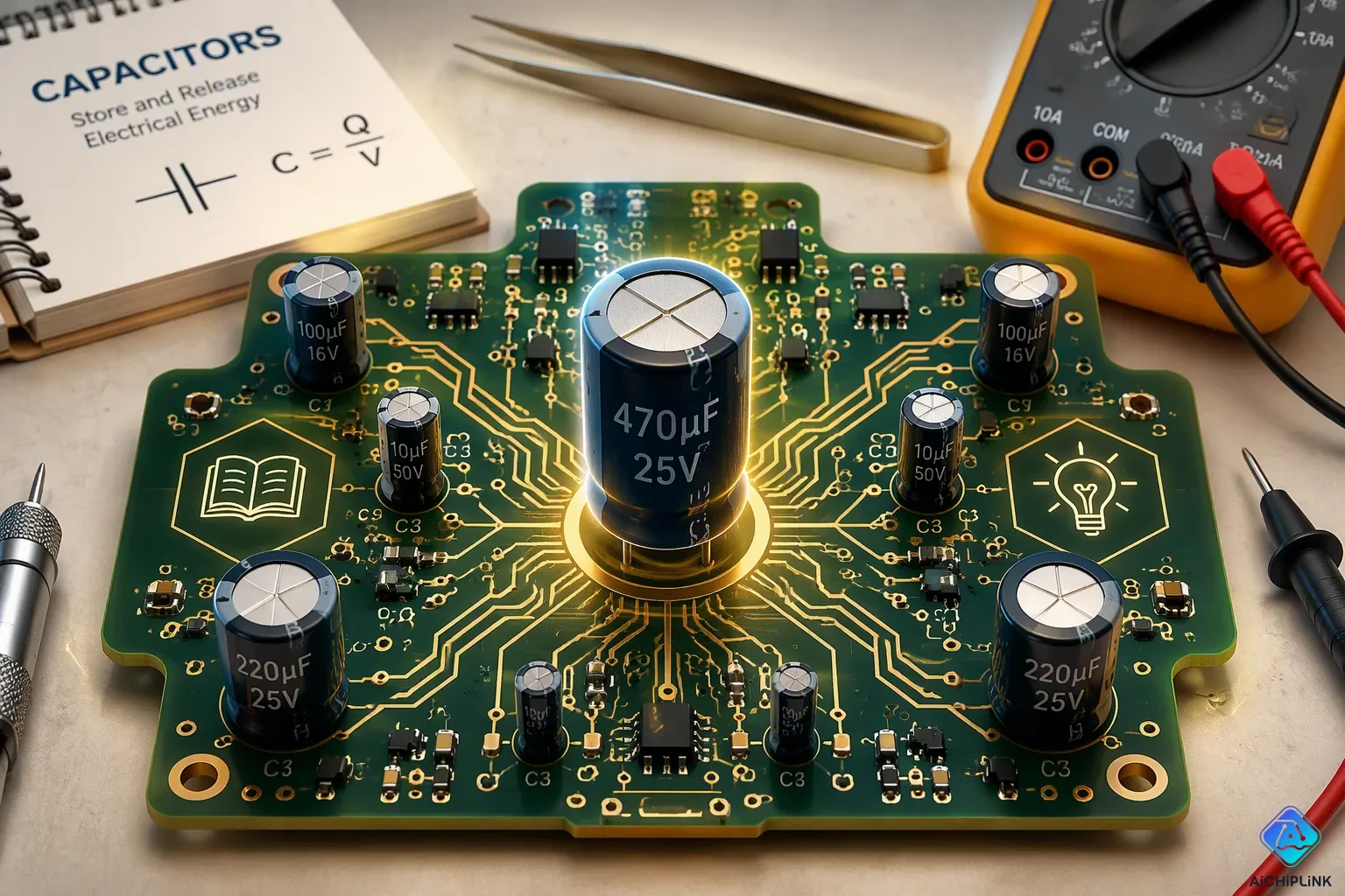
This is your Capacitor Networks Complete Guide, your one-stop resource for understanding what a capacitor network is and why you need one. At its core, a capacitor network is simply a group of capacitors linked together to achieve a specific total capacitance or a higher voltage rating. To visualize it, think of water tanks: connecting them in parallel stores more total water (more capacitance), while stacking them in series allows the system to handle higher water pressure (higher voltage). In practical circuits, you’ll often see common capacitance values like 0.1 µF used for decoupling noise, and 100 µF for smoothing out power supply ripples—these are perfect starting points for beginners working with capacitors. These networks appear everywhere, from power adapters to audio equipment. In this Capacitor Networks Complete Guide, you’ll master the essential formulas for series and parallel configurations, learn how to break down and solve mixed networks step by step, and explore real-world uses like signal filtering. By the end, you’ll have the skills and confidence to design your own custom capacitor network from scratch. Let’s get started.
Key Takeaways
-
Capacitor networks put capacitors together to reach a desired capacitance or voltage rating.
-
When capacitors are connected in series, the voltage rating goes up, but the total capacitance goes down.
-
Parallel connections increase total capacitance while keeping the same voltage rating.
-
Solve mixed networks by making inner groups simpler, one step at a time.
-
Use capacitor networks to filter power and time circuits.
What Are Capacitor Networks?
Before you can master capacitor networks, you need to understand the building block: a single capacitor. Think of a capacitor as a tiny rechargeable energy reservoir. It consists of two conductive plates separated by an insulating material called a dielectric. When you apply a voltage across the plates, an electric field forms, and the capacitor stores energy in that field. The amount of energy a capacitor can hold depends on three factors: the surface area of the plates, the distance between them, and the dielectric material itself.
The dielectric material plays a starring role in determining capacitance. Different materials have different dielectric constants (κ), which measure how well they support an electric field. Here's a quick look at some common materials:
| Material | Dielectric Constant (κ) |
|---|---|
| Vacuum | 1.00000 |
| Air | 1.00059 |
| Teflon | 2.1 |
| Polystyrene | 2.56 |
| Paper | 3.7 |
| Pyrex glass | 5.6 |
| Water | 80 |
| Strontium titanate | 233 |

As you can see, the dielectric constant varies dramatically. A capacitor with strontium titanate as its dielectric can store far more energy than one using air, given the same physical size. This property explains why engineers choose different materials for different jobs.
Now, when you connect multiple capacitors together, you create what we call capacitor networks. These arrangements let you customize the total capacitance, share voltage stress, or improve reliability in ways a single component cannot achieve alone.
How Capacitors Work
A capacitor stores electrical energy in an electric field between its two plates. When you connect a voltage source, electrons accumulate on one plate, creating a positive charge on the opposite plate. This charge separation creates the electric field that holds energy. The capacitance value, measured in farads, tells you how much charge a capacitor can store per volt of applied voltage.
The common types of capacitors you will encounter as a beginner include ceramic and electrolytic versions. Ceramic capacitors offer capacitance values from picofarads to a few microfarads. They are non-polarized, meaning you can connect them in either direction. Electrolytic capacitors provide much higher capacitance values, often from 1 µF to 1 mF, making them suitable for bulk energy storage. However, electrolytic capacitors are polarized, so you must connect them with the correct polarity or risk damaging them.
These two types serve different purposes. Ceramic capacitors excel at filtering high-frequency noise and decoupling signals. Electrolytic capacitors handle low-frequency ripple and store larger amounts of energy. Understanding these differences helps you choose the right component for your circuit.
Why Use a Capacitor Network
You might wonder why you cannot simply pick one capacitor with the exact value you need. Sometimes, the perfect single capacitor does not exist. Other times, you need to combine capacitors to meet specific requirements that one component cannot satisfy alone.
One primary reason to build capacitor networks involves voltage ratings. When you connect capacitors in series, the total voltage rating increases because each capacitor shares the voltage drop. This arrangement proves essential in high-voltage circuits where a single capacitor would fail. Conversely, connecting capacitors in parallel increases the total capacitance while maintaining the same voltage rating. This configuration works well when you need more energy storage than one capacitor provides.
Another practical reason involves performance at different frequencies. In power supply filtering, engineers often combine a large electrolytic capacitor with a small ceramic capacitor in parallel. The large capacitor handles low-frequency ripple, while the small one filters high-frequency noise. Each capacitor has a self-resonant frequency (SRF), and combining them provides separate paths for different frequency ranges. This dual-capacitor approach improves filtering effectiveness in precision circuits.
Consider an audio amplifier circuit. A single capacitor might not handle the required voltage or provide the necessary filtering across the entire frequency range. By using capacitor networks, you can achieve the exact capacitance and voltage handling needed. For example, a typical decoupling setup might use a 0.1 µF capacitor for frequencies below 10 MHz and a 1–10 µF capacitor for frequencies above 20 MHz. These combinations remove unwanted noise effectively.
The energy stored in capacitor networks also matters for real-world applications. Electrolytic capacitors store significant energy for power supply smoothing, while ceramic capacitors handle rapid charge and discharge cycles. By combining different types, you gain the benefits of each while minimizing their individual weaknesses.
Capacitor networks also improve reliability. If one capacitor fails in a parallel configuration, the others continue functioning, providing redundancy. In critical systems, this redundancy can prevent complete circuit failure.
Finally, you might need a non-standard capacitance value. Standard capacitors come in specific values, but you can create almost any capacitance by combining standard parts. For instance, placing two 10 µF capacitors in parallel gives you 20 µF, and adding a 2.2 µF capacitor in parallel yields 22.2 µF. This flexibility lets you fine-tune your circuit without waiting for custom components.
Understanding capacitors in series and capacitors in parallel gives you the foundation for designing these networks. You will learn the exact formulas for these configurations in the next section, along with methods for solving more complex mixed networks.
Series vs. Parallel Configurations
Now you will learn the two main ways to connect capacitors. These setups are the basic parts of every capacitor network you will see. Knowing both helps you build circuits that meet exact voltage and capacitance needs.
Series Capacitors
When you connect capacitors end-to-end, you make a series setup. This shares voltage across each part. Total capacitance goes down, but voltage rating goes up. Two same capacitors in series cut capacitance in half but double the voltage they can handle. This matters when one capacitor cannot take the needed voltage.
The formula for total capacitance in a series network uses a reciprocal relationship:
The total capacitance in a series network is given by the reciprocal sum: 1/CS = 1/C1 + 1/C2 + 1/C3 + …
This formula comes from how charge stays the same. In a series capacitor network, all capacitors hold the same charge Q because the middle wires are isolated. The total voltage across the group equals the sum of each voltage: V = V1 + V2 + V3. Using the capacitor voltage rule V = Q/C, you swap in to get Q/CS = Q/C1 + Q/C2 + Q/C3. Removing the shared charge Q from both sides gives the reciprocal formula.
Real-world uses for series setups include high-voltage power generation. Series capacitor banks show up in Cockcroft–Walton multipliers, X-ray machines, and particle accelerators running at hundreds of kilovolts. The series link raises the total voltage rating, letting each capacitor share the load while changing AC input to DC output.
Series links also help isolate signals in audio gear. Coupling capacitors placed in series block DC bias from reaching speakers or amplifiers, cutting distortion and stopping offset damage. In fast data transfer, series capacitors block DC parts in transmission lines, keeping signals clean. Power amplifier output stages use big electrolytic capacitors in series with the signal path to block DC while letting low-frequency audio signals pass.
Parallel Capacitors
When you connect capacitors side by side, you make a parallel setup. Each capacitor sees the same voltage. The total capacitance adds up, giving you more energy storage.
The total capacitance of capacitors in parallel is calculated as: Ctotal = C1 + C2 + C3 + … + Cn
This means the total capacitance is just the sum of each capacitor's value connected in parallel. For example, putting two 10 µF capacitors in parallel gives you 20 µF of total capacitance.
Parallel setups shine in DC power supply filtering. A layered decoupling plan uses many parallel capacitors to handle different frequency ranges. Bulk capacitors (electrolytic or tantalum, 10–100 µF) sit near the power entry point to handle low-frequency ripple. Mid-value ceramics (1–10 µF) place near device groups to manage medium-frequency spikes. Small MLCCs (0.01–0.1 µF) sit right at IC power pins to stop high-frequency switching noise.
This multi-layer parallel setup keeps low impedance across a wide frequency range. In DC power supplies for digital systems, switching spikes happen when logic gates flip, causing fast current changes. Without local support, this leads to voltage drops and jitter. Parallel capacitors act as local energy stores that give burst current to keep voltage steady and send high-frequency noise to ground. For analog circuits on the same supply, parallel capacitors smooth out ripple and keep bias stable.
The energy stored in capacitor networks depends on which setup you pick. Series setups trade capacitance for voltage handling. Parallel setups boost capacitance while keeping the same voltage rating. Your circuit needs decide which setup fits. High-voltage uses need series links. High-capacitance filtering needs parallel links. Many circuits mix both ways to get the best results.
Solving Mixed Networks
Real circuits rarely use only one setup. You will often see capacitor networks that mix series and parallel parts. To solve these mixed networks, you need a clear plan, not guesswork.
Step-by-Step Method
You can solve any mixed network by starting from the inside and moving outward. First, find the innermost group of capacitors. Look for sets that connect only in series or only in parallel. Use the right formula to find the equivalent capacitance for that group. Then, swap that group with one equivalent capacitor. Keep doing this until the whole network becomes a single capacitance value.
For capacitors in series, use the reciprocal sum formula. For capacitors in parallel, just add the values. The main point is that you never use both formulas at the same time. You always handle one small section at a time. This step-by-step method cuts down on mistakes and makes complex networks easier to handle.
Think of this process like peeling an onion. Each layer you remove makes the circuit simpler. You keep going until only one capacitor is left. That single value stands for the total capacitance of the whole network.
Worked Example
Let us go through a real example to see how this works. You have three capacitors: C1 = 10 µF, C2 = 10 µF, and C3 = 100 µF. C1 and C2 connect in series, and that pair connects in parallel with C3.
-
Combine the series pair: For C1 and C2 in series, you find the reciprocal of the equivalent capacitance: 1/CS = 1/10 + 1/10 = 0.2 per µF. Flipping this value gives CS = 5 µF.
-
Combine with the parallel capacitor: The series equivalent CS now sits in parallel with C3. You add them directly: Ctot = 5 µF + 100 µF = 105 µF.
-
State the final result: The total capacitance of this mixed network equals 105 µF, rounded to the nearest microfarad.
This example shows how mixed capacitor networks reduce to one value. You first deal with the capacitors in series, then combine that result with the capacitors in parallel. The order matters because you must follow the circuit layout.
Practice this method with different values and setups. You will soon spot patterns in how capacitor networks fit together. This skill helps you build circuits that meet exact capacitance needs without hunting for rare component values.
Applications of Capacitor Networks
Capacitor networks are found in almost every electronic device you use. Two key areas where these networks are especially useful are power supply filtering and timing circuits.
Power Supply Filtering
The most common use of capacitor networks is smoothing out power supply ripple. This is one of the most important jobs capacitors do in electronics. When a rectifier changes AC to DC, the output still has voltage changes called ripple. A single capacitor gives basic smoothing by charging and discharging, but it leaves some ripple that depends on load current and capacitance. However, bigger capacitors cost more and need more space.
Engineers fix this by building networks. An LC filter adds a series inductor that resists current changes, blocking high-frequency AC ripple while the component sends leftover voltage ripple to ground. This mix smooths both current and voltage. For even better results, a Pi (CLC) filter uses three stages: the first stage does bulk filtering, the inductor reduces the AC part, and the last stage gives fine filtering. This step-by-step method gives the best ripple reduction for sensitive circuits.
These networks show up in power supplies for computers and appliances. They stop voltage changes and keep things running steady. In motherboards, GPU modules, and RAM boards, capacitor networks keep voltage stable for fast, reliable performance. Audio gear uses them to filter noise and keep sound clear. Communication devices depend on them for clean signals.
Timing and Signal Circuits
These networks also set timing in circuits like the 555 timer. In the standard astable setup, the capacitor charges through resistors RA and RB until it hits 2/3 of the supply voltage. At that point, the output goes LOW and the discharge transistor turns on. It then discharges through RB only until it reaches 1/3 Vcc, then the output goes HIGH again and the cycle starts over.
The timing formulas use simple math. In astable mode, the high time is proportional to (R1 plus R2) times C, and the low time is proportional to R2 times C. In monostable mode, the output pulse width is proportional to R times C. The capacitance value directly changes these timing intervals.
Signal filtering is another common use. In audio circuits, parts block DC while letting AC signals pass. This removes unwanted DC offset and stops distortion. In communication devices, networks filter noise and boost signal clarity. Using different capacitors in a network handles both low-frequency and high-frequency noise, giving you cleaner output across the whole signal range.
Common Mistakes and Troubleshooting
When building capacitor networks, beginners often make errors that damage parts or ruin circuit performance. Two common problem areas are polarity and voltage ratings. This section covers the main pitfalls and gives troubleshooting capacitor networks guidance. It also shows you how to test your networks safely. Understanding these issues helps you avoid costly mistakes. Proper troubleshooting saves time and prevents damage.
Polarity and Voltage Ratings
One of the most common mistakes is putting polarized capacitors in backwards. Electrolytic and tantalum capacitors have a positive and negative lead. Connecting them the wrong way causes serious problems. The results follow a clear chain:
-
Capacitor Breakdown: Reverse voltage beyond rated limits breaks down the oxide layer on the dielectric. This leads to catastrophic failure—leakage, short-circuiting, or explosion.
-
Loss of Capacitance: Reversed polarity changes how the dielectric behaves. This greatly reduces effective capacitance, hurting energy storage and filtering.
-
Leakage Current: Reverse-biased capacitors create leakage current. This upsets circuits that need precise voltage regulation or signal processing.
-
Circuit Malfunction: Wrong orientation disrupts coupling and decoupling. This causes DC offset and signal integrity issues. AC signals also suffer from this problem.
Reversed polarity starts a failure chain: Dielectric breakdown (oxide layer damage under reverse voltage stress) leads to much higher leakage current, then heat buildup, then internal expansion and deformation. This results in swelling, leaking, or explosion. The physical damage can hurt nearby components and cause whole circuit failure. Even without quick failure, ongoing leakage slowly degrades performance.
You must also respect voltage ratings. Each capacitor has a maximum voltage it can handle. Going past this rating causes instant failure. When building a series setup, the voltage split depends on each capacitor's value. Unequal capacitors share voltage unevenly. Always check that no single capacitor goes over its rated voltage. Knowing polarized vs non-polarized capacitors helps you pick the right part for each job.
Testing a Capacitor Network
Testing your network after assembly confirms it works right. Use a multimeter with capacitance measurement mode. Follow these steps for safe and accurate testing:
-
Discharge the capacitor: After removing power, use a suitable resistor to discharge the capacitor safely. Then use the multimeter to confirm the capacitor is fully discharged.
-
Set up the multimeter: Turn the dial to Capacitance Measurement mode. Press the needed function button as shown in your user manual.
-
Detach the capacitor: Remove the capacitor from the circuit to avoid measurement errors. Testing in-circuit gives wrong readings.
-
Connect the leads: Attach the test leads to the capacitor terminals. Keep them connected for a few seconds to allow auto-ranging.
-
Read the results: Check the displayed value. 'OL' means an out-of-range value or a faulty capacitor.
-
Use Relative mode if needed: For low capacitance values, turn on Relative mode to make up for test lead capacitance.
Regular testing helps you catch problems early. Troubleshooting capacitor networks becomes easier when you check each component on its own. This saves time and prevents circuit damage. Methodical checks and safety practices prevent damage.
Helpful Tools for Beginners
You don’t have to remember every formula to work with capacitor networks. Many free online tools can do the math for you. These calculators let you focus on understanding the circuit design instead of struggling with reciprocals. They also work great for checking answers when you solve problems by hand.
Online Capacitance Calculators
Many free online calculators can help you with capacitor networks. They give fast, accurate results for designing circuits or fixing existing ones. Just enter your capacitor values, and the tool does the rest.
Several free options are available for different needs. Some offer a visual way to build and test circuits online, while others handle series and parallel setups easily. You enter values, and they show the total capacitance right away.
These tools are very helpful when you design networks with many parts. You can try different values quickly without doing manual math. First solve a problem by hand, then check your answer with one of these calculators. This practice builds your skills and confirms you understand the material.
Using a Multimeter
A multimeter with a capacitance mode gives you a strong way to check your work. You can test single capacitors or whole networks to see if they match your design. This step catches mistakes before you put the network into a circuit.
Start by safely discharging the capacitor. Use a suitable resistor to discharge the capacitor after turning off power. Then set your multimeter to capacitance mode. Remove the capacitor from the circuit before testing, because in‑circuit readings are not accurate. Connect the test leads and wait a few seconds for the meter to settle. The screen shows the measured capacitance. An "OL" reading means the value is out of range or the part is bad.
For low capacitance values, use Relative mode to adjust for the leads’ own capacitance. This feature subtracts the leads’ built‑in capacitance from your reading. Testing regularly helps you make sure your capacitor networks work as planned. You build confidence in your projects and catch issues early.
You now know how capacitor networks let you change the capacitance and voltage they can handle. This guide covered the formulas for series and parallel setups. For series, you use a special reciprocal sum. For parallel, you just add the values. Mixed networks are solved by working from the inside out, one step at a time.
Always follow voltage ratings and polarity rules. Electrolytic capacitors must be connected the right way. Discharge each capacitor before touching it to stay safe. These habits prevent damage and help you fix problems with capacitor networks.
This guide showed real uses for capacitor networks in DC power filtering and AC signal coupling. You also learned practical ways to find and fix problems.
Now try building a simple network using ceramic and electrolytic capacitors. Try different combinations. See the theory work in real life. Leave any questions in the comments below.

Written by Jack Elliott from AIChipLink.
AIChipLink, one of the fastest-growing global independent electronic components distributors in the world, offers millions of products from thousands of manufacturers, and many of our in-stock parts is available to ship same day.
We mainly source and distribute integrated circuit (IC) products of brands such as Broadcom, Microchip, Texas Instruments, Infineon, NXP, Analog Devices, Qualcomm, Intel, etc., which are widely used in communication & network, telecom, industrial control, new energy and automotive electronics.
Empowered by AI, Linked to the Future. Get started on AIChipLink and submit your RFQ online today!
Frequently Asked Questions
What formula does this capacitor networks complete guide teach for series?
The reciprocal sum formula helps you find the total value for series networks. You take 1 and divide it by the sum of each capacitor's reciprocal. Start with small networks to practice.
How does parallel differ from series in capacitor networks?
Parallel adds up each capacitor's value. Every capacitor gets the same full voltage. This gives you more total energy for filtering needs.
What is troubleshooting for capacitor networks?
Begin by checking each capacitor for faults. Test polarity on electrolytic capacitors. Make sure voltage ratings are correct. Use a multimeter set to measurement mode.
Do capacitors in series or parallel give larger total values?
Parallel capacitors give larger total capacitance values. You add each value directly. Series capacitors make the total value smaller than the smallest part.