MLCC vs Polymer Tantalum Capacitors for Solving 2026 Circuit Challenges
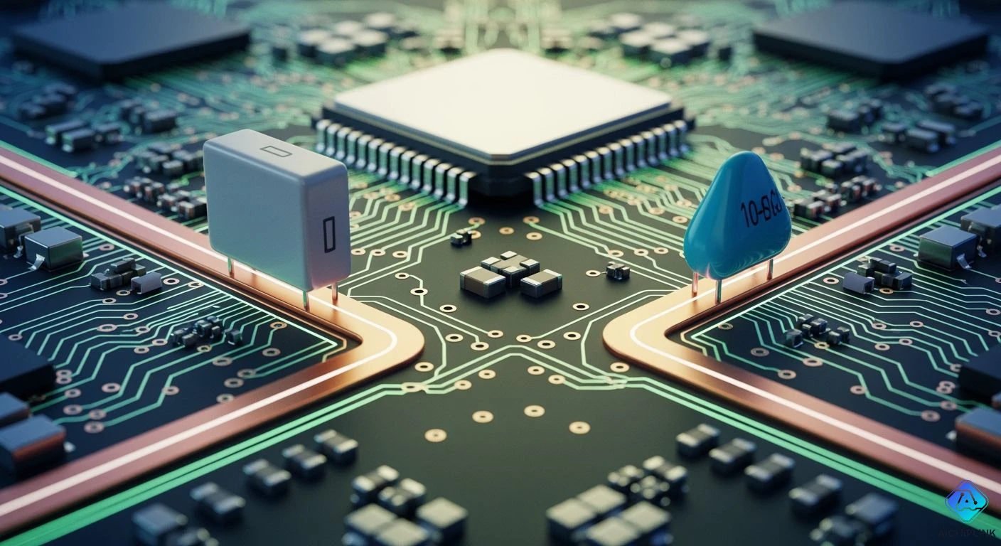
Tiny circuit board designs face tough power delivery problems in 2026. Sudden voltage spikes, vibration noise, and supply delays can ruin system stability. You can use polymer tantalum capacitors for high-density energy storage because they do not lose capacity under DC voltage. Meanwhile, you keep MLCCs near the chip to handle fast, high-frequency electrical noise.
Evaluating MLCC vs Polymer Tantalum Capacitors shows major differences in power delivery. Standard ceramic capacitors lose their ability to hold charge when voltage is applied. However, conductive polymer tantalum parts maintain stable performance even when temperatures change. Experts predict strong market growth for these polymer parts through 2033. Using both capacitor types creates an optimal power network.
Key Takeaways
-
Polymer tantalum capacitors keep a steady power supply under high DC voltage.
-
Small MLCCs quickly soak up electrical noise right next to chip pins.
-
Swapping out sets of MLCCs for a single polymer tantalum capacitor frees up circuit board space.
-
Using both capacitor types together creates a steady and quiet power system.
2026 Circuit Design Challenges
DC Bias Degradation Issues
Today's crowded circuit boards put intense stress on your power delivery systems. You frequently lose lots of storage capacity when sending DC voltage through high-density ceramic capacitors. Certain ceramic materials lose much of their actual storage ability under regular working voltages. This surprising loss forces engineers to crowd extra parts onto power lines. You have to add extra storage space just to keep central system voltages at safe levels.
Polymer tantalum capacitors solve this voltage-driven loss problem entirely. Their solid conductive center keeps storage levels steady, no matter how much voltage you apply. You get reliable performance across your whole voltage range without needing extra parts. Switching to these capacitors lets you lower the total number of parts on your board. You get stable power storage while fitting essential noise-filtering parts into tight spaces.
Microphonics and Real-Estate Constraints
Small electronic designs also struggle with physical shaking and limited board space. Standard ceramic capacitors create unwanted electric signals whenever they bend or flex. Shaking and flexing convert into extra electrical noise inside these ceramic parts. Audio tools, sensors, and delicate analog systems pick up annoying hums and power disruption. Plus, lining up dozens of small MLCCs eats up vital circuit board space. Adding this many parts makes wiring around fast processor chips very difficult.
Swapping groups of side-by-side ceramic capacitors for one polymer tantalum part solves layout and noise issues together. Conductive tantalum materials do not react to physical stress, which stops noisy vibration completely. Your device maintains clean signals even when exposed to strong shaking. At the same time, placing one tiny capacitor near the processor pin manages fast electrical noise. This smart combination saves valuable board space while meeting local power needs across your board.
MLCC vs Polymer Tantalum Capacitors: Key Differences
Comparing mlcc vs polymer tantalum capacitors shows big electrical differences and performance traits in modern circuit designs. High-frequency setups need accurate filtering to keep the power distribution network stable. Polymer tantalum capacitors easily match MLCC frequency response patterns in middle-frequency ranges. Yet, MLCC technology offers lower raw equivalent series resistance and lower equivalent series inductance. These special traits make MLCC units much better for ultra-high-frequency decoupling. You can place MLCC parts right beside processing pins to soak up fast switching spikes.
Electrical Performance Breakdown
Learning key differences in capacitor performance helps you pick the right part for every capacitor stage. High-density designs often fail when parts lose electrical storage under normal working conditions. Polymer tantalum components keep steady capacitance density across high working temperatures. Standard multi-layer ceramic capacitors excel at local noise reduction thanks to ultra-low impedance. Mixing both technologies provides your power supply network with steady energy storage and high-frequency decoupling.
| Capacitor family | DC-bias stability | Temperature stability |
|---|---|---|
| Tantalum (includes polymer tantalum) | Fairly predictable under DC bias when used inside rated voltage and heat limits; skips MLCC-style DC-bias loss, so it stays more predictable on a DC rail. | Must still be chosen using datasheet values at the real working heat, frequency, and ripple conditions. |
| Class 2 MLCC | Can lose major working storage as DC bias goes up; case size, rated voltage, material, and applied-voltage ratio set the loss. | C0G/NP0 is much more stable; Class 2 heat traits need checking in the datasheet, while physical cracking and DC-bias loss cause main design risks. |
You need to check overall impedance curves to guarantee smooth power delivery. Polymer tantalum units cut down high-frequency ripple while giving you bulk energy storage. At the same time, ceramic capacitors manage sudden transient currents during quick switching events. Saving standard MLCC units for focused decoupling tasks keeps power extra clean.
Multilayer Ceramic Capacitors Dielectric Behavior
Material choice directly changes how ceramic capacitors react under heat stress. Class 2 multilayer ceramic capacitors use ferroelectric materials that respond strongly to active electric fields. You should check specific electrical settings before approving a final board design.
-
X7R works from −55°C to +125°C, but X5R works from −55°C to +85°C.
-
Class 2 ceramic capacitors lose 10% to 90% of their marked storage at full DC voltage because inner electrical pairs align and lock up.
-
X8R offers higher-temperature performance up to 150°C with a ±15% storage limit.
-
Engineers need to lower voltage to at least 2× working voltage to reduce the electric field and protect storage stability.
-
Testing tools like Murata SimSurfing or KEMET K-SIM check real working storage under actual circuit conditions.
Applying DC bias aligns internal parts inside Class 2 ceramic materials. This physical action lowers extra permittivity and reduces true storage space. Smaller case sizes lose even more storage at full working voltage. You can avoid power drops by putting polymer tantalum capacitors on main voltage rails for steady energy flow. This swap method removes unexpected losses while letting small MLCC parts handle high-frequency decoupling.
Checking mlcc vs polymer tantalum capacitors shows clear differences in power network design. Tantalum capacitors offer predictable storage under steady DC bias. Ceramic capacitors deliver low impedance for local decoupling. Understanding these basic behavior traits lets you construct safe, compact circuits for tough 2026 uses.
Reliability and Failure Modes
MLCC Cracking vs Polymer Stability
Board flexing during manufacturing places standard MLCC parts in real danger. Ceramic bodies handle pushing forces well, but pulling stresses snap these brittle components. Soldering, snapping boards apart, tightening screws, and heat changes bend your circuit board. This bending force creates tiny hidden cracks inside the ceramic layers. Eventually, these hidden cracks cause dangerous short circuits or complete board failures. Smart engineers place ceramic parts very carefully to prevent mechanical damage.
Polymer tantalum capacitors solve these physical bending problems completely. Their solid build guards your circuit board during production and daily use. These solid parts never dry out or explode like wet capacitors. You get much stronger physical reliability on bending boards during fast manufacturing. Swapping out weak parts for polymer units gives your device great strength against shaking.
Overvoltage and Self-Healing Mechanisms
Parts slowly change how they hold charge over long periods of use. Class 2 ceramic capacitors lose energy storage predictably as crystal patterns relax inside. Most parts lose about 1% to 5% of their storage every ten years. After 10 years, X7R keeps about 94-97% storage, X5R holds 88-94%, and Y5V keeps 82-88%. Class 1 C0G parts never lose storage space this way.
-
Class 2 ceramic parts lose total electrical storage slowly during long periods of active use.
-
Polymer tantalum units show zero regular wear-out issues during normal daily electrical work.
-
Heat testing at full voltage shows polymer parts last for hundreds of thousands of hours.
Polymer tantalum capacitors also repair themselves when sudden power spikes hit the system. The conductive polymer turns into a protective shield whenever tiny flaws appear inside. This quick fix closes off damaged spots before shorts can form. You protect delicate power lines while keeping your device running smoothly without stops. Choosing strong capacitors ensures reliable main power delivery over many years of use.
Strategic Component Substitution Rules
You can upgrade your circuit layout by swapping several ceramic capacitors for new polymer tantalum units. Choosing new parts means you must carefully follow specific voltage reduction guidelines. Old MnO2 tantalum parts need a 50% voltage cut to avoid electrical damage. Modern polymer tantalum options handle higher working voltages much more safely. Lowering applied voltages correctly keeps your system safe from unexpected power spikes.
Voltage Derating and Polarity Rules
You should figure out safe limits before changing components on live power lines. Every polymer tantalum capacitor needs a set voltage drop based on its original rating. Following these factory instructions keeps part temperatures down while your device runs constantly.
| Voltage derating category | Exact derating rule | Reliability benefit |
|---|---|---|
| Parts rated ≤10 V | Apply up to 90% of rated voltage | Prevents excessive voltage stress when replacing ceramic capacitors. |
| Parts rated >10 V | Apply up to 80% of rated voltage | Protects power rails against overvoltage breakdown. |
| Traditional MnO2 tantalum | Apply 50% voltage derating | Reduces thermal failure risks during high power spikes. |
Always check part alignment because polymer tantalum options only work in one direction. Standard EIA sizing codes, such as KEMET A/3216-18, B/3528-21, and C/6032-28, show exact physical dimensions. Designers must double-check footprint drawings to get strong solder connections on the pcb. Check overall circuit opposition to keep control systems running smoothly. Putting a single mlcc next to sensitive pins handles fast local electrical noise well. Viewing this part swap as a full circuit update stops sudden power failures and heat damage.
Footprint Consolidation Techniques
Crowded circuit boards lose valuable space when you group many parallel ceramic capacitors together. You can shrink these big component clusters by placing one polymer tantalum unit on main power lines. Polymer designs hold steady energy levels without losing charge from DC voltages. This steady performance helps design teams shrink overall board sizes by a lot.
| DC-DC buck design point | MLCC solution after ~70% derating | Polymer capacitor replacement | Replacement ratio | PCB-area impact |
|---|---|---|---|---|
| Input rail | 18 × 47 µF MLCCs | 2 × 150 µF polymer caps | 9 MLCCs replaced per polymer cap | Overall ~50% area saving |
| Output rail | 15 × 100 µF MLCCs | 1 × 470 µF polymer cap | 15 MLCCs replaced per polymer cap | Overall ~50% area saving |
You can also simplify layout rules on quiet power supplies. Three ceramic capacitors in a line provide great noise filtering near maximum voltages. Swap those three parallel ceramic parts for a single polymer unit with one-third the rated capacity. This simple change gives you identical real-world results using much fewer pieces. Shrinking part groups saves pcb room across tight board setups while keeping energy reserves stable. You gain neat power paths while keeping targeted noise control where needed. Keep single mlcc parts only in places where fast noise filtering is totally required. Tight circuit layouts gain smaller part counts, reliable energy bursts, and focused noise reduction for fast lines.
Engineering Decision Framework
Power Distribution Network Optimization
Engineers fix power network resistance by pairing component traits with matching operating frequency zones. Polymer tantalum capacitors keep target resistance steady across mid-frequency ranges. Placing these tough parts on main power lines provides reliable bulk energy storage. Importantly, these components avoid capacity losses from active DC voltage fields.
Fast digital chips need local noise control right next to active pins. Placing a single mlcc by each processing pin stops quick voltage spikes. Standard ceramic capacitors supply low high-frequency resistance. This balanced approach keeps total network resistance smooth across your whole working range. Safe voltage limits protect system operation during sudden power jumps. Smart noise control reduces output voltage drops while saving space. Focused power paths cut random noise. Correct circuit design prevents system crashes.
Application Selection Matrix
Choosing modern circuit parts means matching job environments with the best hardware traits. Solid polymer tantalum options work great inside tight power supply sections. As an example, the Samsung 2012 (0805) polymer part gives 47 µF at 3 V with 200 mΩ ESR for compact gadgets. Heavy industrial gear like the Schneider Modicon M241 PLC power section handles 60 V spikes, 1,500 V isolation, and 15 g shaking.
Comparing mlcc vs polymer tantalum capacitors helps you pick optimal parts for specific market uses.
| Segment | 2026 circuit application | Polymer tantalum vs ceramic benefit |
|---|---|---|
| Automotive | EV/HEV powertrain, ADAS, radar units | Stable capacitance under thermal stress and vibration resistance |
| Consumer | Smartphones, SSDs, IoT modules | High volumetric efficiency and stable temperature performance |
| Industrial | PLC power stages, rugged controls | High ripple-current capability and high-vibration tolerance |
Car safety systems need solid noise control to stop power cuts under high heat. Tantalum capacitors offer long-lasting dependability for vital control units without physical noise risks. Meanwhile, ceramic capacitors manage top-frequency noise control near fast active pins. Using correct voltage limits keeps your final product running cleanly without heat damage.
Winning 2026 hardware designs rely on a smart dual-technology strategy. You deploy polymer tantalum capacitors to secure stable, voltage-independent bulk capacitance on main power rails. Meanwhile, you reserve ceramic capacitors for targeted ultra-high-frequency decoupling near processor pins. Evaluating mlcc vs polymer tantalum capacitors proves that combining both parts stabilizes power delivery networks.
Take these three action steps to upgrade your pcb design:
-
Test your circuit designs on computers to make sure power flows smoothly across all high-frequency noise-filtering spots.
-
Check heat limits for every polymer tantalum capacitor when your device handles peak electrical loads.
-
Pay close attention to part direction for each tantalum component during layout updates to keep power clean.

Written by Jack Elliott from AIChipLink.
AIChipLink, one of the fastest-growing global independent electronic components distributors in the world, offers millions of products from thousands of manufacturers, and many of our in-stock parts is available to ship same day.
We mainly source and distribute integrated circuit (IC) products of brands such as Broadcom, Microchip, Texas Instruments, Infineon, NXP, Analog Devices, Qualcomm, Intel, etc., which are widely used in communication & network, telecom, industrial control, new energy and automotive electronics.
Empowered by AI, Linked to the Future. Get started on AIChipLink and submit your RFQ online today!
Frequently Asked Questions
Why do polymer tantalum capacitors maintain stable capacitance under DC voltage?
Polymer tantalum parts keep full storage because their materials do not lock up under electric fields. A solid conductive polymer core allows these components to deliver steady energy without unexpected losses. You get smooth power delivery without adding extra capacitors to the board.
How much voltage derating do polymer tantalum capacitors require?
Follow exact voltage rules based on the rating of each part. You can use up to 90% of the maximum voltage on parts rated at 10 V or lower. Use no more than 80% of the rating for parts rated above 10 V.
Can you replace all MLCCs with polymer tantalum components on a PCB?
No, you need to use both capacitor styles together for the best results. Put polymer tantalum options on main power lines to provide reliable bulk energy storage. Place ceramic capacitors next to processing pins to filter high-frequency noise and protect board space.
How do polymer tantalum components eliminate microphonic noise?
Conductive polymer materials do not create electrical charges when bent or shaken. Physical flex and vibration will not produce unwanted signals inside these solid parts. This trait removes mechanical hum completely, keeping signals extra clean for sensitive audio tools and sensors.