Your Industrial Gateway's eMMC Is the Silent Failure Nobody Checks Until the Data Is Gone
The gateway had been running 24/7 on a factory floor for eight months: logging sensor data, serving a small web interface, updating firmware over the air. One morning the Linux rootfs mounted read-only. Journaling errors filled the log. The eMMC reported uncorrectable ECC errors. The device was a consumer-grade eMMC — never specified for continuous write workloads above 70°C, never validated against the power-cycling profile of a system on an unprotected 24V industrial rail.
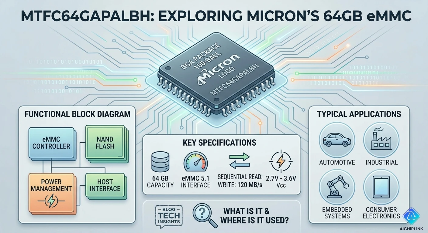
The MTFC64GAPALBH is Micron's answer to exactly that scenario: a 64GB, eMMC 5.1, industrial-grade managed NAND in a 153-ball TFBGA package, specified for −40°C to +85°C, built around MLC NAND with Micron's own controller, and listed in Micron's industrial product line alongside its automotive siblings. It is not the lowest-cost 64GB eMMC available. It is the one you specify when the device cannot be touched after deployment.
This guide decodes the part number, walks through every parameter that matters for industrial design, covers the hardware pitfalls that cause most eMMC failures in embedded Linux products, and tells you exactly when to pick this part over cheaper alternatives — and when cheaper is fine.
1.0 Part Number Decoded
Micron's eMMC part numbers encode density, interface version, package, and grade. Here is every field in MTFC64GAPALBH:
MT — Micron Technology manufacturer prefix
FC — Managed NAND (Flash, Controller) product category
64G — 64 GB capacity
A — eMMC version designation (this generation maps to eMMC 5.1)
P — Performance tier / NAND type (MLC NAND)
A — Revision/silicon generation
L — Package subtype
B — Package variant (153-ball TFBGA, 11.5 mm × 13 mm)
H — Height: 1.1 mm package height
Ordering suffix (appended after the base part number):
| Suffix | Grade | Temp Range | Notes |
|---|---|---|---|
| -IT | Industrial | −40°C to +85°C | Standard industrial; tray packaging |
| -IT TR | Industrial | −40°C to +85°C | Tape-and-reel packaging |
| -AIT | Automotive Industrial | −40°C to +85°C | Automotive qualified, extended screening |
| -AAT | Automotive | −40°C to +105°C | Full automotive, AEC-Q100 Grade 3 |
The base part number MTFC64GAPALBH is always qualified with one of these suffixes in ordering. MTFC64GAPALBH without a suffix is not a valid order code. The most common variant in industrial embedded Linux designs is MTFC64GAPALBH-IT (industrial, tray) or MTFC64GAPALBH-IT TR (industrial, tape-and-reel for SMT lines).
Note on package marking: Due to the small package size, Micron does not print the full part number on the BGA body. The device carries a 5-character abbreviated mark that cross-references to the full part number at micron.com/decoder. Always verify received parts by running the abbreviated mark through this decoder before use in production.
2.0 Specs at a Glance
All parameters from the Micron industrial eMMC datasheet (MTFC8GAM/16GAP/32GAP/64GAP/128GAP, Rev. D):
- Capacity: 64 GB (user data area; excludes boot partitions and RPMB)
- NAND Type: MLC (Multi-Level Cell), 2 bits per cell
- Interface Standard: JEDEC eMMC 5.1 (JESD84-B51)
- Host Interface: MMC protocol, x8 data bus (DAT0–DAT7)
- Speed Modes (supported): HS400 (max), HS200, HS52 (DDR52), HS26, legacy modes
- Max Sequential Read: ~300 MB/s (HS400, x8, typical)
- Max Sequential Write: ~100–150 MB/s (HS400, x8, cache on, typical)
- Command Queuing: Yes — up to 32 commands queued (eMMC 5.1 CQ)
- VCC (NAND supply): 2.7 V – 3.6 V (nominal 3.3 V)
- VCCQ (controller/I/O supply): 1.70 V – 1.95 V (nominal 1.8 V) or 2.70 V – 3.60 V
- VDDIM (internal voltage node): Requires 0.1 µF minimum, 1 µF recommended to GND — do not connect to VCC or GND directly
- Operating Temperature: −40°C to +85°C (industrial -IT grade)
- Package: 153-ball TFBGA, 11.5 mm × 13 mm × 1.1 mm, 0.5 mm ball pitch
- Boot Partitions: 2 × 4 MB (configurable; stores bootloader, pre-boot code)
- RPMB Partition: Replay Protected Memory Block for secure key storage (512 KB)
- Enhanced Strobe: Supported in HS400 (improves DQS strobe reliability at 200 MHz)
- ClearCACHE: Micron proprietary technology — forces cache flush before power removal
- Hardware Reset: Supported via RST_n pin
- Power-Off Notification (BKOPS): Supported — allows host to signal impending power loss
- Field Firmware Update (FFU): Supported — enables in-field controller firmware upgrade
- Secure Erase / Secure Trim: Supported
- AES Hardware Encryption: 128-bit / 256-bit (optional, requires host key management)
- P/E Endurance (MLC): Typically 3,000 P/E cycles per cell (managed by internal wear leveling)
- Data Retention: 1 year at 40°C after reaching rated endurance
- RoHS / Halogen-Free: Yes
3.0 How eMMC 5.1 Actually Works (The Details That Affect Your Design)
The dual power domain architecture:
Unlike SPI flash (single VCC), eMMC has two separate power domains that must be managed correctly:
VCC (2.7–3.6 V): Powers the NAND flash array itself — the most power-hungry part of the device. During sequential writes at full speed, VCC current can reach 200–400 mA in transient bursts. The VCC supply must deliver these transients without drooping below 2.7 V.
VCCQ (1.8 V or 3.3 V): Powers the eMMC controller core and the I/O interface signals. At HS400 speeds (200 MHz DDR), the I/O switching current is significant. Most modern SoCs with eMMC host controllers expect VCCQ = 1.8 V.
VDDIM: A third pin, unique to Micron eMMC devices, labeled "internal voltage node." This pin is neither a supply input nor a ground — it is a node of Micron's internal power management circuit that requires an external capacitor (minimum 0.1 µF, recommended 1 µF) connected to GND. It must not be connected to VCC, VCCQ, or GND directly — only the capacitor. Missing this capacitor or connecting VDDIM incorrectly causes unpredictable device behavior and is one of the most common bringup failures on new eMMC PCB designs.
HS400 mode — what it means for PCB layout:
HS400 uses an 8-bit DDR data bus at 200 MHz clock, plus a Strobe signal (DS) that the eMMC generates to strobe data back to the host. This combination achieves up to 400 MB/s theoretical bandwidth. At 200 MHz DDR, signal integrity requirements are demanding: controlled impedance traces (typically 50 Ω single-ended), maximum 75–100 mm trace length from SoC to eMMC, ±5% impedance tolerance, and careful attention to vias.
Enhanced Strobe in HS400 mode improves the timing margin of the DQS strobe signal at these frequencies. If your SoC host controller supports Enhanced Strobe (most modern controllers do), enable it — it significantly reduces read CRC errors in high-temperature deployments.
ClearCACHE — Micron's power-loss protection mechanism:
eMMC 5.1 includes a write cache — data written by the host is buffered in a volatile SRAM cache in the controller before being programmed to NAND. This dramatically improves write performance (buffered writes to SRAM are fast; NAND programming happens in the background) but creates a data loss risk: if power is removed while the cache contains unflushed data, that data is lost permanently.
Micron's ClearCACHE technology uses an internal energy source (a combination of internal capacitors and circuit design) to complete the in-progress NAND program cycle for cache-resident data when power is removed — similar in concept to the power-loss protection found in enterprise SSDs but implemented at the eMMC level. The effectiveness of ClearCACHE depends on the size of the buffered write and the available internal energy; for large write operations, the host must use the eMMC's Power-Off Notification (BKOPS/PON) mechanism to give the device time to flush the cache before power is removed.
Command Queuing:
eMMC 5.1 command queuing (CQ) allows the host to submit up to 32 read/write operations to the device simultaneously. The eMMC controller internally reorders these operations for optimal NAND access — similar to a disk queue scheduler. On random-access workloads (database writes, log files, frequent small writes), CQ can improve throughput by 2–3× compared to strictly sequential command submission. Enable CQ in your Linux mmc-utils configuration and in the kernel's MMC driver for best performance on workload-intensive industrial applications.
4.0 ⚠️ Five Pitfalls That Kill eMMC Deployments
Pitfall 1: Missing or wrong VDDIM capacitor
The VDDIM pin on the MTFC64GAPALBH is Micron-specific and not present on eMMC devices from Samsung or SK Hynix. Engineers copying a reference design from a Samsung eMMC (which has no VDDIM pin) to a Micron layout sometimes leave VDDIM unconnected or pull it to GND. The result: the device powers up and initializes correctly but exhibits intermittent failures under write load or temperature stress — typically manifesting as CRC errors or spontaneous resets. The fix: place a 1 µF X5R ceramic capacitor from VDDIM to VSS, within 3 mm of the VDDIM ball. This capacitor is non-optional.
Pitfall 2: VCC voltage sag during write bursts causes read-only remounts
The NAND programming current during large sequential writes can peak at 300–400 mA on VCC. If the PCB's 3.3 V supply rail has high impedance (thin traces, under-rated LDO, inadequate bulk capacitance), VCC can sag below 2.7 V during these bursts. The eMMC controller detects the under-voltage, aborts the write, and marks the affected block as bad. After several such events, the device exhausts its spare area and the controller forces a read-only lock. The failure looks like filesystem corruption but is actually a supply design problem. Fix: provide at least 100 µF bulk capacitance on the VCC supply, use a VRM or LDO rated for at least 600 mA, and keep VCC trace resistance below 50 mΩ from the power source to the eMMC VCC balls.
Pitfall 3: No Power-Off Notification in the host design
On a system with an uncontrolled power-off (industrial power supply failing, brownout, emergency shutdown), the eMMC cache may contain data that has not yet been written to NAND. Without Power-Off Notification (PON), the eMMC has no warning — it loses power mid-write, the NAND block is partially programmed, and the data is corrupted. With PON (an active-low signal on the RST_n pin or a software command via the eMMC's CMD0 interface), the device can complete or abort the in-progress operation safely. On designs where the power-off sequence is controlled by software (graceful shutdown from a supervisory MCU or watchdog), always implement PON. On designs with truly uncontrolled power loss, use a hold-up capacitor on VCC (typically 100–470 µF) to extend power long enough for the eMMC to complete or flush its cache operation (~5–10 ms).
Pitfall 4: Specifying the -IT grade for a design that operates above 85°C
The MTFC64GAPALBH-IT is rated for −40°C to +85°C. Many industrial enclosures exceed 85°C internal ambient temperature when operating near heat sources or in inadequately ventilated enclosures. eMMC operating above the rated junction temperature exhibits increased data retention errors (NAND cells lose charge faster at high temperature), elevated bit error rates, and accelerated wear. At 95°C continuous operation, an -IT grade eMMC may fail within months. If your application's worst-case junction temperature exceeds 85°C, you need either the MTFC64GAPALBH-AAT (automotive grade, −40°C to +105°C) or a redesign to improve thermal management. The two variants are pin-compatible.
Pitfall 5: Using the eMMC's user area for direct high-frequency writes without wear leveling
The MLC NAND inside the MTFC64GAPALBH is rated for approximately 3,000 P/E cycles. The internal FTL (Flash Translation Layer) performs wear leveling across the entire user area — but only for data written through the standard MMC interface. Applications that write directly to fixed logical block addresses (LBAs) — for example, a log file that always appends to the same file, or a configuration register updated every second — concentrate writes on a small set of physical blocks. Even with FTL wear leveling, pathological write patterns can exhaust a small set of cells faster than the average predicts.
Calculate your TBW (Terabytes Written) budget: for a 64GB MLC eMMC at 3,000 P/E cycles, the theoretical TBW = 64 GB × 3,000 = 192 TB. With a Write Amplification Factor (WAF) of 2 (typical for mixed workloads with good alignment): effective TBW ≈ 96 TB. At 10 GB/day of writes, that is 26 years. At 100 GB/day, it is 2.6 years. Know your write rate before committing to MLC — if you genuinely need 100+ GB/day sustained for 5+ years, look at Micron's pSLC variants or external NVMe storage.
5.0 PCB and System Design Notes
Package and footprint: TFBGA-153, 11.5 mm × 13 mm body, 0.5 mm ball pitch, 1.1 mm height. This is the standard eMMC 153-ball footprint shared across Micron, Samsung (KLMAG series), SK Hynix (H26M series), and Kioxia eMMC families. PCB land pattern: 0.35 mm circular pad, 0.5 mm center-to-center, designed for 4-layer minimum PCB (6-layer preferred for HS400).
Power decoupling — mandatory values:
| Supply | Recommended Bulk | Per-ball Bypass | Placement |
|---|---|---|---|
| VCC (3.3 V) | 100 µF (electrolytic or polymer) | 100 nF X5R ceramic per VCC ball | Within 5 mm of VCC balls |
| VCCQ (1.8 V) | 47 µF | 100 nF X5R per VCCQ ball | Within 5 mm |
| VDDIM | N/A | 1 µF X5R, directly to VSS | Within 3 mm of VDDIM ball |
VCC and VCCQ power-up sequencing: VCC and VCCQ may power up simultaneously or with VCC first. VCCQ must never be applied before VCC. The host controller's MMC driver must assert RST_n (hardware reset) low for at least 1 µs after both supplies are stable, then deassert RST_n and wait 200 µs before issuing CMD0 (GO_IDLE_STATE). Violation of this sequence causes the eMMC controller to boot into an undefined state, typically appearing as a CMD_TIMEOUT on the first MMC command.
HS400 signal routing rules:
- Trace impedance: 50 Ω (±10%) for CLK, CMD, DAT0–DAT7, DS
- Maximum trace length: 75 mm (SoC to eMMC); shorter is always better
- CLK and DS must be routed on the same PCB layer if possible; length-match CLK to within ±3 mm
- All DAT0–DAT7 traces length-matched to ±5 mm of each other
- No 90° bends; use 45° or curved routing on all high-speed signal lines
- VSS reference plane immediately below the high-speed signal layer
RST_n pin: If the host SoC does not implement hardware MMC reset, connect RST_n to a GPIO or to the system reset signal. Do not leave RST_n floating — an undefined RST_n state can prevent the eMMC from initializing correctly after power-up.
6.0 Comparison: When This Part Is Right, When It Is Not
| Parameter | MTFC64GAPALBH-IT (Micron) | Samsung KLMAG2JENB | SK Hynix H26M64103EMR | Kioxia THGBMDG9D1LBAIL |
|---|---|---|---|---|
| Capacity | 64 GB | 64 GB | 64 GB | 64 GB |
| eMMC Standard | 5.1 | 5.1 | 5.1 | 5.1 |
| NAND Type | MLC | MLC | MLC | MLC |
| Temp Grade | −40°C to +85°C | −40°C to +85°C | −40°C to +85°C | −25°C to +85°C |
| Package | TFBGA-153 | TFBGA-153 | TFBGA-153 | TFBGA-153 |
| VDDIM pin | Yes — requires 1 µF cap | No | No | No |
| Power-loss protect | ClearCACHE | Partial write abort | Partial write abort | Controller-dependent |
| FFU support | Yes | Yes | Yes | Yes |
| CQ support | Yes | Yes | Yes | Yes |
| Automotive grade | -AAT available | KLMAG2JENB-B031 | H26M64103EMR-A | THGBMDG9D1LBAIL-A |
| Typical seq read | ~300 MB/s | ~300 MB/s | ~290 MB/s | ~300 MB/s |
| Relative pricing | Reference | +5–10% | −5–10% | −5–10% |
Choose MTFC64GAPALBH-IT when:
- Design requires −40°C to +85°C industrial grade with Micron's lifecycle commitment
- Micron is the preferred or sole-source supplier for your supply chain
- The system's power-off behavior is uncontrolled and ClearCACHE provides additional protection over competing implementations
- Your SoC reference design was validated against Micron eMMC (common in designs based on i.MX8, RK3399, AM62x reference kits)
Do NOT choose MTFC64GAPALBH-IT when:
- The application operates above 85°C junction temperature — use the -AAT (automotive, 105°C) variant instead
- The system is strictly cost-optimized consumer electronics with controlled power-off — cheaper consumer eMMC is appropriate
- You need AEC-Q100 automotive qualification — the -IT grade is not automotive qualified; use -AAT or -AIT
- High-frequency write workloads exceed the TBW budget of MLC NAND — evaluate pSLC or Micron's TLC-based MTFC64GASAQHD-IT with pSLC emulation
7.0 Sourcing Authentic MTFC64GAPALBH
Authorized channels: Micron Technology does not sell direct to most embedded design teams. Authorized distribution channels include Mouser Electronics, DigiKey, Arrow Electronics, Avnet, and Future Electronics. All carry MTFC64GAPALBH-IT in both tray and tape-and-reel packaging.
Lifecycle status: Check Micron's product page before procurement. Some MTFC64GAPALBH variants have moved to "Not Recommended for New Designs" (NRND) status as Micron refreshes its industrial eMMC lineup. If the -IT variant shows NRND, the -AIT (automotive industrial) is typically the available replacement — pin-compatible, same electrical behavior, broader qualification.
Counterfeit detection: Verify received parts against Micron's FBGA Part Marking Decoder at micron.com. The 5-character abbreviated mark on the BGA surface maps to the full part number. Any discrepancy indicates a counterfeit or substituted part. Also verify the lot code and date code against the purchase order; eMMC lot traceability is standard from Micron's factory and should flow through to the distributor's certificate of conformance.
Minimum order quantity: 1 tray (typically 75–100 units per tray at most distributors). Tape-and-reel MOQ is typically 500–1,000 units.
For verified authentic Micron MTFC64GAPALBH-IT and related Micron eMMC inventory with competitive pricing and full traceability, visit aichiplink.com.
8.0 Real Questions from Embedded Linux Engineers
Q: My MTFC64GAPALBH-IT fails to initialize on power-up about 10% of the time. The kernel reports "mmc0: error -110 whilst initialising MMC card." The same design works fine with our Samsung eMMC. What is different?
A: The most likely cause is either the VDDIM capacitor or the power-up timing sequence. First, verify the VDDIM pin has a 1 µF ceramic capacitor to VSS — if this is missing or connects to VCC/GND directly, initialization is unreliable. Second, check the VCC/VCCQ ramp time and the RST_n assertion sequence. The Micron eMMC requires RST_n to be asserted (low) during power-up and held for at least 1 µs after VCC and VCCQ reach their operating range before being deasserted. Many eMMC host controller drivers assume a specific ramp time; check your device tree's mmc-pwrseq-simple configuration for the reset-gpios and timing delays. Samsung eMMC has wider initialization timing margin, which is why the same design works with Samsung but fails with Micron — the Micron part is within specification, but the design is marginal.
Q: How do I check the health/wear status of a deployed MTFC64GAPALBH-IT in the field?
A: Use mmc-utils on Linux (install via apt-get install mmc-utils or build from source). The key command is:
mmc extcsd read /dev/mmcblk0
The extended CSD register contains several health indicators: PRE_EOL_INFO (pre-end-of-life information, values 0x01=Normal, 0x02=Warning (consumed 80% of estimated life), 0x03=Urgent) and DEVICE_LIFE_TIME_EST_TYP_A/B (estimated device life used for A and B memory types, in 10% increments). For automated field monitoring, parse these fields in your device health check service and alert when PRE_EOL_INFO reaches 0x02. Do not wait for 0x03 — by that point, replacement should already be in progress.
Q: We are using MTFC64GAPALBH-IT in a Yocto-based embedded Linux system. What kernel configuration ensures HS400 and CQ are actually enabled?
A: Verify the following in your kernel config and device tree. In menuconfig: enable CONFIG_MMC_SDHCI (or the specific host controller driver for your SoC), CONFIG_MMC_BLOCK, and CONFIG_MMC_BLOCK_BOUNCE. For HS400, ensure the host controller driver includes HS400 support (most modern SoC drivers do by default). In the device tree node for your MMC controller, set max-frequency = <200000000> (200 MHz for HS400) and include mmc-hs400-1_8v if your VCCQ is 1.8 V. For Command Queuing, add supports-cqe; to the host controller DTS node. After booting, verify HS400 mode is active: cat /sys/kernel/debug/mmc0/ios should show timing spec: hs400. Verify CQ with cat /sys/bus/mmc/devices/mmc0\:0001/cqe_enable — should return 1.
Q: The -IT and -AIT versions have the same temperature range (−40°C to +85°C). Why would I pay more for -AIT?
A: The -AIT (Automotive Industrial) variant undergoes additional qualification testing beyond the -IT industrial grade: expanded electrical screening at the wafer and package level, enhanced thermal cycling test duration (more cycles, tighter pass criteria), stricter lot traceability documentation aligned with automotive supply chain requirements, and qualification to portions of AEC-Q100 (though full Grade 3 certification at −40°C to +85°C requires the -AAT). For industrial applications in markets where automotive-level supply chain traceability is required — medical device manufacturing, railway, defense — the -AIT provides documentation that the -IT cannot. For standard industrial IoT and embedded Linux applications without supply chain certification requirements, the -IT is adequate and costs less.
9.0 Quick Reference Card
Part Number Suffix Decoder:
| Suffix | Grade | Temp | Automotive QA | Use For |
|---|---|---|---|---|
| -IT | Industrial | −40° to +85°C | No | Standard industrial embedded Linux |
| -IT TR | Industrial | −40° to +85°C | No | Same, tape-and-reel for SMT lines |
| -AIT | Auto Industrial | −40° to +85°C | Partial | Supply-chain-certified industrial |
| -AAT | Automotive | −40° to +105°C | AEC-Q100 Gr.3 | Automotive, high-temp industrial |
Critical VDDIM Rule:
Connect a 1 µF X5R ceramic capacitor from VDDIM to VSS within 3 mm of the VDDIM ball.
Do NOT connect VDDIM to VCC or GND directly. Missing this capacitor causes intermittent failures.
Power-Up Sequence:
- Apply VCC (3.3 V) and VCCQ (1.8 V) — simultaneous or VCC first
- Hold RST_n LOW during power ramp
- After VCC/VCCQ stable → hold RST_n LOW for ≥ 1 µs
- Assert RST_n HIGH (deassert reset)
- Wait ≥ 200 µs
- Issue CMD0 (GO_IDLE_STATE)
Linux Health Check Commands:
# Read extended CSD (health, wear status)
mmc extcsd read /dev/mmcblk0

# Key fields to monitor:
# PRE_EOL_INFO: 01=Normal, 02=Warning (80% life), 03=Urgent
# DEVICE_LIFE_TIME_EST_TYP_A: life used, in 10% increments
# DEVICE_LIFE_TIME_EST_TYP_B: same for second memory type

# Verify HS400 is active
cat /sys/kernel/debug/mmc0/ios | grep timing

# Verify Command Queuing is enabled
cat /sys/bus/mmc/devices/mmc0:0001/cqe_enable
TBW Estimate (MLC, 3,000 P/E cycles, WAF=2):
| Daily Write Rate | Estimated Life |
|---|---|
| 1 GB/day | >260 years |
| 10 GB/day | 26 years |
| 100 GB/day | 2.6 years |
| 500 GB/day | ~6 months |
At 500 GB/day write rates, consider pSLC variants or external NVMe.
For sourcing Micron MTFC64GAPALBH-IT and related industrial eMMC with verified authenticity and competitive pricing, visit aichiplink.com.

Written by Jack Elliott from AIChipLink.
AIChipLink, one of the fastest-growing global independent electronic components distributors in the world, offers millions of products from thousands of manufacturers, and many of our in-stock parts is available to ship same day.
We mainly source and distribute integrated circuit (IC) products of brands such as Broadcom, Microchip, Texas Instruments, Infineon, NXP, Analog Devices, Qualcomm, Intel, etc., which are widely used in communication & network, telecom, industrial control, new energy and automotive electronics.
Empowered by AI, Linked to the Future. Get started on AIChipLink.com and submit your RFQ online today!
Frequently Asked Questions
What is MTFC64GAPALBH used for?
MTFC64GAPALBH is a 64GB industrial-grade eMMC 5.1 storage device used in embedded Linux systems, industrial gateways, IoT devices, and edge computing equipment requiring high reliability and wide temperature support.
Is MTFC64GAPALBH suitable for high-temperature environments?
Yes. The -IT variant supports −40°C to +85°C, while the -AAT automotive version supports up to +105°C, making it ideal for harsh industrial and automotive applications.
What makes Micron Technology eMMC different from consumer eMMC?
Micron industrial eMMC offers MLC NAND, better endurance, power-loss protection (ClearCACHE), and extended temperature range, unlike consumer eMMC designed for light workloads and standard temperatures.
How long does MTFC64GAPALBH eMMC last?
With ~3,000 P/E cycles, a 64GB device has an estimated ~96TB effective write endurance (with WAF≈2). Lifespan depends on daily write volume—about 2–26 years in typical industrial workloads.
What is the most common design mistake with MTFC64GAPALBH?
The biggest issue is incorrect handling of the VDDIM pin. It requires a 1 µF capacitor to ground—missing or misconnecting it causes instability, initialization failure, or data errors.


.png&w=256&q=75)


