The Equipment Passed EMC Testing in the Lab. It Failed in the Field. Here Is Why.
The test setup for CE marking was clean. The shielded cables were grounded at one end, per the standard recommendation. The equipment sailed through conducted emissions testing. Six months later, the first field installation was in a factory — long cable runs between a PLC and sensors, 20 meters across a concrete floor, different power distribution panels at each end. Within a week, the operator reported erratic sensor readings and intermittent communication errors. The equipment had not changed. The grounding had not changed, technically. But the ground potential difference between the two panels was 800 mV at 50 Hz, and a single-ended grounded cable shield in this environment acts like a receiving antenna for exactly that frequency.
This scenario plays out in industrial facilities, audio installations, medical equipment rooms, and data centers worldwide. The rules about cable shield grounding are not wrong — they are just not complete. Single-ended grounding is not universally correct; both-end grounding is not universally wrong; and the correct approach depends on the frequency of the interference, the length of the cable relative to the wavelength, and the ground potential difference between the cable endpoints. Understanding these three variables gives you a systematic way to specify shielding and grounding that survives installation conditions the lab never tested.
1.0 Prerequisites: What You Need to Know Before You Ground Anything
Before deciding how to ground a cable shield, you need to characterize the problem. Guessing the grounding method without this information is why the same cable installation works in one facility and fails in another.
Identify the dominant interference frequency.
The entire logic of shield grounding changes at approximately 100 kHz. Below this threshold, the primary threat is electric-field coupling from power lines (50/60 Hz) and low-frequency magnetic fields. Above 100 kHz, radiation and capacitive coupling from digital signals dominate. Above 1 MHz, skin effect becomes significant — interference currents begin to flow on the outer surface of the shield rather than through the bulk conductor, which changes how the shield should be terminated.
Practical method: measure the noise on the signal line with a current probe on the cable shield and an oscilloscope. Note the dominant frequency. If you see 50/60 Hz hum, the problem is low-frequency electric field coupling. If you see ringing at tens or hundreds of MHz, the problem is high-frequency radiation.
Determine whether the cable is electrically short or electrically long.
A cable is electrically short when its physical length is less than λ/20 at the highest interference frequency of concern. Above λ/20, the cable cannot be treated as a lumped element — distributed effects matter and simple single-point grounding becomes increasingly inadequate.
Example: At 1 MHz, λ = 300 m, λ/20 = 15 m. A 5-meter cable is electrically short at 1 MHz. A 30-meter cable is electrically long. At 100 MHz, λ/20 = 1.5 m — almost any cable of practical length becomes electrically long.
Measure the ground potential difference between cable endpoints.
With a floating-input voltmeter or differential probe, measure the AC voltage between the chassis ground points at each end of the proposed cable run. A difference above 50 mV at 50/60 Hz is sufficient to drive significant noise current through a shield grounded at both ends. This measurement is the most commonly skipped step and the most reliably useful diagnostic.
Know your shield type — it affects termination requirements.
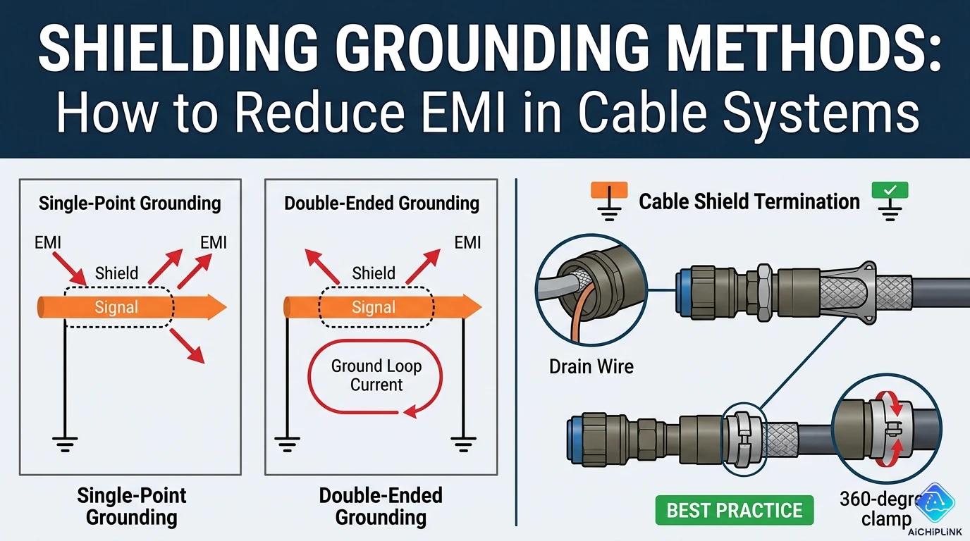
Foil shield (aluminized polyester): High coverage percentage (~100%), good high-frequency performance, fragile under flexing. Terminated via drain wire. The drain wire runs along the inside of the foil, in contact with the conductive side. The drain wire is the connection point — never the foil itself, which tears easily.
Braided shield: Lower coverage (typically 85–98%) but mechanically robust and lower DC resistance. Better low-frequency magnetic shielding effectiveness than foil. Terminated by folding back over a connector ferrule (360° termination) or via pigtail for lower-performance applications.
Combined foil-plus-braid: Provides both high-frequency (foil) and mechanical durability (braid). Preferred for industrial environments.
2.0 Step-by-Step: Choosing and Implementing the Right Grounding Method
Step 1 — Select the grounding method based on frequency and cable length
Single-point grounding (one end only):
Use when: signal frequencies are below 100 kHz, cable is electrically short (< λ/20 at the interference frequency), AND the ground potential difference between endpoints is significant (> 50 mV).
Ground at the source end for most applications — the end nearest the signal driver or power supply, which is the voltage reference for the signal. For sensors driving long cables into a receiving instrument, ground at the sensor end (source).
Single-point grounding prevents 50/60 Hz ground loop current from flowing through the shield. The shield capacitively intercepts electric-field interference from power lines; because it has no complete circuit path to ground at the remote end, no loop current flows.
Both-end grounding (multipoint):
Use when: frequency of concern is above 100 kHz, cable is electrically long (≥ λ/20), or skin effect has reduced the coupling between outer-surface currents and inner-surface signal currents (above approximately 1 MHz for copper braid).
At high frequencies, the skin effect means that noise currents on the shield's outer surface return via the outer surface back to ground through the chassis — they do not couple into the inner conductor as they would at low frequency. Grounding both ends gives these high-frequency currents a complete low-impedance return path at both cable terminations.
Practical concern: if grounding both ends creates a ground loop at 50/60 Hz (visible as hum or low-frequency noise on the signal), use the hybrid method below.
Hybrid grounding (one end direct, other end through capacitor):
Use when: the cable must handle both low-frequency (audio, 50 Hz hum environments) and high-frequency (RF, digital) interference simultaneously, or when both-end direct grounding causes ground loop problems.
Connect the shield directly to chassis at one end. At the other end, connect the shield to chassis through a low-inductance ceramic capacitor — typically 0.01 µF to 0.1 µF, X7R or C0G dielectric — as close to the connector as physically possible.
The capacitor's DC and low-frequency impedance is high: at 50 Hz, 0.01 µF presents Z = 1/(2π × 50 × 0.01×10⁻⁶) ≈ 318 kΩ — effectively an open circuit that prevents 50 Hz ground loop current. At 10 MHz, the same capacitor presents Z = 1/(2π × 10×10⁶ × 0.01×10⁻⁶) ≈ 1.6 Ω — a low-impedance high-frequency ground path. This hybrid approach gives you single-point grounding behavior at power-line frequencies and both-end grounding behavior at high frequencies, from a single connection.
Step 2 — Connect the shield to chassis, not to circuit ground
This distinction is critical and widely ignored. The cable shield should connect to the metal chassis or equipment enclosure, not to the signal ground or circuit common of the PCB inside.
When the shield is connected to circuit ground, any RF current on the shield (from external radiation or from the cable acting as an antenna) has a direct path into the circuit ground reference, where it can mix with signal currents and cause interference. When the shield is connected to the chassis, those RF currents flow on the outside surface of the chassis and return to earth through the chassis's capacitive coupling to the environment — never entering the signal circuit.
Practical implementation: at the equipment enclosure, connect the cable's shield (via the connector shell or a dedicated ground lug) to the metal enclosure wall or backplane, not to the PCB's GND pin. Only then connect the chassis to circuit ground at a single, carefully chosen point if they are not already bonded.
Step 3 — Terminate with 360° contact, not a pigtail
A pigtail is a length of the drain wire or braided shield folded back and connected via a wire to the ground point. At low frequencies (< 100 kHz), a pigtail connection works adequately. At high frequencies, the pigtail inductance is a serious problem.
A 25 mm (1 inch) pigtail wire has an inductance of approximately 25 nH. At 100 MHz: Z_L = 2π × 100×10⁶ × 25×10⁻⁹ ≈ 15.7 Ω — substantial series impedance that defeats the low-impedance ground connection required for effective high-frequency shielding.
A 360° connection — where the entire circumference of the braid is in contact with the connector shell or a conductive clamp — has essentially zero inductance at the connection point. Use 360° termination for any application where the interference frequency exceeds approximately 10 MHz.
Practical method for 360° termination: strip the outer jacket, fold the braid back over a conductive ferrule or connector shell, and crimp or clamp the braid around the entire circumference. EMC-optimized connectors (MIL-DTL-38999, DE-9 with metallic shell and proper backshell, circular metal connectors) are designed for this. Plastic-shell connectors cannot provide 360° termination.
Step 4 — Add ferrite chokes for high-frequency common-mode suppression
Shield grounding is not the only tool available. Ferrite chokes clipped or threaded onto cables suppress common-mode current — the asymmetric current that flows in the same direction on all conductors including the shield, which is the primary mechanism by which cables radiate EMI.
For maximum effectiveness at a specific frequency range, select ferrite material (commonly type 31 for 1–300 MHz, type 43 for 25–300 MHz) matched to the frequency of concern. Thread the cable through the toroid multiple times (4–5 passes through a toroid core increases impedance by the square of the number of turns: 5 turns = 25× impedance increase vs 1 turn). Snap-on ferrite clamps are less effective than through-wound toroids but are practical for post-installation noise suppression.
Place ferrites at the cable entry into the equipment enclosure, which is where common-mode currents are induced — not in the middle of the cable run.
3.0 Verification: How to Confirm the Grounding Is Actually Working
Test 1 — Continuity of the shield connection (< 1 Ω):
With the cable disconnected from both equipment ends, use a multimeter to verify continuity from the shield at one end to the chassis ground at the grounded end. The measurement should read below 1 Ω, ideally below 0.5 Ω. A high reading indicates a poor connection, corroded contact, or damaged drain wire.
Test 2 — Current probe measurement on the shield:
With the system powered and running, clip a current probe around the cable shield and measure with an oscilloscope. The shield current (at 50/60 Hz and at the operating frequencies of connected equipment) should be near zero for a properly implemented single-point ground. If you see significant 50/60 Hz current, a ground loop exists. If you see high-frequency current, there is a radiation path that the shield grounding has not adequately addressed.
Test 3 — Floating the remote end (diagnostic):
If the system is exhibiting noise and you suspect a ground loop, temporarily disconnect the shield from the remote end ground. If the noise decreases, the problem is a low-frequency ground loop — confirming single-point or hybrid grounding is needed. If the noise increases (which can happen with high-frequency interference), you have a high-frequency radiation problem — the shield needs both-end grounding.
Test 4 — Differential probe measurement:
For signal cables, compare the signal quality (noise floor, peak-to-peak noise) with a high-impedance differential probe before and after shield grounding changes. This gives a quantitative measurement of shielding effectiveness rather than a qualitative impression.
4.0 Troubleshooting Decision Tree
Symptom: 50/60 Hz hum on analog signal, audible as buzz in audio systems or visible as slow oscillation in sensor readings → Almost always a ground loop. Check: is the shield grounded at both ends? If yes, remove the ground from one end (usually the remote/load end). Confirm ground potential difference between cable endpoints. If > 50 mV, use hybrid grounding (capacitor at remote end). If problem persists, check that the shield is connected to chassis, not circuit ground.
Symptom: High-frequency noise on digital signals, CRC errors, data corruption on long RS-485 or CAN runs → Likely inadequate high-frequency shield termination. Check: are shields terminated with 360° connection or pigtail? Replace pigtail terminations with 360° connections. Verify both ends are grounded. Add ferrite chokes at cable entry points. Check cable routing (parallel runs with power cables?).
Symptom: Noise appears only when a nearby motor or VFD is running → VFDs generate high-frequency common-mode currents that conduct through ground and radiate from their output cables. Ensure signal cable shield is grounded at both ends (VFD noise is high-frequency). Separate signal cables and VFD output cables by at least 300 mm (avoid parallel runs). Route signal cables perpendicular to power cables at crossings. Add ferrite common-mode chokes on signal cables at the PLC/controller entry point.
Symptom: Equipment passed conducted EMC testing in the lab but fails in the field → Lab test environment had a single ground reference; field installation has multiple ground references with potential differences. Review the cable lengths and the ground topology in the field installation. Map the ground potential differences between all cable endpoint chassis. Reassess single-point vs. both-end grounding for each cable based on actual field conditions and interference frequencies.
Symptom: Shielded cable provides no improvement over unshielded cable → Shield is floating (no ground connection), shield is connected via long pigtail (defeating high-frequency performance), or the interference is magnetic (low-frequency magnetic fields are not blocked by typical cable shields — only by high-permeability mu-metal shields or by reducing the receiver loop area through twisted-pair geometry).
5.0 ⚠️ Six Mistakes That Turn a Shield Into an Antenna
Mistake 1: Assuming "one end only" is always the right answer
"Ground the shield at one end only" is the most commonly repeated rule in cable EMC guidance, and it is appropriate for low-frequency applications with long cable runs where ground potential differences exist. Applied blindly to high-frequency digital cable in a clean single-reference ground environment, it leaves the remote end of the shield floating, which causes it to act as a receiving antenna for high-frequency radiation. Match the grounding method to the frequency, not to the rule you remember from the last application.
Mistake 2: Using a long pigtail for the shield connection
Any length of drain wire used as a pigtail from the shield to the ground point adds inductance to the shield termination. The rule of thumb: keep pigtail length below 25 mm (1 inch) for applications up to 10 MHz. Above 10 MHz, eliminate the pigtail entirely and use a 360° connector-shell termination. A 50 mm pigtail at 100 MHz has approximately 50 Ω of inductive impedance — completely defeating the low-impedance ground connection needed for effective shielding.
Mistake 3: Connecting the shield to circuit ground instead of chassis
As described in Section 2, connecting the shield to the PCB's circuit ground creates a direct path for RF currents to enter the signal reference. The shield should be an extension of the metal enclosure, terminating to the chassis. The chassis is then bonded to circuit ground at one controlled point. This distinction is not academic — it makes a measurable difference in high-frequency EMC performance.
Mistake 4: Routing signal cables parallel to power cables
The best cable shield and grounding in the world cannot overcome coupling from an adjacent high-current power cable running parallel at close distance. The magnetic field from a parallel power cable induces voltage in the signal cable loop proportional to the loop area and the coupling length. Separate signal cables from power cables by at least 300 mm in open trays. Where crossing is unavoidable, cross at 90° (perpendicular) to minimize the coupling length. Ferrite chokes on signal cables at the entry to the equipment enclosure provide the last line of defense.
Mistake 5: Floating the shield entirely because "grounding causes loops"
An ungrounded shield capacitively couples interference from the environment onto the signal conductors through the shield-to-conductor capacitance, then re-radiates it. A floating shield offers no effective protection and can make the situation worse than no shield at all. Even a single-point ground is substantially better than floating. The goal is to choose the single-point or both-end termination appropriately — not to avoid grounding the shield.
Mistake 6: Mixing shield grounding connections between cables
When multiple shielded cables interconnect the same equipment, inconsistent grounding strategies (some single-ended, some both-ended, some floating) create complex current flow patterns that are difficult to diagnose. Adopt a consistent strategy for all cables within a given system based on the dominant frequency: all low-frequency control cables single-ended grounded at the controller, all high-frequency data cables both-ended with 360° termination.
6.0 Real Questions from Engineers in the Field
Q: I have a 15-meter RS-485 cable in a factory with VFDs on the same cable tray. The cable already has a foil shield with drain wire. Should I ground at both ends or one end?
A: Both ends, with 360° termination at the controller panel entry. RS-485 is a differential balanced signal that inherently rejects common-mode noise, but VFDs generate high-frequency (kHz to MHz range) common-mode currents that couple strongly onto cable shields. At these frequencies, both-end grounding with the lowest possible impedance connection is essential. Ground the shield at the PLC cabinet entry by connecting the drain wire and foil to the cabinet chassis — not to the PLC's signal ground. At the remote sensor/device end, ground to the local panel chassis. Additionally, add a ferrite common-mode choke (type 31 or 43 material, wound 3–5 turns) at the PLC panel entry on the RS-485 cable to suppress any remaining common-mode energy. If you still see noise, increase the separation from VFD output cables to at least 300 mm.
Q: My audio installation (XLR balanced microphone cables, 20 meters) has 50 Hz hum from the stage to the mixing desk. The cable shields are grounded at the mixing desk end (standard practice). Why is there still hum?
A: Several possibilities, in order of likelihood. First, verify the shield is not accidentally making ground contact at the stage end — check the connector shells. Second, check that the XLR pin 1 (shield/ground) connects to the connector chassis/shell at both the source (microphone) and the load (desk) end, not to pin 1 of the balanced input on the PCB inside the desk (the "pin 1 problem" described by Neil Muncy). Connecting shield/chassis currents to PCB pin 1 creates a common-impedance coupling path. Third, measure the ground potential difference between the stage and the mixing desk. If it exceeds 100 mV at 50 Hz, you have a building ground integrity problem that no cable shielding will fully solve — consider using a signal isolation transformer (DI box) between the microphone and the long cable run.
Q: Is there a practical way to implement hybrid grounding if the connector doesn't have a separate shield-ground terminal?
A: Yes. At the remote end, solder the drain wire (or fold back the braid) to a small PCB or terminal strip mounted inside the enclosure, then connect a 0.047 µF or 0.1 µF X7R ceramic capacitor from this point to the chassis ground. Keep the capacitor leads as short as possible — mount the capacitor directly at the point where the drain wire connects, within 10 mm of the cable entry. For retrofit situations where the connector is already installed, a ferrite bead in series with the drain wire (before a direct ground connection) also provides partial high-impedance blocking for low-frequency currents while passing high-frequency ones — though a capacitor is more effective.
7.0 Quick Reference Card
Grounding Method Selection — Decision at a Glance:
| Situation | Method | Reason |
|---|---|---|
| < 100 kHz, long cable, ground potential diff. present | Single-point (source end) | Prevents 50/60 Hz ground loop |
| > 1 MHz, or electrically long cable (> λ/20) | Both ends, 360° termination | Skin effect; low-impedance HF path |
| Mixed frequencies, or both-end causes low-f hum | Hybrid (direct + capacitor) | Blocks LF loop, passes HF to ground |
| VFD/motor drive environment | Both ends + ferrite chokes | HF common-mode suppression |
| Unknown — first attempt | Single-point, then test | Safest starting point; add if needed |
The Frequency Boundary:
| Frequency | Grounding rule | Physics reason |
|---|---|---|
| < 100 kHz | Single-point preferred | Ground loop current degrades LF SNR |
| 100 kHz – 1 MHz | Hybrid recommended | Transition zone; both issues present |
| > 1 MHz | Both-end required | Skin effect; pigtail inductance critical |
Termination Quality — Effect on Impedance at 100 MHz:
| Termination type | Approximate impedance at 100 MHz |
|---|---|
| 360° connector-shell bond | < 0.1 Ω |
| 10 mm pigtail | ~10 Ω |
| 25 mm pigtail | ~16 Ω |
| 50 mm pigtail | ~31 Ω |
Shield Connection: Always chassis, never circuit ground at the cable entry point.
Ferrite selection:
- Type 31: best 1 MHz – 300 MHz
- Type 43: best 25 MHz – 300 MHz
- Wind 4–5 turns through a toroid for maximum effect
- Place at equipment enclosure cable entry, not mid-cable
Troubleshooting shortcuts:
- 50/60 Hz hum → ground loop → try single-point or hybrid
- Data errors on long RS-485/CAN → VFD/HF noise → both-end + ferrites
- Shield no better than no shield → shield is floating OR pigtail too long OR magnetic field (shielding won't help, use twisted pair)
- Passed lab, failed in field → ground potential difference in installation → measure GND diff, reassess method
For sourcing shielded cable, ferrite chokes, and EMI suppression components, visit aichiplink.com.

Written by Jack Elliott from AIChipLink.
AIChipLink, one of the fastest-growing global independent electronic components distributors in the world, offers millions of products from thousands of manufacturers, and many of our in-stock parts is available to ship same day.
We mainly source and distribute integrated circuit (IC) products of brands such as Broadcom, Microchip, Texas Instruments, Infineon, NXP, Analog Devices, Qualcomm, Intel, etc., which are widely used in communication & network, telecom, industrial control, new energy and automotive electronics.
Empowered by AI, Linked to the Future. Get started on AIChipLink and submit your RFQ online today!
Frequently Asked Questions
Why did equipment pass EMC testing but fail in the field?
Because lab environments typically have a single, clean ground reference, while real-world installations often have ground potential differences between endpoints. These differences can create unintended current paths in cable shields, turning them into noise receivers instead of protectors.
Should cable shields be grounded at one end or both ends?
It depends on frequency and conditions. Single-end grounding is best for low-frequency interference and when ground potential differences exist, while both-end grounding is required for high-frequency noise. A hybrid method (one end direct, one end via capacitor) works best for mixed environments.
Why is connecting the shield to chassis ground important?
Connecting the shield to the chassis prevents high-frequency noise currents from entering the circuit ground. If connected to signal ground instead, noise can couple directly into sensitive electronics and degrade performance.
What is the problem with using a pigtail for shield grounding?
Pigtails introduce inductance, which significantly increases impedance at high frequencies. This weakens shielding effectiveness, making the cable vulnerable to RF interference. A 360° termination is much more effective.
How can you fix EMI issues in industrial environments with motors or VFDs?
Use both-end grounding with proper 360° termination, add ferrite chokes at cable entry points, and physically separate signal cables from power cables. These steps reduce high-frequency common-mode noise and improve signal integrity.