What is an Inductor? Exploring Types and Applications

Think of a flywheel on a bike. It resists sudden changes in speed. What is an inductor? It does the same for electric current. This passive electronic component stores energy in a magnetic field when current flows through it. So, what is an inductor? It is a simple coil of wire, often wrapped around a core. You might also hear it called a choke or reactor. The coil creates a magnetic field that opposes any quick change in current. This behavior makes the inductor useful in many circuits. Understanding this part helps you see how electronics control energy flow.
Key Takeaways
-
An inductor slows down quick changes in electric current, working like a flywheel that keeps the flow steady.
-
Pick the right core material: air works for high frequencies, ferrite works for power circuits, and iron works for low frequencies.
-
Inductors store energy in magnetic fields. This allows buck converters to reach 85-95% efficiency.
-
An inductor's impedance goes up as frequency rises, so it works great for low-pass filters and noise chokes.
-
Going above the current rating causes core saturation, which makes the inductance drop sharply.
What Is an Inductor? Basics and Function
What Is an Inductor and How Does It Work?
You might ask how an inductor works at its most basic level. The answer is based on a simple idea. When current flows through a wire, it makes a magnetic field around the wire. Wind the wire into a coil, and the magnetic field becomes tighter. This makes the effect stronger. Now you have an inductor.
The inductor stores energy in this magnetic field. The energy stays stored while current flows. When you try to change the current, the inductor pushes back. This happens because of Lenz's law.
An induced voltage creates a current that makes a magnetic field which opposes the original magnetic field.
The self-induced voltage fights any change in current. When you first turn on a circuit, the growing magnetic field creates a back voltage. This back voltage slows down the current increase. The inductor resists quick current changes this way.
The time constant in an RL circuit decides how quickly current rises. You find this time constant by dividing inductance by resistance. After one time constant, current reaches about 63.2% of its final value. The circuit settles after five time constants, when current reaches 99.3% of the steady value. Without this slow rise, fast magnetic field changes would cause arcing and harm parts.
Key Characteristics: Inductance, Current Rating, and Core
Three main features define how an inductor works. First, inductance measures how much energy the inductor can store. You state inductance in henries (H). Higher inductance means more energy can be stored.
Second, current rating tells the highest current the inductor can handle. This rating links directly to core saturation. When current goes above the saturation point, inductance drops a lot.
Third, the core material changes how the inductor acts at different frequencies. Ferrite cores have high permeability and low energy loss at high frequencies. They saturate quickly, so you must keep them in the linear range. Powder iron cores saturate slowly, which gives a safety margin for high-current uses. Sendust and composite cores balance high saturation with heat stability. Nanocrystalline cores work for low-noise power uses.
The energy stored in an inductor follows a simple rule. Stored energy equals one-half times inductance times current squared. This formula shows that energy grows with the square of current. Doubling the current makes stored energy four times bigger. For example, an inductor with 0.5 H inductance and 3.2 A current stores 2.56 J. This amount is within the normal operating range for such parts.
Temperature changes how saturation works. Ferrite materials have higher saturation flux density at high temperatures. But initial permeability goes down, which lowers inductance before saturation. Powder cores keep steadier features across temperature ranges. For car or factory designs, check saturation current at the highest working temperature. Ferrite-core inductors above 85°C may need a 10–20% reduction in rating.
Knowing how an inductor stores energy helps you design better circuits. The same idea works for big systems. Superconducting magnetic energy storage uses coils with no resistance. These systems store megajoules for power grid uses. MRI solenoids and particle accelerator magnets use the same physics. What is an inductor? It is a basic energy storage device. How does an inductor act in advanced systems? It helps power supplies and medical imaging work.
Types of Inductors
Core-Based Types: Air Core, Iron Core, Ferrite Core
You can sort most inductor types by what material sits inside the coil. The core decides how much inductance you get and how the part acts at high frequency.
| Core Type | High-Frequency Relevance |
|---|---|
| Air core | Works best in high-frequency settings |
| Iron core (ferrite core) | Great performance in high-frequency applications |
| Ceramic core | Made for high-frequency applications |
Air-core inductors have no magnetic core, so they lose less energy and have fewer unwanted effects at very high frequencies. They are often custom-made for specific RF circuits, but you rarely see them in mass-produced SMT formats because they are larger.
Saturation also tells these types apart. An air-core inductor never saturates, so its inductance stays steady and linear at all operating currents. An iron-core inductor saturates when all magnetic domains line up under high current, and its inductance drops sharply to near the air-core value. A ferrite-core inductor also saturates under high current.
However, iron-core inductors can store energy in the magnetic field, which may add slight losses in clarity, especially at higher frequencies. For this reason, they usually work best for low-frequency uses, often below about 200–300 Hz.
Specialized Inductor Designs
Toroidal inductors use a closed-ring core. This symmetrical design keeps the magnetic field inside the core, which greatly lowers electromagnetic interference compared to solenoid types. Their carefully wound wire structure sharply cuts stray fields, so nearby circuits stay safe.
Chip inductors work for compact boards. A Coilcraft 0402 series part covers about 18 nH to 120 nH, with values like 18 nH, 39 nH, and 75 nH and a typical tolerance near ±10%.
Thin-film inductors reach higher precision than wire-wound inductors. TDK states that thin-film parts come from precise deposition methods similar to semiconductor manufacturing, which gives steady inductance values and excellent high-frequency response. Wire-wound inductors wrap copper wire around a magnetic core, a method valued for high current capacity and durability.
Inductor in a Circuit: Behavior and Formulas
Impedance and Phase Relationship in AC Circuits
When you put an inductor in a circuit, it acts differently for AC and DC. For DC, the inductor works like a wire after the current starts flowing. For AC, the inductor slows down the current because of its inductive reactance. This opposition is called inductive reactance. You can find it with the formula X_L = 2πfL, where f is frequency in hertz and L is inductance in henries. The unit for reactance is ohms.
Reactance changes with frequency. Think about a 1 mH inductor. At 50 Hz, its reactance is only 0.31 ohms. At 1 MHz, the same inductor has 6.28 k ohms of reactance. This big jump shows how much frequency matters. For a 10 mH inductance, reactance goes from 3.14 ohms to 62.8 k ohms. For 100 mH inductance, it goes from 31.4 ohms to 628 k ohms. Even a small 10 µH inductance has 0.003 ohms at 50 Hz and 62.8 ohms at 1 MHz. You must think about this change when making circuits.
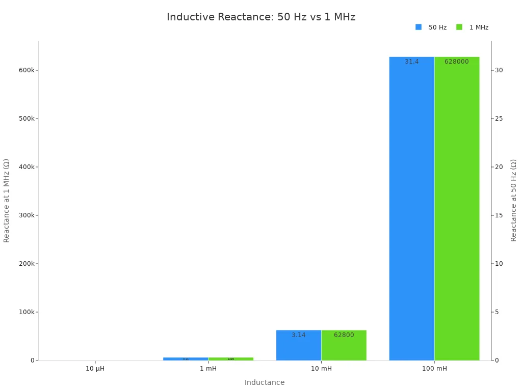
The phase relationship between voltage and current is important. In a pure inductor, voltage leads current by 90 degrees. This phase shift explains why inductors store energy in magnetic fields and let it go later. Inductive reactance is not the same as resistance. It changes with frequency.
But you also have to think about self-resonant frequency (SRF). Every inductor has small unwanted capacitance between its turns. At SRF, this capacitance cancels the inductance. The impedance reaches its highest peak. Above SRF, the part acts like a capacitor. Impedance goes down as frequency goes up. Running above SRF causes filtering and matching problems. The golden rule: pick inductors where SRF is at least 10 times the working frequency. This stops failures in RF circuits.
Key formulas control how inductors act in circuits. The terminal definition v = L di/dt links voltage to how fast current changes. This sets voltage rating and current slope. The flux-based definition L = NΦ/I connects inductance to flux linkage. The core geometry formula L = N^2 Ae μ / le gives design choices: turns, core area, path length, and permeability. Stored energy W = 1/2 L I^2 drives core size choices. The differential inductance L_diff = dΦ/dI * N is important for AC behavior around a DC bias. You must use the measured inductance value at the real operating point for correct design.
| Formula | Description | Design Implication |
|---|---|---|
| v = L di/dt | Terminal definition linking voltage to current rate of change | Determines voltage rating and current slope |
| L = NΦ/I | Flux-based definition relating inductance to flux linkage | Useful for magnetic circuit analysis |
| L = N²Aeμ/le | Inductance from core geometry and permeability | Key design knobs: turns, area, path length, permeability |
| W = ½ L I² | Stored magnetic energy | Drives core size and gapping decisions |
| L_diff = dΦ/dI · N | Differential inductance from flux-current curve | Use actual operating current for accurate design |
Series and Parallel Inductor Combinations
When you put inductors in series, total inductance adds up directly. For two inductors, L_total = L1 + L2. But mutual inductance can change this. If magnetic fields help each other, total is L1 + L2 + 2M. If fields work against each other, you subtract 2M. Coupling factor k sets how strong M is. Designers often put inductors far apart to reduce coupling.
For parallel connection, you have to use the reciprocal formula. The total inductance is the inverse of the sum of inverses.
1 / L_total = 1 / L1 + 1 / L2 + 1 / L3 + ...
This formula works only when no magnetic coupling is present. With coupling, the total inductance can change by 15 to 30 percent. You must check mutual inductance in tight layouts.
Tolerance matters in real parts. Inductor tolerance for smaller values like 1 µH is plus or minus 10 percent. For larger values of 33 µH or more, tolerance tightens to plus or minus 5 percent. Manufacturing tolerance on inductance is usually 10 to 20 percent. Temperature changes can shift specs by plus or minus 15 percent. Always use measured inductance values at working conditions. Combine inductors to get specific values, but think about these changes.
Knowing these behavior patterns helps you use an inductor in a circuit well. You can predict impedance, pick working frequency, and combine parts with confidence.
Applications of Inductors
Power Supply Filters and Energy Storage
You use an inductor in switching power supplies like a buck converter. The part stores energy in a magnetic field when the switch turns on. Current rises in a straight line during this on-time. When the switch turns off, the field collapses and the coil gives energy to the load. This cycle repeats at high frequency, which keeps the output current smooth.
| Regulator Type | Typical Efficiency | Notes |
|---|---|---|
| Buck Converter (with power inductor) | 85–95% | Handles large voltage drops efficiently, reduces heat, extends battery life |
| Linear Regulator (LDO) | η = Vout / Vin | Efficiency limited by the ratio of output to input voltage |
A buck converter with a power inductor is much more efficient than a linear regulator. The part stores and moves energy without burning it as heat. You see this benefit in battery-powered devices where power is limited.
An inductor also works in low-pass filters to clean up noise on a DC line. A second-order LC filter combines a coil with a capacitor.
A second-order low-pass filter improves attenuation performance by increasing the rolloff to −40 dB per decade.
This steep roll-off removes high-frequency ripple much better than a capacitor alone can.
RF Circuits, Transformers, and Chokes
You use an inductor in RF circuits to make resonant tank circuits. It pairs with a capacitor to pick one frequency and reject others. This tuning action is key for radios and wireless transmitters. The part makes a magnetic field that couples with nearby coils in a transformer. Two or more coils on a shared core move energy through mutual inductance. This lets you step voltages up or down for power distribution.
A choke is a coil that blocks high-frequency AC while passing DC. You place it on power lines to stop noise from entering sensitive circuits. Its impedance goes up with frequency, so it chokes off unwanted signals. Common-mode chokes have two windings on a single core. They block common-mode noise while letting differential signals pass. This keeps the field balanced and lowers radiated interference.
An inductor is a basic passive electronic part. It stores energy in a magnetic field and blocks fast current changes. Air cores work well at high frequencies, iron cores work below a few hundred hertz, and ferrite cores handle high-frequency power well. Nanocrystalline cores now help with EV charging and renewable energy systems. Think of a capacitor: it stores energy in an electric field, while an inductor stores it magnetically. Try building a low-pass filter or a buck converter to watch these parts work. You will see why the inductor is still vital in modern electronics.

Written by Jack Elliott from AIChipLink.
AIChipLink, one of the fastest-growing global independent electronic components distributors in the world, offers millions of products from thousands of manufacturers, and many of our in-stock parts is available to ship same day.
We mainly source and distribute integrated circuit (IC) products of brands such as Broadcom, Microchip, Texas Instruments, Infineon, NXP, Analog Devices, Qualcomm, Intel, etc., which are widely used in communication & network, telecom, industrial control, new energy and automotive electronics.
Empowered by AI, Linked to the Future. Get started on AIChipLink and submit your RFQ online today!
Frequently Asked Questions
What limits the maximum operating frequency of an inductor?
Each inductor has a small amount of capacitance inside it, between its turns. At the self-resonant frequency (SRF), this capacitance cancels out the inductance. Above the SRF, the part works like a capacitor. You should choose inductors where the SRF is at least 10 times your working frequency.
Why does exceeding the current rating affect performance?
Going over the current rating causes core saturation. Inductance falls sharply toward the air-core value. Ferrite cores saturate quickly. Powder iron cores saturate slowly, which gives a safety margin for high-current designs. For temperatures above 85°C, you may need a 10–20% rating reduction.
Can you combine inductors to get a specific value?
Yes. Inductors in series add directly: L₁ + L₂. Parallel connection uses the reciprocal formula. Mutual magnetic coupling changes the result by 15–30 percent. Always use measured values at your working conditions. Manufacturing tolerance typically runs 10–20 percent.
What makes a buck converter so efficient?
The inductor stores energy in its magnetic field while the switch is on. It releases that energy when the switch turns off. This process moves power without burning it as heat. A buck converter reaches 85–95% efficiency, much higher than a linear regulator.