What is a Silicon Controlled Rectifier (SCR)?
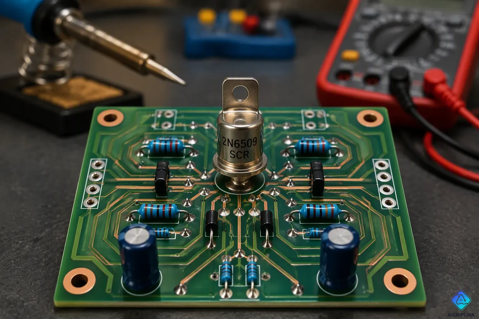
A silicon controlled rectifier is a four-layer solid-state device that lets current flow in one direction. Think of it as a Shockley diode with an extra gate terminal. Many engineers call this part a thyristor. Picture a one-way gate that stays locked until a signal opens it. After it opens, the gate stays open by itself. That is how an SCR acts. You will learn how this SCR works, its main features, and where people use it. A good thyristor tutorial starts with these basics. The device has three terminals: anode, cathode, and gate. It handles power switching in many circuits.
Key Takeaways
-
An SCR is a switch made from four layers of semiconductor, with three terminals: anode, cathode, and gate.
-
A small gate current turns on the SCR, and it stays on even after the gate signal is gone.
-
The SCR lets current flow in just one direction and stops it from going backward.
-
SCRs control power in dimmers, motor drives, and power supplies.
-
SCRs can control a lot of power, but they switch at lower speeds than transistors.
What Is a Silicon Controlled Rectifier?
A silicon controlled rectifier belongs to the thyristor family of semiconductor devices. You can view it as a four-layer power semiconductor device that regulates current flow in one direction. This component contains three terminals and performs switching and rectification tasks in power electronics. The core structure uses four alternating layers of p-type and n-type semiconductor material arranged as PNPN. This layered design separates it from standard diodes and transistors. This thyristor tutorial gives you the essential facts you need.
Four-Layer PNPN Structure
The key to this device lies in its four-layer PNPN structure. These alternating p-type and n-type layers create three junctions labeled J1, J2, and J3. The first layer is p-type material connected to the anode. The second layer is n-type material forming junction J1 with the first layer. Junction J2 forms between the first n-type layer and the second p-type layer. The third layer is p-type material connected to the gate terminal, located closer to the cathode. The fourth layer is n-type material connected to the cathode, with junction J3 forming between the second p-type layer and this n-type layer.
This configuration produces different blocking states. Forward blocking mode means junctions J1 and J3 are forward-biased while J2 is reverse-biased. Reverse blocking mode means J1 and J3 are reverse-biased while J2 is forward-biased. You can see how the SCR acts like a switch that blocks voltage in both directions but only conducts in one direction once triggered. This four-layer power semiconductor device gives you far more control than a simple diode.
The device shares its basic structure with the Shockley diode. A Shockley diode contains the same PNPN layers but only two terminals: anode and cathode. It has no gate terminal. The primary use of Shockley diodes was to control an SCR. An SCR uses the same structure as a Shockley diode but adds a gate connection to the p-type layer. An unconnected gate allows the device to function as a Shockley diode.
Anode, Cathode, and Gate Terminals
The silicon controlled rectifier has three distinct terminals. The anode connects to the outer p-type layer. The cathode connects to the outer n-type layer. The gate terminal connects to the inner p-type layer near the cathode.
The gate terminal controls turn-on behavior. You inject current into the gate to switch the device on. The SCR stays in the OFF state until the gate-to-cathode current exceeds a certain threshold. At that point, the device turns ON and conducts current. A small gate current starts a regenerative feedback process that latches the component into conduction. After this happens, you can remove the gate current entirely. The device stays ON as long as the anode current remains above the holding current. A pulse at the gate while the device current is below the latching current leaves the SCR in the OFF state.
This makes the SCR a current-operated device. A small gate current controls a much larger anode current. It conducts only when forward biased and a triggering current reaches the gate. It blocks current flow when reverse biased, regardless of gate current. Once triggered ON, it stays latched ON until the anode current drops.
You can also add an external gate-cathode resistor. This prevents false triggering from high dv/dt. The device turns ON when the gate terminal becomes positive with respect to the cathode. This causes gate current to flow. The device fires when the gate-cathode voltage reaches its threshold value.
How an SCR Switches On and Off
You now understand the structure and terminals of a silicon controlled rectifier. The next step is learning how this device actually turns on and off. This part of basic SCR operation follows a clear sequence. A small signal at the gate starts the process. The device then locks itself into conduction. Finally, the current level determines when it stops conducting.
Triggering the Gate
You trigger the SCR by applying a small current to the gate terminal. This gate current flows from the gate to the cathode. The gate trigger current, often called IGT, is the minimum current needed at the gate to start turn-on. For small devices, this value can be as low as 2 mA. High-power thyristors may require up to 150 mA. So the minimum gate trigger current for a standard SCR is 2 mA.
When you apply this gate current, a regenerative feedback process begins inside the four-layer structure. Electrons and holes start moving across the junctions. This movement creates more charge carriers. The process builds on itself rapidly. Within microseconds, the device switches from blocking voltage to conducting current. The anode-to-cathode path opens up. Current now flows freely from anode to cathode.
You control the exact moment of turn-on by timing your gate pulse. This gives you precise control over when the SCR starts conducting. A short pulse is often enough. The gate does not need continuous current to keep the device on. That brings us to the next key concept.
Latching and Holding Current
Once the SCR turns on, it latches into conduction. Latching means the device stays on even after you remove the gate signal. The internal feedback process sustains itself. You no longer need gate current to keep the anode-to-cathode path open. This is a defining feature of SCR operating modes.
The device remains on as long as the anode current stays above a certain level. This level is called the holding current. When the anode current drops below the holding current, the SCR turns off. The regenerative feedback stops. The device returns to its blocking state. You must then apply a new gate pulse to turn it on again.
Think of it like a door that locks behind you. You push it open with a small effort. The door stays open on its own. It only closes when you stop pushing against it entirely. The holding current works the same way for the SCR.
This latching behavior makes the SCR useful for power control. You can trigger it with a brief pulse. The device then handles large currents on its own. A thyristor tutorial often highlights this trait. It separates the SCR from simple switches that need constant control signals.
Understanding these two phases helps you design circuits that use the SCR effectively. You time your gate pulse to start conduction. You manage the anode current to stop it. This simple two-step process gives you reliable control over power flow.
Key Traits of the SCR
One-Way Conduction
The silicon controlled rectifier lets current flow in only one direction. Current goes from anode to cathode when you trigger it. It blocks current in the reverse direction no matter what you do at the gate. This one-way action gives the SCR its ability to rectify. You can change alternating current into direct current with this feature. The device works like a check valve for electricity. It lets flow go one way and stops it the other way.
This one-way flow affects all SCR operating modes. In forward blocking mode, the device holds back voltage until a gate pulse comes. In reverse blocking mode, it blocks voltage with no trigger. When conduction starts, the SCR has a small voltage drop across itself. That forward voltage drop is usually between 1.2V and 2.5V. The exact value depends on the device and the current level.
The forward voltage drop across an SCR during conduction is usually between 1.2V and 2.5V, based on the device specs and how it is used. Things like current size and junction temperature affect this range. This drop causes significant power loss in high-current uses.
High-Power Switching
The SCR easily handles large voltages and currents. A small gate pulse controls a much larger power flow. This makes the device a workhorse in power electronics. A thyristor tutorial often mentions this strength. The SCR switches fast enough for many industrial tasks. It turns on in microseconds after you apply gate current.
Switching speed varies among power devices. The table below shows where the SCR fits.
| Device | Switching Speed / Frequency | Notes |
|---|---|---|
| SCR (Thyristor) | ~50–60 Hz | Low frequency due to high power capability; highest current/voltage ratings. |
| GTO | <5 kHz | Limited operating frequency; poor turn-off characteristics. |
| Triac | ~50–60 Hz | Similar to thyristor; longer turn-off time. |
| MOSFET | Highest switching speeds | Superior for high-frequency applications; easy gate drive. |
| IGBT | Lower than MOSFET, higher than BJT | Combines MOSFET and BJT advantages; moderate switching speed. |
The basic idea is simple. Devices that can handle more power have lower frequencies. The SCR gives up speed for raw power handling. You get the highest current and voltage ratings of any power switch. That trade-off works well for line-frequency tasks like motor drives and power supplies.
Where Thyristors and SCRs Are Used
You will spot these devices in lots of places once you know what to look for. A thyristor tutorial often shows real-world examples first. The SCR works best in circuits that need exact power control. It also does well at changing and guarding power. Let's check out the two main jobs this device does.
Power Control Circuits
You can use an SCR to control how much power reaches a load. A light dimmer is a classic example. The circuit triggers the SCR at different points in each AC cycle. This action changes how much voltage the lamp gets. You turn the knob, and the light changes brightness. The same idea works for motor speed controls. An SCR adjusts the power sent to a motor. The motor then spins faster or slower based on your setting.
Power supplies also depend on these devices. You can steady output voltage by controlling when the SCR fires. This method works well for high-power equipment. Think about a welding machine or a large battery charger. Both need steady, adjustable power. The SCR gives that control with a small gate signal. You get reliable performance without complex drive circuits.
Rectification and Protection
The SCR turns alternating current into direct current. This process is called rectification. You trigger the device only during the positive half of the AC wave. Current flows in one direction through the load. The negative half gets blocked. You end up with a pulsing DC output. Many industrial power supplies use this method. You can also control the output voltage by adjusting the trigger timing.
Protection circuits use the SCR in a different way. A crowbar circuit is a good example. The circuit watches for an overvoltage condition. When the voltage gets too high, the SCR fires. It makes a short circuit across the power supply. This action blows a fuse or trips a breaker. The sensitive equipment downstream stays safe. You sacrifice a cheap fuse instead of an expensive device. This simple trick protects computers, radios, and other electronics from voltage spikes.
SCR vs. Diodes and Transistors
SCR vs. Diode
You already know a diode lets current flow one way. An SCR does the same job, but it adds a gate for control. A diode conducts the moment you forward-bias it. No trigger is needed. An SCR waits for a gate pulse before it conducts. This difference makes the diode an uncontrollable device. Its current flow depends only on the applied bias. The SCR is a semi-controllable device. You turn it on with a gate signal, but you cannot turn it off through the gate alone.
The on-state voltage drop also differs. A standard silicon diode drops about 0.7V to 1.2V. A Schottky diode drops as low as 0.3V to 0.5V. An SCR typically drops 1.0V to 1.8V. Some high-performance units stay below 1.5V. That higher drop means more heat. The SCR also uses a larger die, often 30% to 50% bigger. Its three-junction structure causes thermal cycling during switching. A diode runs cooler and more consistently. Still, the SCR wins when you need control. It can handle currents beyond 1000 amperes.
SCR vs. Transistor
A transistor and an SCR both switch current. The similarity ends there. A transistor needs continuous base or gate drive to stay on. An SCR latches on after a brief trigger. You remove the gate signal, and the device keeps conducting. This latching behavior simplifies your drive circuit. You fire one short pulse and walk away.
The SCR also beats bipolar junction transistors in high-power work. It turns on more easily. Its practical current density is much greater. Internal drive regeneration maximizes conductivity modulation. This lets the SCR carry high currents with low conduction loss. A transistor cannot match that efficiency at the same power level. So for line-frequency jobs like motor drives and rectifiers, the thyristor remains the practical choice. A transistor suits high-frequency switching instead.
You now know the silicon controlled rectifier as a triggered, latching, one-way switch. A small gate pulse starts the flow of current. The device then keeps itself on until the current drops below the holding level. This lets it control and change power in dimmers, motor drives, and power supplies. Look around your home and workshop. You will find these parts inside chargers, welding gear, and protection circuits. The market shows that staying power. Industry reports predict the selective catalytic reduction system market will reach $8.86 billion by 2029. It is growing at 9.0% each year. That growth shows how much modern power electronics still relies on this dependable four-layer switch.

Written by Jack Elliott from AIChipLink.
AIChipLink, one of the fastest-growing global independent electronic components distributors in the world, offers millions of products from thousands of manufacturers, and many of our in-stock parts is available to ship same day.
We mainly source and distribute integrated circuit (IC) products of brands such as Broadcom, Microchip, Texas Instruments, Infineon, NXP, Analog Devices, Qualcomm, Intel, etc., which are widely used in communication & network, telecom, industrial control, new energy and automotive electronics.
Empowered by AI, Linked to the Future. Get started on AIChipLink and submit your RFQ online today!
Frequently Asked Questions
What does SCR stand for?
SCR stands for silicon controlled rectifier. It is a four-layer PNPN semiconductor device with three terminals: anode, cathode, and gate. Engineers also call it a thyristor. You use it to switch and control current in one direction.
How do you turn off an scr?
You cannot turn it off through the gate. The device stops conducting only when the anode current drops below the holding current. At that point, the internal feedback stops. You must apply a new gate pulse to turn it on again.
Can an SCR work with alternating current?
Yes. The SCR conducts only during the positive half of the AC cycle when triggered. It blocks the negative half. This behavior lets you rectify AC into DC and control power in dimmers and motor drives.
What happens if you remove the gate signal after turn-on?
Nothing changes. The SCR latches into conduction and stays on. The gate only starts the process. The anode current keeps the device conducting until it falls below the holding level.