Monostable Circuit – Definition, Working Principle, and Applications
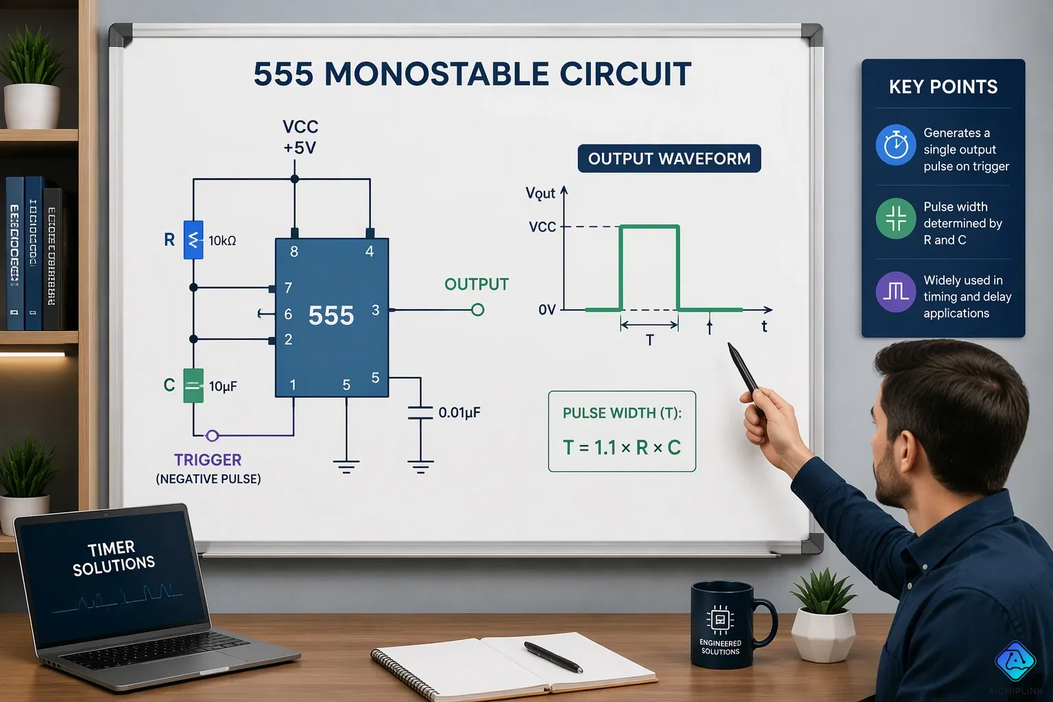
A monostable circuit, also called a one-shot circuit, is a multivibrator with one stable state and one unstable state. Its output is normally LOW, sitting in the stable condition. An external trigger pushes the circuit into its unstable state for a fixed period. Then, it returns to LOW automatically.
The pulse width depends on an external resistor and capacitor. You set the timing by choosing these two parts. This simple control makes the monostable circuit useful for timing and control jobs. You can create exact delays, clean up noisy signals, or make precise output pulses. The circuit handles these tasks with few parts. Knowing this one-shot behavior helps you build reliable timing solutions for your projects.
Key Takeaways
-
A monostable circuit gives out one set pulse each time it gets a trigger. After that, it goes back to its normal state.
-
The pulse width is found using the formula T = 1.1 × R × C, where R stands for resistance and C stands for capacitance.
-
You can make a one-shot timer using a 555 timer chip and only two extra parts: a resistor and a capacitor.
-
Monostable circuits help fix switch bounce, make clean pulses, and create exact delays.
-
The standard 555 timer one-shot is not retriggerable, so extra triggers during the timing period are ignored.
What Is a Monostable Circuit?
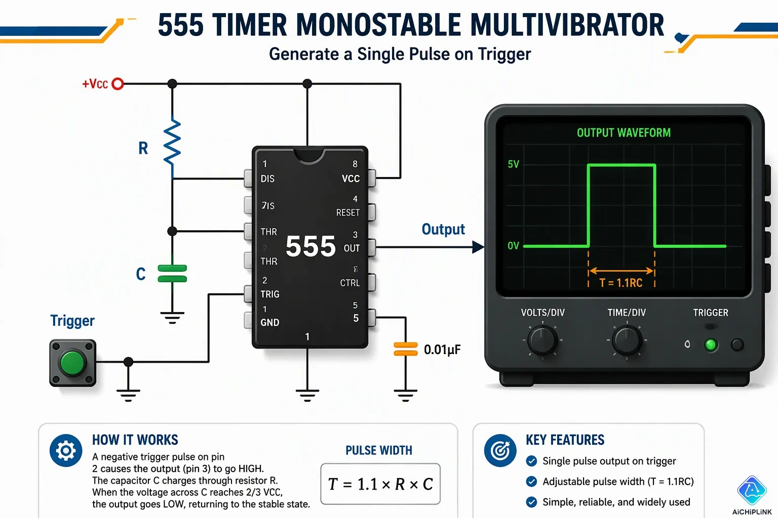
A monostable circuit sits quietly in its stable state until you wake it up. Think of it like a doorbell button. The doorbell stays silent until someone presses the button. Then it rings for a set time and goes quiet again. That behavior makes this circuit a one-shot timer. You trigger it once, and it produces exactly one output pulse.
One Stable State and One Unstable State
Every multivibrator family member behaves differently. An astable multivibrator has no stable state at all. It oscillates continuously, generating a square wave whose frequency depends on RC time constants. A bistable multivibrator holds two stable states. It maintains a given output indefinitely unless you apply an external trigger. It acts like a flip-flop or latch, requiring two separate trigger pulses to complete a full cycle.
Your monostable circuit sits between these two extremes. It has one stable state and one quasi-stable state. Without any external trigger signal, the circuit remains stably predefined, typically outputting a low level near 0V. This steady equilibrium persists indefinitely. The discharge transistor stays saturated, and the capacitor voltage rests at approximately zero.
| Feature | Monostable Multivibrator | Bistable Multivibrator |
|---|---|---|
| Stable States | One stable state (typically low level) | Two stable states (high or low level) |
| State Transition | Requires external trigger to enter quasi-stable state | Requires external trigger to switch between the two stable states |
| Output Behavior | Produces a fixed-width pulse upon triggering, then automatically returns to stable state | Remains indefinitely in either stable state until triggered; acts as a 1-bit memory (e.g., SR latch) |
Steady-state output: The output (Vout) is at a low level (0V). Without any external trigger signal, the circuit remains stably predefined, typically outputting a low level.
Triggering a Fixed Output Pulse
The trigger input starts the timing cycle without affecting the quiescent state. Here is how the sequence unfolds:
-
Trigger Initiation: A falling edge on the TRIG pin drops the voltage below one-third of Vcc. This action inverts the trigger comparator and sets the RS flip-flop. The output immediately drives high, and the discharge transistor turns off, starting the timing cycle.
-
Timing Process: The capacitor charges exponentially from 0V toward Vcc through resistor R. As long as the capacitor voltage stays below two-thirds of Vcc, the threshold comparator outputs a low signal and does not alter the flip-flop state. The output remains high. The pulse width depends solely on the RC time constant, which is the time needed to charge from 0V to two-thirds of Vcc.
-
Auto-Reset: When the capacitor voltage reaches two-thirds of Vcc, the threshold comparator toggles. It resets the flip-flop, and the output returns to its low quiescent state. The discharge transistor re-saturates, ending the transient.
The duration of the triggered state follows the formula t = 1.1 × R × C. You choose the resistor and capacitor values to set your desired pulse width. In a standard one-shot configuration, additional trigger pulses during the timing period do not restart the output pulse. The circuit ignores them until it completes its cycle and returns to the stable state.
This monostable circuit behavior gives you precise control over timing events. You can generate clean pulses, debounce mechanical switches, or create exact delays. The simplicity of one resistor and one capacitor makes this approach practical for countless timing applications.
Working Principle of a Monostable Circuit
A monostable circuit works on a basic idea: a capacitor charges through a resistor until it reaches a set voltage, then the circuit resets itself. You pick the resistor and capacitor values to control the timing. The whole process follows a clear, step-by-step sequence.
How the RC Network Sets the Pulse Width
When you send a trigger pulse, the timing cycle starts. A negative pulse at the TRIG pin drops the voltage below one-third of Vcc. This sets the internal flip-flop, makes the output go high, and turns off the discharge transistor. With the discharge path open, the capacitor starts charging from Vcc through the resistor.
The capacitor voltage rises in a curve according to the formula Vc = Vcc × (1 − e^(−t/RC)). While the capacitor voltage stays below two-thirds of Vcc, the threshold comparator sends out a low signal. This low signal does not change the flip-flop state, so the output stays high. The circuit holds this unstable state for the whole charging time.
Inside the 555 timer, an internal voltage divider sets the threshold comparator's reference at two-thirds of Vcc. When the capacitor voltage hits this threshold, the comparator toggles and sends out a high signal. This resets the flip-flop, making the output return to its stable low state. At the same time, the discharge transistor turns back on, quickly draining the capacitor to zero volts. The circuit goes back to its stable state and waits for the next trigger.
The output pulse length follows the equation tW = 1.1 × R × C, where tW is the pulse length, R is the resistance in ohms, and C is the capacitance in farads. This standard formula for the 555 timer monostable mode gives you the math you need for design. For example, a 10 kΩ resistor with a 100 µF capacitor makes a pulse width of 1.1 seconds.
Component quality directly affects timing accuracy. High-tolerance capacitors, especially electrolytic types with ±20% tolerance, and leakage current cause wrong output pulse widths. You should use 1% precision metal film resistors and capacitors with tighter tolerances, such as 5% film types. Temperature coefficients also matter. By picking components with low temperature coefficients, you keep thermal stability in the output pulse width.
Retrigger Behavior and Output Pulse Shape
The standard 555 timer monostable setup is not retriggerable. If a trigger pulse arrives before the timing capacitor has fully discharged, the output pulse length gets shorter. The circuit needs about the same time as the original output to finish its cycle. Extra trigger pulses during the timing period do not restart the output pulse. The circuit ignores them until it finishes its cycle and returns to the stable state.
This non-retriggerable behavior differs from a retriggerable one-shot design. You can build a retriggerable monostable circuit using two 555 timers. In that design, the first timer's discharge pin holds the timing capacitor, stopping it from reaching the two-thirds Vcc threshold. If trigger pulses arrive faster than the timing period, the output stays continuously high. This behavior extends the output pulse indefinitely.
You can see the output pulse shape on an oscilloscope to check that your circuit works right. Connect Channel 1 to the trigger signal source to catch the trigger event. Connect Channel 2 to the output pin of the 555 timer. Set the oscilloscope in Single Shot mode with a falling-edge trigger on Channel 1. Use the cursor measurement function to measure the actual output pulse width and compare it with your theoretical value.
The TRIG pin needs a low-level pulse with a length much shorter than the desired output pulse width. If the low pulse lasts too long, the output stays high throughout the entire low pulse period plus an extra timing period. This condition causes timing errors. An RC differentiator circuit can turn a long button-press pulse into a short spike to avoid this issue.
Building a One-Shot Circuit with a 555 Timer
You can build a working monostable circuit with the NE555 timer chip. This chip has the comparators, flip-flop, and discharge transistor built in. You just add two outside parts: one resistor and one capacitor.
555 Timer Pin Connections for One-Shot Mode
The 555 timer has eight pins, but you only need five for monostable mode. Each pin has its own job:
| Pin | Name | Direction | Function in Monostable Mode |
|---|---|---|---|
| 2 | Trigger | Input | Starts the timing cycle when voltage drops below 1/3 Vcc |
| 3 | Output | Output | Goes high (Vcc) during the timing cycle, low (0V) after it ends |
| 6 | Threshold | Input | Ends the timing cycle when voltage exceeds 2/3 Vcc |
| 7 | Discharge | Output | Open-collector transistor that discharges the timing capacitor when the cycle ends |
You also hook pin 4 (Reset) to Vcc and pin 8 (Vcc) to your positive supply. Pin 1 goes to ground.
The wiring steps follow a clear order:
-
Connect the trigger source to pin 2. A falling edge below 1/3 Vcc starts the timing cycle.
-
Connect resistor R between Vcc and pin 7. Connect capacitor C between pin 7 and ground.
-
Connect pin 6 directly to the junction of R and C. This lets the threshold comparator watch the capacitor voltage.
-
Take your output from pin 3. It drives high during the timing cycle and returns low when the cycle ends.
Calculating Pulse Width with T = 1.1 × R × C
The output pulse width follows the formula T = 1.1 × R × C. You measure R in ohms, C in farads, and T in seconds. This equation gives you the time from trigger to auto-reset.
The 1.1 factor comes from the internal comparator setpoint at 2/3 Vcc. The capacitor charges according to the curve (1 - exp(-t/T)). Solving 2/3 = (1 - exp(-t/T)) gives t = -ln(1/3)RC. The value -ln(1/3) equals 1.0986, which rounds to 1.1.
Component choice matters for accuracy. Use resistors from 1 kΩ to 10 MΩ. Below 1 kΩ, too much current flows through the discharge transistor. Above 10 MΩ, input bias currents cause timing errors. Choose capacitors from 1 nF to 470 µF. Ceramic capacitors can shift timing by 20-30 percent due to voltage dependence. Film capacitors offer better stability. Electrolytic capacitors suit long durations but have ±20 percent tolerance.
Practical examples help you plan. A 1 nF capacitor with a 91 kΩ resistor produces a 100 µs pulse. A 10 nF capacitor with the same resistor gives 1 ms. A 100 nF capacitor yields 10 ms. Adjust R or C proportionally to reach your target duration. This monostable circuit design gives you reliable timing control with minimal parts.
Practical Applications of One-Shot Circuits
Pulse Generation and Switch Debouncing
Mechanical switches bounce. When you press a button, the contacts make and break several times before settling. A digital input sees this as multiple rapid transitions. A monostable circuit cleans up this messy signal.
You connect the switch to the TRIG pin. A falling edge starts the timing cycle, even if the switch closure continues or bounces. The output goes high immediately and stays high for the fixed period set by your RC network. When the capacitor reaches two-thirds of Vcc, the output returns low. The result is one clean pulse with a width of approximately 1.1 times R times C. The duration of your original switch press does not affect the output.
You can see this same behavior in Minecraft redstone. A lever produces a sustained signal. A redstone monostable circuit converts that sustained signal into a short pulse. Players use this trick to activate doors, traps, or command blocks with a single quick trigger instead of holding the lever.
Delays, Frequency Division, and Control Systems
The output pulse rate depends on how often you trigger the circuit. The pulse width itself stays fixed by the RC timing network. This separation gives you two useful tools.
For delay applications, you trigger the circuit with an event signal. A sensor detects an object and starts the timing period. You can use this period for delayed activation or delayed shutdown. An automatic lavatory faucet works this way. Your hand triggers the sensor, and water flows for five seconds before shutting off automatically. A darkroom timer uses the same principle. You press a button, and the safety light stays on for your preset duration.
Frequency division works differently. You feed a periodic input signal into the trigger. Each input cycle produces exactly one output pulse. This divides the input frequency by a fixed factor.
Industrial environments benefit from noise cancellation. You set the timing period slightly longer than typical noise duration but shorter than a valid signal. Short noise pulses produce output pulses you can ignore. A long valid signal retriggers the circuit to produce continuous pulses, confirming genuine presence. This technique cleans up sensor signals in factories and communication lines.
Control systems use monostable circuits for timed outputs. You can trigger specific actions with precise timing. Energy-saving hallway lights use this approach. You press the button, and the light stays on for two minutes before switching off automatically.
A monostable circuit delivers one fixed output pulse for every trigger you send. It holds one stable state and one unstable state. The external resistor and capacitor set the pulse duration precisely. You control timing by choosing these two components.
The 555 timer in monostable mode gives you a simple build path. You connect five pins and add one resistor plus one capacitor. The formula T = 1.1 × R × C predicts your output width.
You can debounce mechanical switches, generate clean pulses, or create exact delays. Each application relies on the same one-shot behavior. Master this circuit, and you unlock reliable timing control for your projects.

Written by Jack Elliott from AIChipLink.
AIChipLink, one of the fastest-growing global independent electronic components distributors in the world, offers millions of products from thousands of manufacturers, and many of our in-stock parts is available to ship same day.
We mainly source and distribute integrated circuit (IC) products of brands such as Broadcom, Microchip, Texas Instruments, Infineon, NXP, Analog Devices, Qualcomm, Intel, etc., which are widely used in communication & network, telecom, industrial control, new energy and automotive electronics.
Empowered by AI, Linked to the Future. Get started on AIChipLink and submit your RFQ online today!
Frequently Asked Questions
What happens if you trigger the circuit again during the timing period?
The standard 555 timer one-shot ignores extra trigger pulses while the timing cycle runs. The output completes its full pulse width without restarting. You must wait until the circuit returns to its stable state before sending another trigger. This non-retriggerable behavior keeps your output predictable.
Can you change the pulse width after building the circuit?
Yes. You swap either the resistor or the capacitor to adjust the timing. Increasing the resistance or capacitance lengthens the output pulse. Decreasing either value shortens it. Use the formula T = 1.1 × R × C to calculate your new pulse width before making changes.
How does a monostable circuit differ from an astable circuit?
An astable circuit has no stable state. It oscillates continuously, producing a free-running square wave. A monostable circuit holds one stable state and waits for a trigger. It produces exactly one output pulse per trigger event. The astable runs forever; the monostable sleeps until you wake it.
Why does the timing formula use the constant 1.1?
The 1.1 factor comes from the capacitor charging curve. The threshold comparator trips at two-thirds of Vcc. Solving the charging equation for that voltage gives -ln(1/3), which equals 1.0986. Engineers round this to 1.1 for practical calculations. The constant stays the same for any resistor or capacitor values.
What supply voltage should you use for a 555 timer one-shot?
The 555 timer operates across a wide supply range, typically from 5V to 15V. Your choice depends on your load requirements and logic levels. Lower voltages reduce power consumption. Higher voltages provide stronger output drive. Check your specific 555 datasheet for the exact limits of your chip.