You can use the scr bt151 as a good switch in many power systems. This silicon-controlled rectifier is great for running motors, dimming lights, or controlling heaters. The scr bt151 can handle high voltages and strong currents. This makes it popular in places that need safe and good power control. Many people pick the scr bt151 for motor speed, lighting, and safety systems. The bt151 scr is special because it gives exact current and voltage control. You can find scr bt151 devices in cooktops, power tools, and chargers. Look at the Datasheet to see its ratings. Silicon controlled rectifiers like the scr bt151 are important in modern electronics.
Key Takeaways
-
The BT151 SCR works like a strong switch. It controls motors, lights, and heaters that use a lot of power.
-
It comes in a TO-220 package. This package helps it stay cool. It also fits well in many circuits. This makes it good for medium-power projects.
-
A small gate current can turn on the SCR. The SCR stays on until the current gets low. This lets you control things exactly without always sending signals.
-
Always look at the datasheet for voltage, current, and temperature limits. This helps you use it safely and correctly in your projects.
-
Make sure to use the right pin connections. Use a heat sink for high-current uses. This keeps the SCR and your circuit safe.
scr bt151 Overview
What is BT151 SCR?
The scr bt151 is a medium-power silicon-controlled rectifier. It works like a switch for both AC and DC loads. The scr bt151 has a four-layer PNPN structure inside. If you put a small current into the gate, the scr turns on. It stays on until the current drops below a set level. This latching feature is helpful in circuits. You do not need to keep the gate signal on to keep it working.
The bt151 scr comes in a TO-220 package. This package helps it lose heat and is easy to mount. You often see the scr bt151 in motor control, lighting dimmers, and heater circuits. It can handle up to 12A of current and up to 650V. The scr bt151 works well and is stable in many power systems.
When you look at the scr bt151 and other scr types, you see some differences:
-
The scr bt151 uses a small TO-220 package, but other scr types may use stud base, flat base, or press pack designs.
-
The scr bt151 is for medium power, but some scr can handle higher currents or voltages.
-
The scr bt151 has good heat control and is easy to mount, but bigger scr types may not.
-
The scr bt151 gives steady conduction and exact current control, so people like it for home and industrial projects.
Note: The scr bt151 is a silicon-controlled rectifier. It is part of the silicon controlled rectifiers family used for switching and control in electronics.
Key Features
The scr bt151 has many important features:
-
High surge current capability lets it handle sudden spikes without damage.
-
Low on-state voltage drop saves energy and makes less heat.
-
Sensitive gate means you can turn it on with a small current, which is good for low-power circuits.
-
High holding current keeps the scr on during small current changes.
-
High dv/dt capability helps stop false triggering from voltage spikes.
-
Strong build means the bt151 scr works well in tough places.
-
The TO-220 package helps it lose heat for medium-power uses.
Here is a quick look at the main specifications from top makers:
| Specification | Typical Value (BT151) |
|---|---|
| Average On-State Current | 7.5A |
| Maximum On-State Current | 12A |
| Peak Surge Current | 120A |
| Voltage Rating | 500V to 650V |
| Gate Trigger Voltage | Max 1.5V |
| Holding Current | Max 20mA |
| Operating Temperature Range | -40°C to 125°C |
| Package Type | TO-220 |
You can use the scr bt151 in many ways, like motor control, light dimmers, voltage regulation, and protection circuits. The bt151 scr is known for being reliable, handling strong currents, and fitting easily into your projects.
bt151 technical specifications
Datasheet Summary
The datasheet for the scr bt151 has all the key facts. It tells you what the device can do and its main limits. You should check these details before using the scr bt151 in your project. Here is a table with the most important numbers from the datasheet:
| Parameter | Value |
|---|---|
| Average On-State Current (IT(AV)) | 7.5 A |
| Maximum On-State Current (IT(RMS)) | 12 A |
| Peak Surge Current (ITSM) | 120 A |
| Repetitive Peak Off-State Voltage | 500 V to 650 V |
| Gate Trigger Voltage (VGT) | Max 1.5 V |
| Gate Trigger Current (IGT) | Max 15 mA |
| Holding Current (IH) | Max 20 mA |
| Operating Temperature Range | -40°C to 125°C |
| Storage Temperature Range | -40°C to 150°C |
| Package Type | TO-220 |
The datasheet also shows the scr bt151 meets tough world standards. Makers follow ISO 9001 for quality and ISO 14001 for the environment. They also meet IATF 16949 for cars and ISO 13485 for medical tools. This means the scr bt151 is safe and works well.
Electrical Ratings
You need to know the electrical ratings for the scr bt151. These ratings show how much current and voltage it can take. The datasheet says the highest on-state current is 12 A. The average on-state current is 7.5 A. The scr can take a peak surge current of 120 A for a short time. The repetitive peak off-state voltage is between 500 V and 650 V, based on the model.
The gate trigger current (IGT) is important. You only need a small current to turn on the scr bt151. The datasheet says the highest gate trigger current is 15 mA. The holding current (IH) is also low, with a top value of 20 mA. This means the scr stays on even with small currents.
| Parameter | Value |
|---|---|
| Gate Trigger Current (IGT) | Max 15 mA |
| Holding Current (IH) | Max 20 mA |
Always check the datasheet before you use the scr bt151 in your circuit. This helps you keep your project safe and avoid damage.
Tip: Always use the datasheet values when you design your circuit. This will help your scr bt151 work its best.
Thermal and Package Details
The scr bt151 uses a TO-220 package. This package helps the device get rid of heat fast. You can put the TO-220 package on a heat sink to keep the scr cool when it works hard. Good heat control lets the scr handle big currents without getting too hot.
The datasheet gives the working and storage temperature ranges. You can use the scr bt151 in places as cold as -40°C or as hot as 125°C. For storage, you can keep it at up to 150°C. Here is a table to help you remember these numbers:
| Parameter | Temperature Range |
|---|---|
| Working Contact Temperature | -40°C to 125°C |
| Storage Contact Temperature | -40°C to 150°C |
You do not need special steps to store the scr bt151. Just keep it in the right temperature range from the datasheet. This will help keep the device in good shape until you use it.
The bt151 technical specifications show the scr bt151 is strong and reliable for many power jobs. You can trust the datasheet to help you use the scr safely and well.
Footprint and Pin Configuration
When you use the BT151 SCR, you should know its footprint and pin setup. This helps you connect it the right way in your circuit. The BT151 SCR comes in a TO-220 package. This package is common for medium-power parts. You can easily put this package on a circuit board or a heat sink.
Pinout Diagram
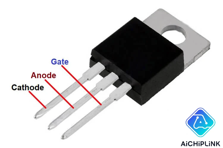
The BT151 SCR pinout uses a standard TO-220 layout. There are three main pins and a metal tab at the top. Each pin has its own job in the SCR. The table below shows how the pins are set up:
| Pin Number | Terminal Name | Description |
|---|---|---|
| 1 | Cathode | Conventional current flows out of the cathode |
| 2 | Anode | Conventional current flows into the anode |
| 3 | Gate | Controls conduction between anode and cathode |
| 4 | Tab | Electrically connected to the anode |
The first pin is the cathode. The second pin is the anode. The third pin is the gate. The metal tab at the top connects to the anode. This setup makes it simple to attach the SCR to a heat sink. The heat sink helps keep the SCR cool. When you look at the BT151 SCR pinout, always check the datasheet or the markings on the package. This helps you avoid mistakes.
Tip: Always check the pinout before you solder the SCR into your circuit. If you connect it wrong, you can break the device or your project.
Terminal Functions
Each terminal on the BT151 SCR does something special. You need to know what each one does to use the SCR safely.
-
Anode (Pin 2 and Tab): This is where current goes in. If you put a positive voltage on the anode and a negative voltage on the cathode, the SCR can turn on if you trigger it.
-
Cathode (Pin 1): This is where current leaves the SCR. It finishes the path for current in your circuit.
-
Gate (Pin 3): The gate controls when the SCR turns on. You put a small voltage on the gate to start current between the anode and cathode. Once the SCR is on, it stays on until the current gets low.
Here is a table that shows what each terminal does:
| Terminal | Function | Interaction in Circuit Operation |
|---|---|---|
| Anode | Entry point for current | Lets current flow into the SCR when it is forward biased; needed for conduction |
| Cathode | Exit path for current | Gives the return path for current; helps current flow smoothly and reliably |
| Gate | Control terminal | Starts conduction between anode and cathode with a small voltage; keeps the SCR on until current drops below holding value |
When you use the BT151 SCR in your project, you control the current with the gate. The anode and cathode handle the main power. The gate works like a switch. This setup lets you use the SCR for switching, protection, and control in many circuits.
The footprint and pin setup of the BT151 SCR make it easy to use on breadboards and PCBs. You can mount the device safely and connect it to other parts without getting mixed up. Always use the right pinout so your SCR works the way you want.
Equivalent SCRs
Replacement List
When you need to replace a BT151 scr, you have several good options. Many scr devices share similar ratings and package types. You can use these alternatives if you cannot find the BT151 or want to try a different brand. Here is a table that compares some popular replacement scr models:
| SCR Model | Max Anode-Cathode Voltage (V) | Max RMS Current (A) | Pulsed DC Current (A) | Gate Trigger Current (mA) | Holding Current (mA) | Latching Current (mA) | Package Type |
|---|---|---|---|---|---|---|---|
| BT151 | 650 | 12 | 120 | 15 | 20 | 40 | TO-220AB |
| BT152 | 650 | 12 | 120 | 15 | 20 | 40 | TO-220 |
| TYN208 | 800 | 8 | 80 | 15 | 20 | 40 | TO-220 |
| 2N6508 | 800 | 25 | 250 | 15 | 20 | 40 | TO-220 |
You can also use BTA16 and S6010 as substitutes. These scr models work well in medium power switching circuits. They have similar voltage and current ratings, so you can use them in most projects where you would use a BT151.
Note: Always check the datasheet for each scr before using it as a replacement. Small differences in ratings can affect your circuit.
Selection Tips
You should follow some simple rules when you pick a replacement scr. This helps your circuit work safely and last longer.
-
Match the voltage rating. The new scr must handle the same or higher voltage as the BT151.
-
Check the current rating. The replacement scr should carry at least 12A RMS current, just like the BT151.
-
Compare the gate trigger current. If the new scr needs much more or less current to turn on, your circuit may not work right.
-
Make sure the package type fits. The BT151 uses a TO-220AB package. Your replacement scr should fit the same spot on your board or heat sink.
Here is a quick table to help you compare:
| Criteria | BT151-600 Specification | BT134-600 Specification |
|---|---|---|
| Repetitive Peak Off-State Voltage | 600 V | 600 V |
| On-State RMS Current | 12 A | 4 A |
| Gate Trigger Current | 30 mA | 5 mA |
| Package Type | TO-220AB | TO-220AB |
If you use a scr with a lower current rating, like the BT134-600, it may overheat or fail. Always choose a scr that meets or beats the BT151's ratings. You should also use a proper heat sink and check your gate drive circuit. This keeps your scr safe and your project running well.
Application Circuits
Motor Control Example
You can use the BT151 SCR to control the speed of a single-phase AC motor. In this bt151 application, you connect the SCR in series with the motor and the power supply. The other motor terminal goes to the neutral line. A phase delay circuit, made of resistors, a variable resistor, diodes, and a capacitor, sends a trigger to the SCR gate. When you turn the variable resistor, you change the phase angle. This changes how long the SCR stays on in each AC cycle, which controls the motor speed.
Here is a simple diagram for this circuit application:
AC Live ---- SCR (BT151) ---- Motor ---- AC Neutral
                |
           Gate Trigger Circuit
This setup works well for universal motors. The BT151 SCR handles high current and voltage, so it gives you smooth speed control and protects the motor from surges. You get reliable performance and easy adjustment.
Tip: The BT151 SCR is strong and cost-effective. It gives you precise control over motor speed and current flow.
Protection Circuit Example
A common bt151 application is the crowbar protection circuit. This circuit application protects your devices from over-voltage. The main parts are the BT151 SCR, a zener diode, a resistor, and a fuse. When the voltage goes above the safe level, the zener diode conducts and triggers the SCR. The SCR then shorts the power line, causing the fuse to blow and disconnecting the load.
Here is a basic diagram:
Power Supply + ---- Fuse ---- Load ---- Power Supply -
                       |
                   SCR (BT151)
                       |
                  Zener Diode
-
The zener diode sets the voltage limit.
-
The resistor controls the gate current.
-
The fuse disconnects the circuit if the SCR turns on.
This circuit application is simple but very effective. It keeps your equipment safe from dangerous voltage spikes.
Testing BT151 SCR
You should always test your SCR before using it in a bt151 application. You only need a multimeter for this job. Follow these steps:
-
Set your multimeter to measure resistance.
-
Connect the anode to the positive lead and the cathode to the negative lead. You should see an open circuit.
-
Reverse the leads. You should still see an open circuit.
-
Now, connect the anode and gate to the positive lead, and the cathode to the negative lead. You should see a lower resistance.
-
Remove the gate connection. The low resistance should stay, showing the SCR is latched on.
If you see a forward voltage of 0.6 to 0.8 volts in diode mode, your SCR works well. If you get an open circuit, the SCR may be damaged.
Note: Always check the gate trigger and holding current values. This helps you avoid problems in your circuit application.
The BT151 SCR works well in many power control projects. It is strong and dependable. Here are some important benefits:
-
It can handle up to 12A RMS and 120A surge current. This means it works in tough jobs.
-
It stays steady with low gate trigger and holding currents.
-
The TO-220AB package helps it lose heat and fit in small spaces.
You can use the BT151 SCR in motor drives, voltage regulators, power tools, and protection circuits. Try using it in your next project. You will see that it is reliable and works efficiently.
FAQ
What does the BT151 SCR do in a circuit?
You use the BT151 SCR as an electronic switch. It controls large currents with a small gate signal. This makes it useful for turning motors, lamps, or heaters on and off safely.
Can you use the BT151 SCR for both AC and DC loads?
Yes, you can use the BT151 SCR for both AC and DC loads. It works well in circuits that need to control power flow, such as light dimmers or motor speed controllers.
How do you trigger the BT151 SCR?
You trigger the BT151 SCR by applying a small current to the gate pin. Once triggered, the SCR stays on until the current between anode and cathode drops below the holding value.
What happens if you connect the pins incorrectly?
If you connect the pins incorrectly, the SCR will not work. You might damage the device or your circuit. Always check the pinout before soldering or testing.
Is a heat sink needed for the BT151 SCR?
You should use a heat sink if the SCR handles high currents. A heat sink helps the device stay cool and work longer. Without it, the SCR may overheat and fail.

Written by Jack Elliott from AIChipLink.
AIChipLink, one of the fastest-growing global independent electronic components distributors in the world, offers millions of products from thousands of manufacturers, and many of our in-stock parts is available to ship same day.
We mainly source and distribute integrated circuit (IC) products of brands such as Broadcom, Microchip, Texas Instruments, Infineon, NXP, Analog Devices, Qualcomm, Intel, etc., which are widely used in communication & network, telecom, industrial control, new energy and automotive electronics.
Empowered by AI, Linked to the Future. Get started on AIChipLink.com and submit your RFQ online today!