When you look at the 8550 transistor pinout with the flat side facing you, the pins from left to right are Emitter, Base, and Collector. Knowing the correct pinout keeps your circuits safe and working well. Incorrect wiring can push the transistor past its limits, causing failure or even damage.
Use this table to see why proper pin identification matters:
| Parameter | Value | Importance for Safe Use |
|---|---|---|
| Maximum Collector Current | 1.5 A | Exceeding this can cause transistor failure |
| Power Dissipation at 25 °C | 1 W | Limits heat generated; exceeding risks damage |
| Maximum Collector-Emitter Voltage (VCE) | -20 V | Voltage beyond this can damage the transistor |
| Recommended Maximum Output Load | -700 mA | Surpassing this current can cause unsafe operation |
| Operating Temperature Range | -65 °F to 150 °F | Operating outside this range risks device malfunction |
| Base Resistor Recommendation | Required | Prevents excessive base current, protecting the transistor |
You will find a clear table and diagram to help you identify the 8550 transistor pinout with confidence.
Key Takeaways
-
The 8550 transistor pins go from left to right as Emitter, Base, and Collector when the flat side faces you.
-
Correct pin connection protects your circuit and prevents damage to the transistor and other components.
-
The emitter releases current, the base controls the transistor with a small current, and the collector collects current to power your load.
-
Always use a resistor on the base pin to limit current and keep the transistor safe.
-
Double-check the transistor orientation and pinout with datasheets and diagrams before connecting to avoid common mistakes.
8550 Transistor Pinout
Understanding the 8550 transistor pinout helps you connect your circuit correctly. When you hold the transistor with the flat side facing you and the pins pointing down, you see three pins in a row. Each pin has a special job. If you mix up the pins, your circuit may not work or the transistor could get damaged. Trusted datasheets and electronics guides confirm this pin order and explain each pin’s function. You can always check the official S8550 datasheet from reliable sources like Mouser for extra confidence.
Pinout Table
Here is a simple table that shows the 8550 transistor pinout. This table matches what you find in datasheets and electronics handbooks. It tells you the pin number, the name, and what each pin does.
| Pin Number | Pin Name | Description |
|---|---|---|
| 1 | Emitter | Releases charge carriers; correct orientation improves current flow and transistor stability |
| 2 | Base | Controls charge flow from emitter to collector; modulates amplification |
| 3 | Collector | Collects charge carriers; proper connection maximizes efficiency and performance |
Tip: Always double-check the pinout table before soldering or plugging the transistor into a breadboard. This step helps you avoid common mistakes.
Pinout Diagram
You can use this diagram to quickly identify the 8550 transistor pinout. Hold the transistor so the flat side faces you and the pins point down. The pins go from left to right as Emitter, Base, and Collector.
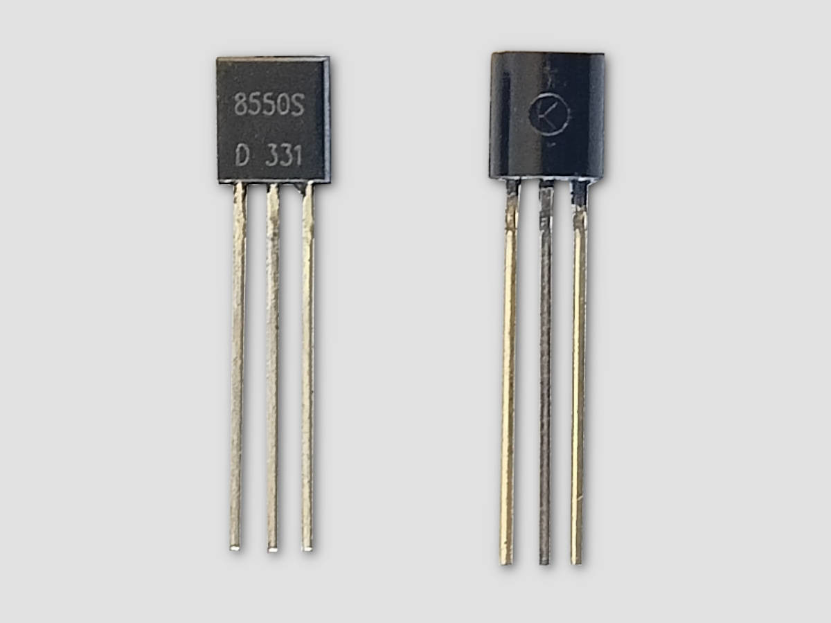
   TO-92 Package (Flat Side Facing You)

      _________
     |         |
     |         |
     |         |
     |         |
     |         |
     |_________|
      |   |   |
      |   |   |
     1   2   3
     |   |   |
     |   |   |
     E   B   C

   1 = Emitter
   2 = Base
   3 = Collector
-
E = Emitter
-
B = Base
-
C = Collector
You see the 8550 transistor pinout clearly in this diagram. The emitter sits on the left, the base in the middle, and the collector on the right. This layout matches the information in trusted datasheets and electronics guides. You can use this diagram as a quick reference when building or repairing circuits.
If you remember the correct 8550 transistor pinout, you protect your components and make your projects work better. Always check both the table and the diagram before connecting the transistor.
Pin Functions
Emitter
The emitter pin lets current flow out of the transistor. You connect this pin to the part of your circuit where you want the current to leave. In the 8550 transistor, the emitter usually connects to the negative side of your power supply. This pin releases charge carriers, which are tiny particles that carry electricity. If you connect the emitter incorrectly, your transistor will not work as expected.
Tip: Always check the emitter pin before powering your circuit. A wrong connection can stop the current flow and damage your components.
Base
The base pin acts like a gatekeeper. You use this pin to control when the transistor turns on or off. A small current into the base allows a much larger current to flow from the collector to the emitter. This process is called amplification. You can think of the base as a switch. When you apply a small voltage to the base, the transistor lets current flow through the other pins.
-
The base pin needs a resistor in most circuits.
-
This resistor limits the current and protects the transistor.
If you forget the resistor, you might send too much current into the base. That can damage the transistor quickly.
Collector
The collector pin collects the current that flows through the transistor. You connect this pin to the load in your circuit, such as a motor or an LED. The collector usually connects to the positive side of your power supply. When you send a signal to the base, the collector allows current to pass through to the emitter.
| Pin Name | Main Role in Circuit | Usual Connection Point |
|---|---|---|
| Emitter | Releases current | Negative (ground) |
| Base | Controls transistor action | Signal input (with resistor) |
| Collector | Collects current | Load or positive supply |
Remember: Correctly identifying and connecting each pin ensures your circuit works safely and efficiently.
Pin Identification
TO-92 Orientation
You need to hold the transistor the right way to identify its pins. The 8550 transistor comes in a TO-92 package, which has a flat side and three leads. Follow these steps to make sure you get the pin order correct:
-
Find the flat side of the transistor. This side usually has the part number printed on it.
-
Hold the transistor so the flat side faces you and the leads point downward.
-
Look at the three pins from left to right. The first pin is the Emitter, the middle pin is the Base, and the last pin is the Collector.
Tip: Always check the official datasheet for the 8550 transistor pinout. The datasheet gives you a clear diagram and confirms the pin order.
You can also use this table as a quick guide:
| Step | What to Do |
|---|---|
| 1 | Check the datasheet for the correct pinout and package type. |
| 2 | Identify the TO-92 package by its flat side and three leads. |
| 3 | Hold the transistor with the flat side facing you, pins down. |
| 4 | Read the pins from left to right: Emitter, Base, Collector. |
| 5 | Double-check with diagrams or 3D models in the datasheet if unsure. |
Common Mistakes
You might make some errors when identifying the pins. Here are the most common mistakes and how to avoid them:
-
Holding the transistor backward: If you face the curved side instead of the flat side, you will reverse the pin order.
-
Not checking the datasheet: Some transistors look similar but have different pinouts. Always confirm with the datasheet.
-
Assuming all TO-92 transistors have the same pinout: Different models can have different pin arrangements.
-
Skipping the resistor on the base: Forgetting this can damage the transistor.
Note: Double-check the orientation every time you use a new transistor. This habit helps you avoid wiring errors and protects your circuit.
When you follow these steps and avoid common mistakes, you can identify the 8550 transistor pinout quickly and safely.
You now know the correct 8550 transistor pinout: Emitter, Base, Collector from left to right with the flat side facing you. Always follow these steps:
-
Double-check the pin orientation before connecting.
-
Use diagrams and tables as quick references.
-
Confirm the pinout with the datasheet.
Careful pin identification keeps your circuits safe and prevents damage to your components.
FAQ
What happens if you connect the 8550 transistor pins incorrectly?
If you connect the pins wrong, the transistor will not work. You might damage the transistor or other parts in your circuit. Always check the pinout before connecting.
Can you use the 8550 transistor as a switch?
Yes, you can use the 8550 transistor as a switch. Apply a small current to the base. The transistor will let a larger current flow from collector to emitter.
How do you test the 8550 transistor with a multimeter?
Set your multimeter to diode mode. Touch the probes to the base and emitter, then base and collector. You should see a voltage drop in one direction. Reverse the probes. You should see no reading.
Do all TO-92 transistors have the same pinout as the 8550?
No, not all TO-92 transistors share the same pinout. Always check the datasheet for each transistor. This step helps you avoid wiring mistakes.
Why does the base need a resistor?
The base needs a resistor to limit current. Too much current can damage the transistor. The resistor keeps your transistor safe and working well.
Written by Jack from AIChipLink.
AIChipLink, one of the fastest-growing global independent electronic components distributors in the world, offers millions of products from thousands of manufacturers, and many of our in-stock parts is available to ship same day.
We mainly source and distribute integrated circuit (IC) products of brands such as Broadcom, Microchip, Texas Instruments, Infineon, NXP, Analog Devices, Qualcomm, Intel, etc., which are widely used in communication & network, telecom, industrial control, new energy and automotive electronics.
Empowered by AI, Linked to the Future. Get started on AIChipLink.com and submit your RFQ online today!