What Are Carbon Film Resistors

A carbon film resistor is a fixed resistor using a thin carbon layer on a ceramic rod to limit current. You will find this passive component in many basic circuits, from power supplies to LED lighting. Knowing how carbon film resistors work helps you pick the right part for your projects.
For beginners, these resistors are a cheap way to start in electronics. They are used in consumer devices, industrial controls, and school breadboard experiments. Carbon Film Resistors appear often in repair work and prototyping.
This article explains how they are built, their main specs, and how they compare to metal film resistors. You will learn useful skills for reading color codes and picking parts for your circuits.
Key Takeaways
-
Carbon film resistors are a cheap option for regular circuits, but they make more noise and are less stable than metal film resistors.
-
The color bands on a carbon film resistor tell you its resistance value and tolerance, making it easy to identify.
-
Use carbon film resistors for low-cost projects where exact resistance is not important, like LED circuits and power supplies.
-
For audio or precise jobs, choose metal film resistors to get lower noise and steadier temperature performance.
How Carbon Film Resistors Are Made
Understanding the manufacturing process helps you appreciate what makes carbon film resistors reliable and affordable. The production involves two main stages: depositing the carbon layer and trimming it to the exact resistance value.
Substrate and Carbon Film Deposition
The journey begins with a ceramic rod that forms the core of every carbon film resistor. Manufacturers choose ceramic materials for specific reasons. Alumina stands out as a state-of-the-art option because it offers extreme hardness and high thermal conductivity. This hardness means the material resists wear during processing, while the thermal conductivity helps diffuse heat effectively during operation. Steatite serves as a cost-effective alternative with good electrical properties, including low dielectric loss for radio-frequency applications. Steatite also forms and fires at lower temperatures, which simplifies production.
The deposition process follows a precise sequence:
-
Place the ceramic rod in an environment with high temperature and pressure.
-
Pass hydrocarbon gas, such as methane or benzene, over the rods at a temperature around 1000°C.
-
At this temperature, the hydrocarbon gas thermally decomposes, depositing a thin film of pure carbon onto the rods.
-
Attach end caps to the rods to connect to the carbon film.
-
Trim the resistance value by making a helical cut in the carbon film.
-
Coat the resistors in a resin for protection against handling, moisture, and contaminants.
This thermal decomposition method creates a uniform carbon layer that adheres firmly to the ceramic surface. The thickness of this film directly influences the base resistance level before trimming begins.
Helical Cutting and Tolerance
The helical cutting process transforms a simple coated rod into a precise resistor. A spiral groove is cut into the carbon layer to increase the current path length. This longer path forces electrons to travel farther, which raises the resistance value. The manufacturer controls the final resistance by adjusting the groove density:
-
Lower groove density with wider spacing results in lower resistance.
-
Denser grooves increase the effective conductive path length.
-
The precision of this mechanical grooving depends on film uniformity.
However, this mechanical approach has limitations. Fluctuations in film thickness and density during deposition create slight variations across each batch. Irregular burrs at the edges of the grooves add further inconsistency. These factors restrict the achievable tolerance to a typical range of ±5% to ±10%, with some lower-end products reaching ±20%.
According to industry selection guidelines, carbon film resistors are typically specified with tolerances of ±2% to ±5%. This confirms that the ±2% value represents the tighter end of the standard commercial range, achievable when the helical cutting process runs with higher precision on more uniform film deposits.
The tolerance rating tells you how much the actual resistance can vary from the labeled value. A resistor marked 100Ω with a ±5% tolerance might measure anywhere between 95Ω and 105Ω. This variation matters when you design circuits that require precise voltage division or current limiting.
The resin coating applied at the end serves multiple purposes. It protects the delicate carbon film from physical damage during handling. It also shields the resistor from moisture and environmental contaminants that could alter the resistance over time. This protective layer extends the operational life of carbon film resistors in real-world applications.
The entire manufacturing process balances cost against precision. Carbon film resistors achieve acceptable accuracy for general-purpose use while keeping production expenses low. This efficiency explains why you find these components in consumer electronics, educational kits, and prototyping projects where extreme precision is unnecessary.
Key Specifications of Carbon Film Resistors
Carbon film resistors are fixed-value parts. You cannot change their resistance after they are made. The helical cutting process sets the final value for good. This fixed nature makes them predictable and simple to use in circuit design.
Resistance Value and Tolerance
The resistance value tells you how much the part resists current flow. Makers mark this value with color bands on the body. You can find carbon film resistors in standard values that follow the E-series system.
Tolerance tells you how much the real resistance can differ from the marked value. Carbon film resistors usually have ±5% tolerance, which puts them in the E24 series. This series gives 24 standard values per decade. Some cheaper carbon film resistors have ±10% tolerance, matching the E12 series with 12 values per decade. The table below shows how tolerance classes relate to available values:
| Tolerance Class | Corresponding E-Series | Values per Decade |
|---|---|---|
| ±20% | E6 | 6 |
| ±10% | E12 | 12 |
| ±5% | E24 | 24 |
| ±2% | E48 | 48 |
| ±1% | E96 | 96 |
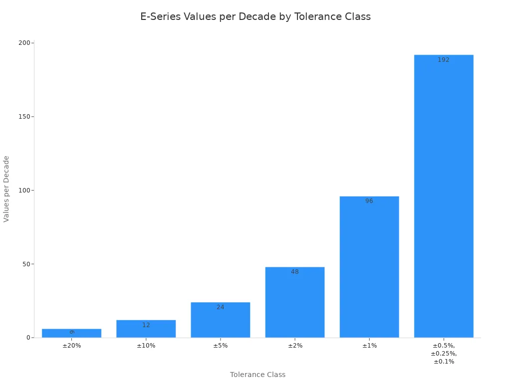
A ±5% resistor marked 100Ω may measure between 95Ω and 105Ω. This variation matters when you design circuits that need exact voltage division.
Power Rating and Temperature Coefficient
Power rating shows how much heat a resistor can give off without damage. Carbon film resistors usually handle 1/8 W to 1/2 W. Makers rate these values at an ambient temperature of 70°C. If the air around it gets hotter, the resistor's ability to shed heat goes down. A 1/4 W resistor working at 100°C may only safely give off 0.1 W. You must lower the rating for hot places.
The temperature coefficient of resistance (TCR) measures how much the resistance changes with temperature. Carbon film resistors have TCR values of 200 to 500 ppm/°C. This means the resistance changes by 200–500 parts per million for every 1°C change. In a voltage divider for a temperature sensor, this drift causes wrong readings. The table below shows key operating limits:
| Parameter | Value |
|---|---|
| Maximum working voltage range | 200 – 600 V |
| Operating temperature range | −55 °C to 155 °C |
These specs show where you can safely use carbon film resistors. Their high TCR makes them less stable in places where temperature changes. For general circuits with medium temperature swings, they work fine. For precision uses, you should think about metal film resistors with lower TCR values.
How to Read Carbon Film Resistor Markings
You can find a carbon film resistor's value by reading the color code printed on its body. Colored bands wrap around the cylindrical part. Each color stands for a number, multiplier, or tolerance. This system lets you identify the resistance without any special tools. Learning to read these bands helps beginners and experts alike work with carbon film resistors quickly.
4-Band and 5-Band Color Codes
The 4-band system uses four colored bands. The first two bands give the significant digits. The third band is the multiplier. The fourth band shows the tolerance. For example, a carbon film resistor with bands of red (2), violet (7), green (5 zeros), and gold (±5%) gives a resistance of 2,700,000 ohms, or 2.7 MΩ. This pattern works the same way for all 4-band carbon film resistors.
The 5-band system adds a third significant digit for higher precision. The first three bands give the digits. The fourth band is the multiplier. The fifth band shows the tolerance. You find 5-band codes on carbon film resistors with tighter tolerance values like ±2%. The additional digit gives you more precise resistance values. Many beginners struggle with 5-band codes at first.
Multiplier and Tolerance Bands
The multiplier band tells you how many zeros to add after the digits. In the 4-band system, the third band holds this role. A green multiplier means you add five zeros. A red multiplier means you add two zeros. The multiplier band determines the final resistance value for the carbon film resistor you are reading.
The tolerance band tells you how much the actual resistance can vary from the marked value. Carbon film resistors use standard tolerance colors:
| Color | Tolerance |
|---|---|
| Gold | ±5% |
| Silver | ±10% |
| Red | ±2% |
Gold is the most common tolerance band for carbon film resistors. You see it on parts that meet the standard ±5% tolerance. Silver indicates a ±10% tolerance, which appears on cheaper carbon film resistors. Red indicates a ±2% tolerance, which marks the tighter end of the range for carbon film resistors. When you read a carbon film resistor, always check the tolerance band last. It tells you the expected accuracy of the part for your circuit. These color codes make carbon film resistors easy to identify without special tools. Using color codes saves time when you work with carbon film resistors.
Carbon Film Resistors vs. Metal Film Resistors
Performance and Noise
When you pick a resistor for a circuit, you need to compare carbon film and metal film types. The two parts look alike, but they work very differently. Carbon film resistors have lower accuracy and more noise. Metal film resistors give better precision and cleaner signals. For your DIY projects, this difference matters a lot. A carbon film resistor is a good choice for simple circuits.
The table below shows the key performance differences between carbon film and metal film resistors:
| Performance Parameter | Carbon Film Resistor | Metal Film Resistor |
|---|---|---|
| Resistance Tolerance (Accuracy) | ±5% to ±10% | ±0.1% to ±1% |
| Long-Term Stability (Drift) | >5% after five years | <1% |
| Temperature Coefficient (TCR) | ±100 to ±300 ppm/°C | ±10 to ±50 ppm/°C |
Metal film resistors are clearly better in every accuracy measure. A metal film resistor keeps its value within tighter limits. It also drifts less over time. Its temperature coefficient is much lower. This means resistance changes less when temperature shifts. For your DIY projects that need stable performance, metal film is the better choice. A thin-film resistor offers even better precision than standard metal film.
Noise is another major difference. Carbon film resistors have medium-high excess noise. The noise level ranges from -18 dB to -10 dB. This equals about 0.126 µV/V to 0.316 µV/V per decade. This noise comes from the current path through oxide particles. Electrons bunch up and release suddenly. This causes hiss and distortion in audio signals. For your DIY circuits, this noise matters most in audio circuits. Metal film resistors offer much lower noise levels. They work well for precision audio and instrumentation circuits. Each resistor you choose affects the final sound quality.
However, carbon film resistors have a place in some audio projects. You can use them in budget-friendly audio builds. Cost is the priority in these projects. Basic portable speakers and low-end radios work fine with carbon film resistors. The noise is not a big concern in these projects. Carbon film resistors also work in power amplifier output stages. They handle surge current well despite their higher noise. This gives them a specific role in certain DIY projects. Many DIY projects use them for this reason.
Cost and Applications
Cost is the main advantage of carbon film resistors. When you buy them in bulk, the price difference is large. Carbon film resistors cost about 1/3 to 1/5 of the price of metal film resistors. For large-quantity orders, this saving adds up fast. For your DIY projects, this cost difference matters when you need many resistors. The right resistor can save you a lot of money.
The common uses in DIY are many. You find carbon film resistors in home appliance control boards. Washing machines and refrigerators use them. These circuits need only basic current limiting and voltage division. They do not need high precision. Standard power supply circuits also use carbon film resistors. These circuits handle voltage division and current limiting. The low precision requirements make carbon film a good fit. LED drivers for indicator lights and general lighting use carbon film resistors. These circuits need basic current limiting. Cost is the priority in these volume applications. General electronics and auxiliary circuits also use them. Simple switches and indicator light drivers work well with them. Cost control is very important in these designs. All these circuits benefit from the low cost.
For your DIY projects, the choice depends on your needs. If you build a precision audio amplifier, choose metal film. If you build a simple LED circuit, carbon film works fine. The performance in DIY circuits depends on matching the resistor type to the application. Use carbon film resistors where cost matters and precision does not. Use metal film where accuracy and low noise are critical. All projects benefit from careful part selection.
You now understand how a carbon film resistor works. A ceramic core, carbon layer, and helical cut create a fixed resistance value. These parts offer simple construction, low cost, and wide availability. They suit many general-purpose applications.
Carbon film resistors remain relevant despite their limitations. Their inexpensive manufacturing keeps them accessible for hobbyist projects and industrial electronics. You can find them easily in various values and power ratings. Their robust design handles essential functions like voltage division and current limiting.
The trade-offs matter. You accept higher noise and temperature sensitivity for lower cost. In audio projects, some builders prefer their warm tonal character. For budget-conscious projects, educational kits, and prototypes, they remain a practical choice. Your projects benefit from knowing when to choose them.

Written by Jack Elliott from AIChipLink.
AIChipLink, one of the fastest-growing global independent electronic components distributors in the world, offers millions of products from thousands of manufacturers, and many of our in-stock parts is available to ship same day.
We mainly source and distribute integrated circuit (IC) products of brands such as Broadcom, Microchip, Texas Instruments, Infineon, NXP, Analog Devices, Qualcomm, Intel, etc., which are widely used in communication & network, telecom, industrial control, new energy and automotive electronics.
Empowered by AI, Linked to the Future. Get started on AIChipLink and submit your RFQ online today!
Frequently Asked Questions
Can I use carbon film resistors in audio circuits?
Yes, you can use them in audio circuits. They create more noise than metal film types, which causes hiss in sensitive signal paths. However, many builders like their warm sound in guitar pedals and vintage-style amplifiers. For budget audio builds, they work well enough.
How do I choose between carbon film and metal film resistors?
Match the resistor type to what your circuit needs. Pick carbon film for simple circuits where cost is most important. Pick metal film when you need accuracy and low noise. For most hobby electronics, carbon film works fine. For sensitive measurements, metal film works better.
What does the tolerance band on a carbon film resistor mean?
The tolerance band shows how much the actual value can differ from the marked value. A gold band means ±5% difference. A silver band means ±10%. A 100Ω resistor with gold tolerance measures between 95Ω and 105Ω. This matters for circuits that need exact voltage division.
Are carbon film resistors good for beginners?
Yes, they are great for beginners. Their low cost lets you try things freely without worrying about money. You can buy large sets cheaply for breadboard work. Their color codes teach you useful identification skills. Many starter kits include them for this reason.