Building a Toy Organ Circuit using 555 Timer IC
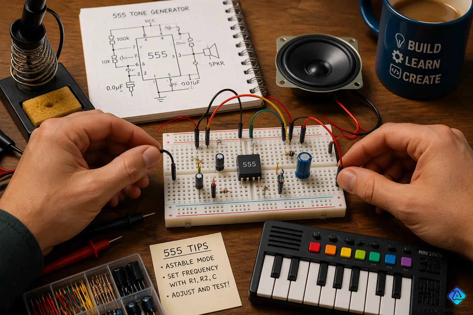
A toy organ circuit turns a few cheap parts into a playable musical toy. You can build the whole thing around one 555 timer ic, and that is the real charm here. This simple toy organ needs no programming and no fancy tools. It just shows you how an oscillator makes sound.
Think of it as a simple monophonic musical instrument. You press a key, and the circuit plays one note at a time. That monophonic setup keeps the wiring easy to follow. The timer ic handles the tone generation, so you focus on learning.
A mini electronic organ like this costs very little. The organ fits on a breadboard in an afternoon. You get a clear, hands-on lesson in oscillator basics.
Key Takeaways
-
Build a toy organ with a 555 timer IC and a few cheap parts.
-
The 555 timer works in astable mode to create sound tones.
-
Change resistor and capacitor values to play different notes.
-
Use the circuit as a fun way to learn electronics and STEM.
-
Add more keys or swap the speaker to expand your toy organ.
Toy Organ Circuit Diagram and Parts
Circuit Diagram Overview
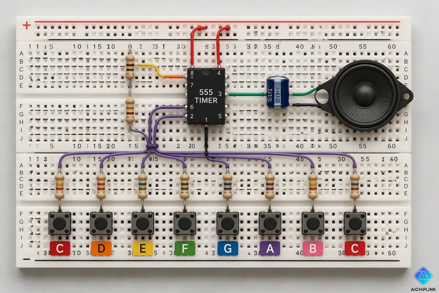
The full circuit diagram for this toy organ circuit is simple enough to hold in your head after one look. Picture the 555 timer ic sitting in the center. Eight pins fan out from the body, and each one has a clear job. Pin 8 and pin 4 tie to the positive supply rail. Pin 1 goes to the negative rail, which is ground. Pin 3 is the output, and it drives the speaker through a coupling capacitor. Pins 2 and 6 connect together across the timing capacitor, and that junction also links to the resistor network your keys switch in. Pin 7 sits between the two timing resistors and handles the discharge path. Pin 5 is left open or tied to ground through a small capacitor for stability. The speaker sits between pin 3 and ground, with the coupling capacitor in line to block DC.
Now set the chip on your breadboard. Place the chip so the notch or dot faces up. That orientation puts pin 1 at the top left and pin 8 at the top right. Run a jumper from pin 8 to the positive rail. Run another jumper from pin 1 to the negative rail. Double-check those two before you power anything. A reversed supply is the fastest way to kill the chip. Keep the chip's legs straight and seated fully in the breadboard holes.
The keys are simple push buttons. Each button connects a different resistor into the timing path. Press one, and the circuit plays its note. Release it, and the sound stops. That is the whole trick behind the toy. Wire the buttons in parallel, with each one in series with its own resistor. The common ends meet at pins 2 and 6. Keep those button leads short on the breadboard. Long leads pick up noise and make the pitch wobble. Label each button with its note before you wire it. That small step saves confusion later. A tidy layout makes troubleshooting easy.
Component List
Here is what you need to gather before you start breadboarding.
| Part | Value / Type | Qty | Purpose |
|---|---|---|---|
| 555 timer IC | Bipolar or CMOS | 1 | Generates the tone |
| Timing resistor (R1) | 1 kΩ or higher | 1 | Limits discharge current |
| Timing resistors (R2) | 1 kΩ to 1 MΩ | 5 | Sets each note's pitch |
| Timing capacitor (C) | 1 µF to 1000 µF electrolytic | 1 | Sets the timing window |
| Coupling capacitor | Small film or ceramic | 1 | Blocks DC from the speaker |
| Push buttons | Momentary, normally open | 5 | Select notes |
| Speaker | Small 8 Ω | 1 | Makes sound audible |
| Battery | 4.5V to 15V | 1 | Supplies power |
Pick resistor values that land your tones between 200 Hz and 4 kHz, the range where the 555 astable circuit works well for audio. A CMOS 555 draws less power and reaches higher frequencies. A bipolar 555 gives you stronger output drive. Either one works fine here. For accurate notes, use precision resistors and a low-tolerance capacitor. Cheap parts drift, and drift means sour notes. Always check the supply voltage against your chip's rating before you connect the battery. The table gives you a starting point, not a fixed recipe.
How the 555 Timer IC Works
Astable Multivibrator Mode
In astable multivibrator mode, the 555 timer ic never settles into one state. It flips between high and low on its own, over and over, with no help from you. That constant flipping is what makes sound possible. Each flip charges and discharges the timing capacitor, and the output at pin 3 swings with it. Feed that swinging signal to a speaker, and you hear a continuous tone.
The astable multivibrator works like a self-resetting switch. The capacitor charges through the resistors until it hits a threshold, then dumps its charge and starts again. This cycle repeats thousands of times per second. Your ear hears those repeats as a single pitch. Change how fast the cycle runs, and the pitch changes with it. That is the whole secret behind the tones produced by this little circuit.
Frequency Formula and Note Selection
The frequency of oscillation depends on three parts: R1, R2, and the timing capacitor. The standard astable frequency formula ties them together:
Frequency, f = 1.44 / ((R1 + 2R2) C)
Here R1 and R2 are the timing resistors in ohms, and C is the timing capacitor in farads. The result comes out in hertz. Notice that R2 counts twice. That happens because the capacitor charges through both resistors but discharges through R2 alone. The timing breaks down like this:
-
Time High (T1) = 0.693 × (R1 + R2) × C1
-
Time Low (T2) = 0.693 × R2 × C1
-
Time Period (T) = T1 + T2 = 0.693 × (R1 + 2R2) × C1
-
Frequency (f) = 1 / T = 1.44 / ((R1 + 2R2) × C1)
-
Duty Cycle (%) = (R1 + R2) / (R1 + 2R2) × 100
No single resistor and capacitor pair owns a given frequency. You can trade one against the other. Pick a capacitor you have on hand, then solve for the resistors. Keep an eye on duty cycle too. A combination closer to 50% gives you a squarer wave. Ordinary resistors drift with temperature, so the actual frequency can shift. Use temperature-stable resistors when pitch accuracy matters.
Now for the keys. Each push button taps a different point along the resistor chain. Press a button, and you connect a specific resistance between pin 7 and the timing network. That changes the effective resistance in the astable frequency formula. A different resistance means a different output frequency, and a different pitch reaches your ear. The square wave leaves pin 3, passes through the coupling capacitor, and drives the speaker. Press one key at a time, because this design is monophonic. Each button gives you a distinct note, and a handful of buttons gives you a playable scale of musical notes.
Toy Organ Applications and Modifications
Practical Uses
This toy organ circuit is a great teaching tool. It shows how an astable multivibrator works, and you can see that change as you press each key. Learners also pick up how RC timing circuits behave in a real setup. The parts are easy to see, the sound comes right away, and the lesson stays with you.
It also works well as a hands-on STEM activity. Kids learn basic electronics ideas through play instead of a textbook. Beginners, students, and hobbyists all fit the same group here. Each one wants to see the 555 timer's job in astable mode while building something they can interact with. A simple toy organ gives them that without a steep learning curve.
Expanding the Circuit
You can change the pitch by swapping resistor and capacitor values. The link between them is inverse: more resistance means lower frequency. Raising the resistance in series with the capacitor lowers the frequency, and lowering it raises the frequency. The formula f = 1.44 / ((R1 + 2 × R2) × C1) controls the result. You can rearrange it to solve for a target tone: R2 = ((1.44 × 10^7) / f) − 500. That gives you a range of frequencies to try.
Adding more keys is the next step. Each extra button and resistor pair gives you another note, so a five-key toy organ grows into a fuller scale of musical notes. Keep the monophonic design in mind as you expand. One key plays at a time, and that keeps the wiring simple. Swapping a buzzer for a speaker is another easy upgrade. A speaker plays the tone with more body, and the circuit stays the same.
You now have a project that proves how much a single chip can do. The 555 timer ic keeps the build simple, and the low cost makes it easy to start today. You also get real practice with the timer in astable mode, where it oscillates on its own and sets pitch through resistor and capacitor values.
A handful of parts becomes a working musical toy. Your toy organ circuit turns button presses into clear notes, and the whole toy organ fits on one breadboard. That is the fun of this circuit.
Try new resistor and capacitor values. Add keys, or swap in a speaker. Keep exploring, and your next build will teach you even more.

Written by Jack Elliott from AIChipLink.
AIChipLink, one of the fastest-growing global independent electronic components distributors in the world, offers millions of products from thousands of manufacturers, and many of our in-stock parts is available to ship same day.
We mainly source and distribute integrated circuit (IC) products of brands such as Broadcom, Microchip, Texas Instruments, Infineon, NXP, Analog Devices, Qualcomm, Intel, etc., which are widely used in communication & network, telecom, industrial control, new energy and automotive electronics.
Empowered by AI, Linked to the Future. Get started on AIChipLink and submit your RFQ online today!
Frequently Asked Questions
What supply voltage does the toy organ need?
The circuit runs on anything from 4.5V to 15V, so a small battery pack works fine. Check your chip's rating before you connect power. A CMOS 555 draws less current, which stretches battery life. Keep the supply steady, because a sagging battery pulls the pitch down.
Why does my organ play only one note at a time?
That is by design. The circuit is monophonic, so each button connects one resistor path to the timing network. Press two keys together and the resistances combine, which gives you a muddled pitch. Play one key at a time and every note stays clean.
I pressed a key and heard nothing. What should I check?
Start with the chip orientation. The notch must face up, with pin 8 on the positive rail and pin 1 on ground. Then check the coupling capacitor and the speaker leads. A reversed supply kills the chip, so verify polarity before you swap parts.
Can I use a CMOS 555 instead of a bipolar one?
Yes, either type works in this build. The CMOS version draws less power and reaches higher frequencies. The bipolar version gives you stronger output drive for the speaker. Match your choice to what you need, then keep the pinout the same.
How do I tune a key to a specific note?
Pick your timing capacitor first, then solve the frequency formula for R2. The article gives you a rearranged version for that. Use precision resistors and a low-tolerance capacitor, since cheap parts drift and drift means sour notes.