Joule Thief Circuit: A Low-Power Voltage Booster
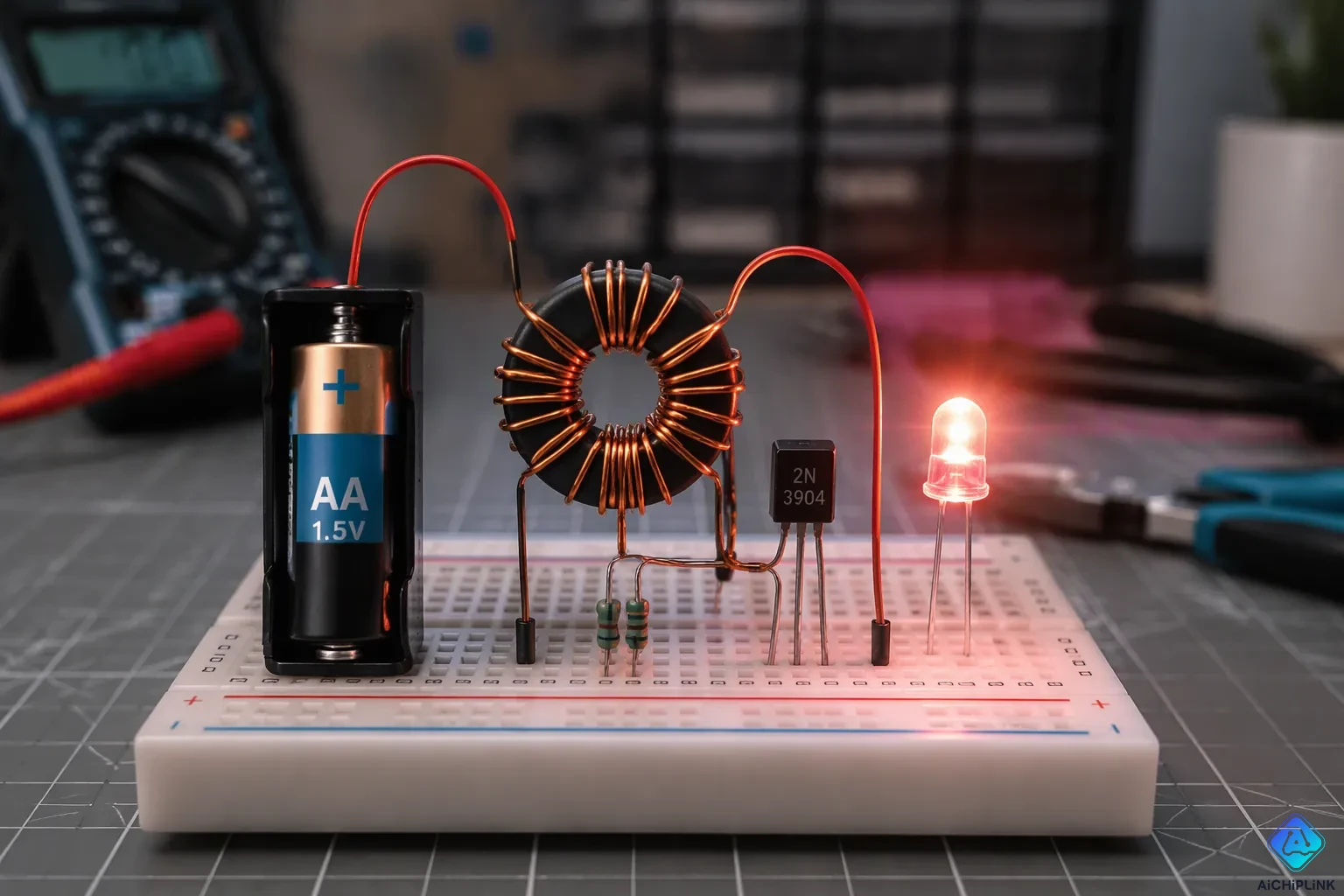
A joule thief circuit is a boost converter that switches itself on and off. It takes usable energy from low-voltage sources, like a nearly dead battery. It does this by quickly switching a transistor and an inductor to make high-voltage pulses that light an led.
This joule thief circuit is related to the blocking oscillator. It also belongs to the unregulated boost converter family, so you get a simple voltage booster with no control loop.
Here a joule thief circuit works as a low-power voltage booster. You will see how its switching phases raise the voltage, and where it fits. A few cheap parts, about $2–5, no microcontroller, and a weak battery still keep an led glowing.
Key Takeaways
-
A joule thief circuit boosts low voltage from weak batteries to light an LED.
-
The circuit switches itself on and off without a clock chip or microcontroller.
-
You can build it with cheap parts like a transistor, inductor, and resistor.
-
It works with batteries that other devices reject, but output power is low.
-
Check the winding polarity first if your circuit stays dark.
How a Joule Thief Circuit Works
The Self-Oscillating Boost Principle
A joule thief circuit is a boost converter that switches itself on and off. It changes a low DC voltage into pulses of higher voltage. You do not need a clock chip or a microcontroller to make this happen. The circuit makes its own timing.
The joule thief circuit is a type of blocking oscillator. It also counts as an unregulated boost converter. The battery sends a steady current. The transistor chops that current in a PWM-like pattern. Each switching cycle stores energy and then releases it at a higher voltage. This is the heart of how it works.
The feedback winding drives the switching action. A small base current turns the transistor on. Current ramps up through the primary winding. The feedback winding then pushes the base harder. This positive feedback keeps the switching going until the core nears saturation. At that point the feedback drops and the transistor switches off. The stored energy then leaves the coil as a voltage spike.
The lowest voltage limit comes from the transistor's base-emitter voltage. A source as low as about 0.6V can still start conduction. That is why this way of working suits low input voltage sources so well. The boost converter needs only a tiny push to begin switching.
Why Weak Batteries Still Hold Energy
A battery that looks dead to most devices still holds charge. The joule thief circuit drains that last bit of power. One build drove a 3V LED using a battery that measured only about 0.91V. The same cell ran fairly bright across a range of 0.4V to 1.0V. This shows that a dead battery keeps usable energy at low voltages.
The problem is internal resistance. A weak battery can read close to its normal voltage at rest. Under load, the terminal voltage drops. A depleted cell may hold normal voltage while its usable capacity has shrunk a lot. A device powers on and then shuts down within minutes.
The joule thief circuit gets around this limit. It draws current in short switching bursts instead of a steady heavy load. The low input voltage still feeds the coil. The voltage boosting happens in the coil, not in the battery. That is why this booster recovers energy other circuits reject.
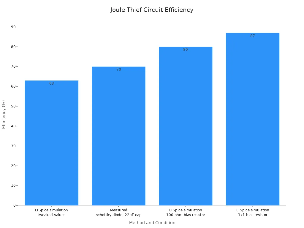
Efficiency varies by design. Reported results range from about 63% in simulation to about 87% with a 1k1 bias resistor in simulation. A measured build with a schottky diode and filter cap reached about 70%. Real LED efficiency is likely a little higher.
Key Components and Roles
Transistor, Inductor, and Feedback Winding
A common build uses a BC337 transistor with two windings on a toroid core. You wind the primary and the feedback coil on the same core. The feedback coil connects in opposing polarity to the primary. This feedback polarity matters for the joule thief circuit.
When collector current starts to flow, the feedback coil induces a voltage that raises the base bias. This positive feedback drives the transistor into saturation. The collector-emitter path acts like a closed switch. Primary current then ramps up through the inductor. When the coil current stops rising, the same feedback action reverses. The transistor switches hard off. The collapsing field keeps the load conducting, and the cycle repeats. The feedback coil thus drives transistor switching fully on and fully off, and that sustains the oscillation.
A two-transistor configuration can drive multiple LEDs. Use the single-transistor build for one LED and a weak battery. Choose the two-transistor version when you need more current or several emitters at once. The single-transistor joule thief circuit suits one indicator lamp. The two-transistor version fits small multi-lamp projects.
Resistor, LED, and Power Source
The resistor sets the base current. A larger value limits the drive and saves power. The LED sets the output voltage ceiling, because it clamps the spike. Pick the resistor value to match your supply voltage and your target brightness.
-
LEDs need 2V or more to light (forward voltage).
-
A joule thief circuit can drive 3V blue or white LEDs from a nearly dead cell at about 0.8V under load.
-
Example superbright red LEDs are rated at 70mA each; ten of them need 700mA total.
-
Their forward voltage is about 2V.
The battery supplies the low input voltage. Short switching bursts pull current, so a weak cell still works. Match the emitter count to the transistor's current rating. A fresh battery is not required for this joule thief circuit.
Watch the transistor switching as you test. The feedback winding keeps the switching steady across a range of input voltage. Each transistor switching cycle repeats, and a weak battery can supply it for a long time.
Joule Thief Circuit Diagram and Wiring
Reading the Schematic
A joule thief circuit diagram looks simple at first glance. You see a transistor, a resistor, an inductor with two windings, and an led. The tricky part is the winding polarity. The primary and feedback coils share one core, and their phasing decides whether the circuit oscillates.
It does matter which two wires you connect together which end up going to the positive battery terminal. If your core doesn't work select the other pair of wires. Or wind your wires as can be seen in the Wikipedia photo at the top of this page.
Treat the joule thief schematic as a loop. The battery feeds the primary winding through the transistor. The feedback winding sits between base and emitter. Get the phasing wrong and the transistor never turns on. Swap the two leads and the switching starts.
Two references help you check your work. Big Clive's "MAKE A JOULE THIEF" page shows how to connect the windings of ferrite core inductors. The Wikipedia "Bifilar coil" article explains how to wind the coil and the different connections.
Building It Step by Step
Gather your tools and parts before you start. This table lists what a typical build needs.
| Category | Items Required |
|---|---|
| Tools | Soldering iron; wire strippers; scissors; double-stick foam tape |
| Materials | D-size battery box with leads; battery-shell adapter set; 10 mm superbright white LED; 24-gauge wire from old network cable; toroid transformer core (at least ¾-inch ID); flashlight push-button switch; 1-kilohm resistor; 1-inch round protoboard; 2N2222 NPN transistor; dead AAA/AA/C/D alkaline battery |
Follow these steps to assemble the joule thief circuit diagram on the protoboard:
-
Wind the primary and feedback coils on the toroid with the 24-gauge wire.
-
Solder the 2N2222 transistor and the 1-kilohm resistor to the protoboard.
-
Connect the windings to the transistor, then check the polarity against the schematic.
-
Wire the led and the push-button switch.
-
Attach the battery box leads and insert the dead cell.
Test the circuit. If the led stays dark, reverse the winding pair that feeds the positive terminal. A working joule thief circuit lights the led from a cell other devices reject.
Oscillation Phases and Voltage Boost
The oscillation in a joule thief circuit runs as a repeating two-part cycle. Coiled copper wires create a feedback loop. That loop keeps the oscillation going without any timer chip. You can follow the action in two phases.
Phase 1 — Turn-On and Energy Storage
A tiny current enters the transistor base through a resistor and one inductor winding. This small push partly turns the transistor on. The sequence then happens fast:
-
The transistor conducts and drives a larger current through the second winding. The ferrite core concentrates the growing magnetic field, so the coil can store energy in a magnetic field.
-
The changing magnetic field causes a voltage in the second winding through mutual inductance. This induced voltage adds to the base current and strengthens transistor conduction. You now have a positive feedback loop, and it acts very quickly.
-
The ferrite core saturates. The induced voltage disappears, base drive is lost, and the transistor switches off almost instantly.
No specific time value applies to this phase. The evidence describes it as happening very quickly. The whole cycle repeats hundreds of thousands of times per second. That fast switching is the engine behind voltage boosting in this boost converter.
Phase 2 — Switch-Off and the Voltage Spike
The sudden switch-off produces the voltage spike. Inductive switching works like this: current through the coil cannot stop instantly. The magnetic field collapse forces the current onward, and the voltage rises sharply. This is where the real voltage boosting happens.
The spike size depends on the setup. The table below shows reported values.
| Condition / Setup | Reported Voltage Spike Magnitude |
|---|---|
| General switching-off spike (relative to original voltage) | 10× to 100× the original voltage (the circuit's "Q") |
| Spike delivered to LED load | Over 10 V (clamped to ~3.2–3.6 V by the LED) |
| With LED load, typical multimeter reading | 2.7–3.9 V depending on LED color |
| No load (especially with capacitor(s) in circuit) | 45–60 V |
| Large-coil setup (Slayer007) from a 12 V battery | 1000 V output |
The led clamps the spike. A spike over 10 V is enough to forward-bias the led, and the led holds the voltage near its own forward drop. You must forward bias the led for light to appear. The stored magnetic energy leaves the coil and passes through the emitter. Each switching cycle repeats this pattern, and the oscillation continues as long as the battery supplies current.
Watch the feedback loop as you test. The coiled wires keep the oscillation alive, and the switching stays steady. This is how a simple joule thief circuit turns a weak cell into a working light.
Demonstration, Applications, and Limits
Measuring the Boost
You can check the boost with a multimeter, but treat the readings with care. Measure input current in series with the battery and output current in series with the led. The table below shows what one test build produced.
| LEDs | Cells | Input current (mA) | Output current (mA) |
|---|---|---|---|
| 1 | 1 | 44.0 | 8.7 |
| 2 | 1 | 47.0 | 3.5 |
| 3 | 1 | 48.0 | 1.9 |
| 1 | 2 | 113.0 | 1.2 |
| 2 | 2 | 83.6 | 13.6 |
| 3 | 2 | 87.5 | 7.5 |

Output voltage is harder to trust. One author tried to read the voltage across the led, and the meter only returned the input voltage. A standard DMM cannot follow the fast pulses.
Voltage measurements at different circuit points are unreliable with a standard DMM.
A scope gives a truer picture. With the battery at about 0.55 V, the stock joule thief circuit drew 3–4 mA. Adding a 10 nF capacitor cut the draw to about 1.5 mA and dimmed the led.
Where It Shines and Where It Falls Short
This boost converter excels at powering leds from weak batteries. It also suits energy harvesting. A Peltier tile driven by body heat can power an led from as little as about 30 mV. Piezoelectric discs, small solar cells, and wind-driven fans all feed it well. Bicycle lights and portable reading lamps are natural fits.
The limits matter too. Output power stays low, so the circuit cannot drive heavy loads. Output voltage is unregulated and arrives as pulses, which rules out sensitive electronics. Efficiency typically lands at 40–60%, and a supercharged variant passes 80%. Rapid switching also creates electrical noise. Performance depends on the transistor, the coil winding, and the core material. The circuit cannot charge a battery.
A low base-emitter voltage starts the joule thief circuit working. The feedback winding then pushes the transistor fully on, and the inductor stores energy. The sudden switch-off makes a voltage spike, and the led holds that spike and uses it.
This booster matters for three reasons. It needs very few parts, it switches on and off without a clock, and it pulls energy from sources other circuits throw away. A weak battery still runs it.
Build one on a breadboard next. Measure the output voltage with a meter or scope, then change the turns ratio and resistor values. If the switching stops, check the dot convention and reverse one coil's connections. That one fix brings back oscillation in most joule thief circuit builds.

Written by Jack Elliott from AIChipLink.
AIChipLink, one of the fastest-growing global independent electronic components distributors in the world, offers millions of products from thousands of manufacturers, and many of our in-stock parts is available to ship same day.
We mainly source and distribute integrated circuit (IC) products of brands such as Broadcom, Microchip, Texas Instruments, Infineon, NXP, Analog Devices, Qualcomm, Intel, etc., which are widely used in communication & network, telecom, industrial control, new energy and automotive electronics.
Empowered by AI, Linked to the Future. Get started on AIChipLink and submit your RFQ online today!
Frequently Asked Questions
What input voltage does a joule thief circuit need to start?
The transistor's base-emitter junction sets the floor. Conduction begins near 0.6V, so a source at that level can start the switching. Builds have lit a 3V LED from a cell reading about 0.91V, and the same cell worked across 0.4V to 1.0V.
Why does my joule thief circuit stay dark?
Check the winding phasing first. The primary and feedback coils share one core, and the wrong pair of leads stops oscillation. Reverse the two wires that feed the positive terminal. That single swap restores switching in most builds.
Can I drive more than one LED from a single transistor?
Yes, within the transistor's current rating. A two-transistor configuration handles several emitters at once. Choose the single-transistor build for one lamp and a weak battery. Pick the two-transistor version when you need more current or multiple emitters.
How efficient is this voltage booster?
Expect roughly 40–60% in a typical build. A supercharged variant passes 80%, and a measured build with a schottky diode and filter cap reached about 70%. Output power stays low, so heavy loads are out of reach.
Can I measure the output with a standard multimeter?
Not reliably. The output arrives as fast pulses, and a standard DMM cannot follow them. One author read only the input voltage across the LED. Use a scope for a truer picture of the spike.