10 Common Mode Chokes for EMI Filtering
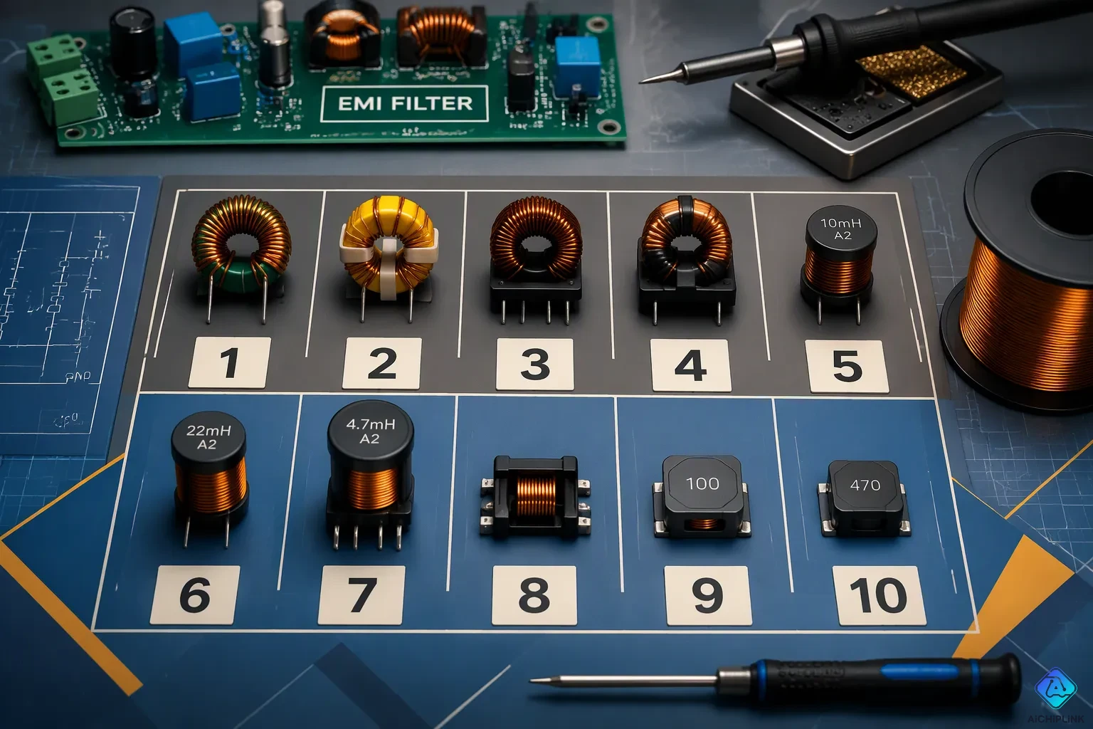
A common mode choke is a passive electromagnetic part that lets wanted differential signals pass but blocks common mode noise. This article compares 10 common mode chokes often used for EMI filtering, ranked by common use and construction style. Each entry covers construction, typical uses, key specs like impedance versus frequency, current rating, DCR, and insertion loss, plus selection trade-offs and a real part-family example. By the end, readers can match a choke's impedance curve to the noise frequency they need to suppress.
The Global Common Mode Chokes Market is worth $893.2 million in 2024 and is expected to grow at a CAGR of 6.7% from 2024 to 2030, reaching $1.32 billion by 2030.
Key Takeaways
-
Common mode chokes stop common mode noise and let differential signals through.
-
Match the choke's impedance curve to the noise frequency so the filter works well.
-
Think about current rating, saturation, and DCR to prevent signal loss and overheating.
-
Pick the right kind: ferrite to save money, nanocrystalline for top performance.
-
Put the choke close to the connector to block noise before it gets to sensitive circuits.
How Common Mode Chokes Work
Common Mode vs. Differential Mode Noise
Differential mode current goes out on one wire and comes back on the other. These two currents are the same in size but flow in opposite ways. Common mode current flows the same way on both lines and returns through ground or chassis. The telecommunications industry calls differential mode "normal mode" and common mode "longitudinal mode." ITU-T Recommendation K.10 defines common-mode current as the sum of the phasor currents in the active conductors. For an ideal two-conductor line, that sum equals zero. A sum that is not zero means current crosses the boundary by another path, like a shield or earth.
| Aspect | Common-Mode Interference | Differential-Mode Interference |
|---|---|---|
| Current direction | Same direction on both conductors | Opposite directions on the two conductors |
| Return path | Returns via ground | Returns via the signal return path |
| Typical source | Potentials between trace pair and PCB ground | Crosstalk between two PCB traces |
Key Specs for EMI Chokes
A common mode choke works as a current-compensated choke, basically a 1:1 current transformer. When equal currents flow in both windings, the part shows large series impedance and blocks common-mode current. Differential signals see only leakage inductance, so a coupled style with low leakage presents low impedance to wanted signals. A high-permeability ferrite or nanocrystalline core maximizes the series impedance for common-mode noise suppression. Using both windings together improves coupling, though it raises inter-winding capacitance and can degrade high-frequency filtering.
Readers compare five specs across all 10 types. Impedance versus frequency shows where the part suppresses noise. Current rating spans 0.06 A to 15 A. DCR sets resistive loss and heating. Common-mode insertion loss measures attenuation in dB. Physical size drives board layout and mounting choice. These five specs let an engineer match an EMI choke to a measured noise spectrum before committing to a design.
1. Toroidal Ferrite Core Chokes
Construction and Operating Principle
A toroidal ferrite core choke has two bifilar windings around a ring-shaped ferrite core. The two windings are side by side and share one magnetic path. This design gives high inductance in a small space and delivers strong common mode impedance over a wide band. The core material — often nickel-zinc or manganese-zinc ferrite — controls where that impedance peaks.
The coupled windings let differential signals through with almost no loss. But common-mode current moves the same way on both lines, so it meets a large series impedance. That difference is what blocks common-mode noise. Designers choose a ferrite grade with high permeability. This pushes up impedance at the noise frequencies they want to stop. A good match can make a noisy line quiet while leaving the signal alone.
Specs, Trade-Offs, and Example Part Family
These chokes work well in switch-mode power supply input filters, AC/DC power lines, and industrial equipment. They can handle currents from about 0.06 A to 15 A, based on wire gauge and core size. Important specs are impedance versus frequency, DCR, current rating, and insertion loss. A bigger core raises impedance but also adds cost, weight, and board space.
Trade-offs are important. High permeability helps low-frequency impedance, but it can lower the saturation threshold. Thicker wire reduces DCR and heat, yet fewer turns means less inductance. Engineers weigh these issues against the noise spectrum they must control. Common part families for this style include the TDK ACM series and the Wurth WE-SL series. Both are dependable EMI chokes for power and signal lines, and both show up often in EMI filters for industrial gear.
2. Nanocrystalline Core Chokes
Construction and Operating Principle
Nanocrystalline cores start as a thin glassy ribbon. The ribbon is wound into a core. This material is brittle and cracks easily, just like glass. Makers put the ribbon core inside a heat-resistant plastic case. Then they seal it, shake-test it, and drop-test it. The finished part is rugged enough for harsh places.
The core has high permeability, usually 20,000 to 200,000 μi. Some series offer 50,000 μi. Its saturation flux density reaches 1.25 Tesla. That is more than twice the value of ferrites, which stay below 0.5 Tesla. The core can hold more flux. These common mode chokes handle strong common mode currents without saturation. They block common-mode noise well in a small package. Differential signals pass through with almost no loss. Noise currents that flow the same way meet a large impedance.
Specs, Trade-Offs, and Example Part Family
Engineers put these parts in compact EMI filters that block a lot of noise, solar inverters, EV onboard chargers, and three-phase power systems. The high saturation limit helps military, aerospace, transportation, and medical equipment. These settings mix heat, vibration, and tight space.
| Attribute | Details |
|---|---|
| Core construction | Thin glassy ribbon coiled and sealed in a heat-resistant plastic case |
| Permeability | 20,000–200,000 μi; some series offer 50,000 μi |
| Saturation flux density | 1.25 T (ferrites less than 0.5 T) |
| Typical uses | Military, aerospace, transportation, medical, solar, wind, three-phase power |
This table shows why a designer might pick a nanocrystalline part. Higher flux density lets the part keep its impedance under DC bias. That steady behavior gives consistent insertion loss across the full current range. The main downside is cost. These parts cost more than ferrite designs. They also need more steps to build.
The VAC VITROPERM-based parts and the Schaffner FN series are proven part families. Both give reliable EMI choke performance for demanding systems. For engineers choosing EMI chokes, these parts give the highest attenuation per volume. One small unit can replace a much larger ferrite part. That advantage matters when board space is tight and interference is severe.
3. SMD Wire-Wound Chip Chokes
Construction and Operating Principle
A small ferrite drum or toroid makes up the core. A maker wraps copper wire around the core and adds SMD ends. The two windings share one magnetic path. Differential signals go through with almost no resistance. Common-mode noise hits high impedance and cannot pass. This principle explains why the part matters in modern circuit boards.
The compact body works with automated assembly. Pick-and-place machines handle these parts fast. Portable electronics gain from the low profile. The ferrite makeup sets the frequency of peak impedance. Designers pick a core that matches the interference they must block. A poor match causes weak filtering.
Specs, Trade-Offs, and Example Part Family
Engineers use SMD wire-wound parts in DC-DC converters, USB and HDMI data lines, and portable gear. These uses need low DCR and stable impedance curves. The component should block unwanted signals while keeping data integrity. Differential signals face only leakage inductance, so data quality stays high. Board space becomes a key factor in every layout.
Saturation behavior needs close attention. A small core saturates fast under high DC bias. Once saturated, the component stops filtering. This trade-off limits the usable current range. Smaller packages also limit wire gauge. Thicker wire lowers DCR but needs more space. A designer can predict this behavior from the datasheet curve. Picking a larger package can ease this limit.
The Murata DLW series and TDK ACM-V series are proven part families. Each family gives multiple impedance and size options. These common mode chokes fit tight layouts where through-hole parts cannot go. They do excellent common-mode noise suppression on signal and power lines.
When comparing EMI chokes, engineers study insertion loss over the target band. They also compare DCR and current ratings. Placement near the connector improves performance. Many EMI filters depend on this component as the first line of defense. This common mode choke style balances size, cost, and attenuation well.
4. Multilayer Chip Common Mode Chokes
Construction and Operating Principle
This part stacks thin ferrite layers on top of each other. Every layer has a printed coil pattern on it. Plated vias link those patterns into two coupled windings. This way, a full common mode choke is built inside a tiny flat body. The finished part takes up a small share of the board space that a wire-wound toroid needs. Mobile devices gain from this because space is hard to find.
The stacked ferrite makes a closed magnetic path. Differential signals only see leakage inductance. They go through without much attenuation. The coupled windings make a high series impedance for common-mode noise. The ferrite mix sets the impedance peak. Designers choose a material grade that fits the target frequency band. The printed patterns can be tuned while they are made, which gives exact impedance values. The part acts like a bigger wound component, but it comes in a package small enough for tight layouts.
Specs, Trade-Offs, and Example Part Family
These common mode chokes work well in high-speed PCBs, mobile devices, and differential signal lines. They fit under processors, next to connectors, and inside power stages. Many designers use them in small EMI filters where board space is limited. The tiny footprint also lets several channels sit on one board. The low profile fits under shielding cans.
Multilayer chokes keep stable impedance across a wide frequency range. Printed coil patterns cut down parasitic capacitance, which pushes useful suppression into higher bands. The main trade-off is current handling. A small chip saturates fast under high dc bias. Once it saturates, the part stops giving attenuation. Engineers must lay the impedance-versus-frequency curve over the targeted spectrum. A network analyzer measures the real insertion loss after assembly. They should also check DCR and current rating before they finalize the layout.
Murata DLP series and TDK MCZ series are common picks in this group. Both families give many impedance and package options. Their flat bodies work well with automated assembly and high-volume production. These parts add little inductance to a differential pair, so they keep signal edges on USB, HDMI, or MIPI lines. That mix of size and signal integrity makes them a strong choice for portable electronics.
5. High-Current Power Line Chokes
Construction and Operating Principle
A high-current power line choke has two matching windings on one shared toroidal or E-core. The windings are placed so differential working current goes through them in opposite directions. The magnetic fluxes from these opposing currents are equal and opposite, so they almost cancel inside the core. The differential current then only sees the small leakage inductance and winding resistance. Since the net working flux stays near zero, the core can use very high permeability material like MnZn ferrite, nanocrystalline, or amorphous tape without saturating, even at high current. That same high permeability creates strong common mode impedance. When common-mode current flows, it enters both windings in the same direction, so the fluxes add up and the choke works as a high-value inductor in series with each conductor.
These parts come in large toroidal or bobbin-wound styles rated up to 15 A and beyond. A typical vertical mount toroidal common mode choke coil uses a Mn-Zn ferrite toroid with a green epoxy coating for mechanical protection and reinforced insulation. Two different wire colors make it easy to identify polarity. A flame retardant 4-pin plastic base keeps the core stable under vibration and holds a consistent standoff height for wave soldering and creepage distance.
Specs, Trade-Offs, and Example Part Family
| Application | Rated Current | CM Inductance | Core Type | DCR / winding |
|---|---|---|---|---|
| Compact SMPS / adapter | 1 to 3 A | 10 to 47 mH | MnZn toroid | 0.1 to 0.5 Ω |
| Appliance / IT equipment | 4 to 10 A | 1 to 10 mH | MnZn / nanocrystalline | 20 to 80 mΩ |
| Industrial drive input | 10 to 30 A | 0.5 to 5 mH | Nanocrystalline | 5 to 20 mΩ |
| EV charger / 3-phase | 30 to 60+ A | 0.1 to 2 mH | Nanocrystalline / amorphous | 1 to 8 mΩ |
Engineers use these common mode chokes in SMPS, motor drives, and server power supplies. Key specs include common mode inductance from 0.5 mH to 100 mH, rated current from 0.3 A to 20 A, and DCR from 5 mΩ to 2000 Ω per winding at 20 degC. Leakage inductance runs about 0.5% to 2% of the common mode value. Dielectric withstanding voltage reaches AC 1500 V to 3000 V for one minute. The main trade-off is size versus current: thicker wire lowers DCR but needs a larger core. The Schaffner FN 20xx series and Wurth WE-CMB series are proven part families for these emi filters.
6. Signal and Data Line Chokes
Construction and Operating Principle
Signal and data line chokes use small ferrite cores with thin wire windings. These parts handle low currents, sometimes as low as 0.06 A. The design focuses on keeping signals clear rather than handling power. A tiny core keeps parasitic capacitance low. This lets high-speed data pass through without distortion. The coupled windings block common-mode noise while differential signals move freely. Engineers pick these chokes when a data line needs protection from interference without slowing the signal.
These components serve CAN, RS-485, Ethernet, and USB data lines. Each protocol has its own noise pattern. A choke with the right impedance curve suppresses that noise. The part sits close to the connector. This placement stops interference before it reaches sensitive circuits. Many emi filters for data ports rely on this style of choke as the first defense.
Specs, Trade-Offs, and Example Part Family
The Murata DLW21 series shows what a data line common mode choke can do. It handles two lines with an impedance of 90 Ohms at 100 MHz. The current rating reaches 330 mA. Its DCR stays at 350 mOhm. The part works from -40°C to 85°C and mounts on a surface pad. Its body measures just 2.00 mm by 1.20 mm.
| Parameter | Value |
|---|---|
| Impedance @ 100 MHz | 90 Ohms |
| Current Rating (Max) | 330 mA |
| DCR (Max) | 350 mOhm |
| Operating Temperature | -40°C to 85°C |
| Size | 2.00 mm x 1.20 mm |
Designers face a trade-off between impedance and current capacity. A higher impedance blocks more common-mode noise but may add DCR. That resistance can degrade signal quality on long lines. The Wurth WE-SL series and Murata DLW21H series are proven part families. Specific part numbers include DLW21SN900SQ2L and DLW21SN900HQ2L. These chokes give reliable suppression for data line common mode chokes in compact designs.
7. Automotive-Grade Common Mode Chokes
Construction and Operating Principle
Parts made for cars must handle tough environments. The AEC-Q200 standard sets the test bar for passive parts in vehicles. Common mode chokes with this certification pass strict reliability checks. They can handle big temperature changes and strong vibration.
The Vishay Dale ICMS2321-1A shows one way to build these parts. Its small, low-profile body takes up less space on the board. That smaller size makes the part resist shock and vibration better. A tough, self-shielded case guards the windings from stress. Many automotive chokes follow the same design ideas.
The improved core design keeps working well at high heat. This part can run up to +150 °C and still hold its saturation current. Standard commercial parts often get weaker at that temperature. The coupled windings act like other common mode designs. Differential signals pass with little loss, but common-mode noise meets high series impedance. The part blocks that noise completely. The core holds enough magnetic flux to keep working when hot.
Specs, Trade-Offs, and Example Part Family
These parts are used in EV powertrains, ADAS sensors, infotainment systems, and CAN or LIN buses. On-board charger EMI filters rely on this component.
| Specification | Commercial Grade (ICMS2321-10) | Automotive Grade (ICMS2321-1A) |
|---|---|---|
| Maximum operating temperature | +150 °C | +150 °C |
| AEC-Q200 qualification | No | Yes |
Both grades share the same top temperature. The real difference is AEC-Q200 qualification. The automotive grade passes tests for temperature cycling, vibration, and mechanical shock. The commercial grade does not have that qualification. Certification raises the cost. Engineers weigh that cost against the risk of failure in the field.
The TDK ACM-A series and Murata DLW-A series are proven part families. Each family offers many inductance and current choices. The low profile fits into cramped automotive enclosures. Designers compare the impedance curve to the measured noise spectrum. The best part is the one with the strongest rejection at the problem frequency.
Their low-profile bodies are smaller and lighter, so they resist shock and vibration better. The improved core design boosts performance and saturation current at temperatures up to +150 °C.
The smaller body uses less board space. The self-shielded build keeps magnetic flux inside. This protects nearby circuits from noise. These parts survive engine heat and rough roads. They keep filtering even when standard parts give out.
8. Three-Phase Common Mode Chokes
Three-phase common mode chokes use one shared core for three windings. Each winding handles one phase of a three-phase AC line. The core links all three windings magnetically. In normal operation, the phase currents add to zero. Their fluxes cancel inside the core. So the choke gives low impedance to the differential power flow.
Construction and Operating Principle
When currents on all three lines flow the same way, common-mode interference occurs. These currents go back through ground or chassis. The three fluxes join together. The core feels a strong magnetic field. The choke offers high series impedance to that noise. That is why the three-winding design stays compact. One part handles all three phases instead of three separate parts.
Specs, Trade-Offs, and Example Part Family
These chokes support motor drives, industrial inverters, and three-phase EMI filters. A common part uses a toroidal or E-core made from high-permeability material. Many designs rely on nanocrystalline cores. These cores take high flux without saturating. Their saturation flux density is more than twice that of ferrite. That margin lets the choke keep working on heavy load transients.
Key specs are common mode inductance, rated current, DCR, and leakage inductance. Engineers compare the impedance curve with the measured noise spectrum. They also check heat rise at full load. A larger core cuts DCR but adds weight. Higher inductance blocks low-frequency noise better but can reduce current handling.
The trade-offs are similar to single-phase power line designs. Leakage inductance affects differential-mode filtering. The winding layout and core shape decide that value. Mechanical layout matters too. The choke must keep creepage distances between phases to pass safety standards.
The Schaffner FN 33xx series and Wurth WE-CMB three-phase family are proven options. These parts fit well into three-phase input stages. Designers put them after the input connector and before the rectifier. That position stops unwanted common-mode currents from reaching sensitive circuits.
To pick the right part, you need a measured spectrum. An engineer compares the choke's impedance curve with that data. The best choice shows its peak impedance at the problem frequency. That match works the best.
9. Integrated EMI Filter Chokes
Construction and Operating Principle
An integrated module puts a wound choke, X capacitors, and Y capacitors together inside one case. The X capacitor sits across the two power wires. It soaks up differential-mode interference. The Y capacitors connect from each wire to ground. They push in-phase currents away from the protected circuit. The choke adds strong resistance to that same unwanted current. All these parts work together to make a full common-mode emi filter.
Inside, the choke sits between the power inlet and the capacitor network. This two-step design cleans the incoming AC power in order. First, the capacitors move part of the noise energy aside. Then, the choke blocks the current that is left. Engineers put the module right at the AC power inlet. That spot stops noise from moving deeper into the system. This fixed order also keeps wires tidy.
Specs, Trade-Offs, and Example Part Family
Integrated common mode filter chokes are used in AC/DC power entry stages, medical equipment, and telecom rectifiers. Medical gear needs low leakage current, so the Y capacitor values stay small. Telecom systems need even attenuation over a wide frequency range. One module handles both needs without extra parts. These common mode chokes also cut assembly time because one part takes the place of many separate ones.
The downside is less flexibility. A discrete choke lets engineers adjust inductance and capacitance on their own. An integrated module sets those values at the factory. If one value misses the noise spectrum you need, the whole module must be replaced. The module also costs more than a single choke. But integrated emi filters make the board layout easier. They also create a cleaner layout and lower the number of solder joints. The Schaffner FN 92xx series and TE Corcom series are proven choices. Each family gives many current and attenuation ratings. Designers place the datasheet impedance curve over the measured noise profile. The module with the best blocking at the problem frequency wins.
10. High-Frequency Broadband Chokes
Construction and Operating Principle
High-frequency broadband chokes use thin wire wrapped around a small ferrite core. This core material has lower permeability than power-line types. That choice cuts parasitic capacitance and pushes the impedance peak up into the gigahertz range. The coupled windings block common-mode current over a wide band. Differential signals pass through with almost no loss. This wide bandwidth sets these parts apart from narrowband chokes that only block a small frequency slice.
Engineers use these chokes on high-speed PCBs, RF circuits, and HDMI or USB 3.x lines. One part can block high-frequency noise from several sources at the same time. The small body fits close to connectors and under shields. Many emi filters for data ports count on this style as the first line of defense.
Specs, Trade-Offs, and Example Part Family
The TDK MCZ0806DH900L2TA0G shows what this class can do. It belongs to the 90-ohm impedance class. Its typical differential-mode attenuation stays below 0.5 dB up to 8 GHz. That low loss matters for PCIe Gen3 signaling, where signal integrity is critical. Other parts in this group include the TCM0806G-900-2P-T200 and TCM0605G-900-2P-T200. The Würth Elektronik 744232090 and Coilcraft 0603USB-901MLC offer similar performance.
| Parameter | Value |
|---|---|
| Impedance class | 90 ohm |
| Differential-mode attenuation | Below 0.5 dB up to 8 GHz |
| Example part numbers | MCZ0806DH900L2TA0G; TCM0806G-900-2P-T200 |
Designers face a trade-off between bandwidth and current handling. A wider band often means a smaller core, which saturates faster under DC bias. The low DCR keeps signal loss small. Engineers overlay the impedance curve against the measured noise spectrum before selecting a part. The best choice peaks at the problem frequency without harming the data eye.
How to Choose the Right Common Mode Choke
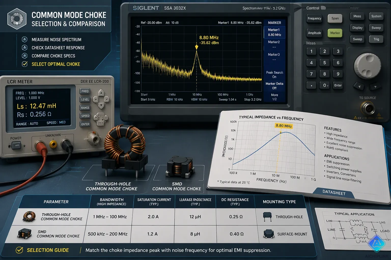
Engineers compare five things before they pick a part: bandwidth, saturation current, leakage inductance, DCR, and mounting type. Each one balances attenuation against circuit safety.
Matching Impedance Curve to Noise Frequency
The impedance curve has to line up with the target frequency. Common mode chokes often need high inductance to meet CISPR 22 limits below 500 kHz. But a large share of common-mode interference shows up in the upper range of 10 to 30 MHz. Not every ferrite keeps inductance at those frequencies. High-permeability materials narrow the bandwidth (Snoek's law). A high-inductance filter may look strong on paper yet fail at high frequencies.
The correct method is simple. Overlay the datasheet impedance-versus-frequency curve onto the measured spectrum. The best part shows its peak impedance at the problem frequency. Engineers should also remember that conducting bands placed close to a common-mode choke can change the attenuation of an entire common-mode emi filter. Placement matters as much as the part itself.
Saturation Current, Leakage Inductance, and Mounting Type
Saturation current must be higher than the circuit's peak current. Going past that limit makes common mode attenuation drop sharply, and the choke loses its ability to suppress noise. Leakage inductance runs about 1% to 3% of the common mode value. That small amount acts like an unwanted differential-mode inductor. For strong differential-mode filtering, designers add a separate differential-mode inductor.
DCR controls heat. The power loss equals I²R. Smaller packages use thinner wire, which pushes DCR up and lowers saturation current. Mounting type drives the first choice. Through-hole toroids handle heat and vibration well for power-line use. SMD parts fit automated assembly.
Power line emi filters must handle continuous high currents and prioritize saturation current and thermal performance. Data line systems focus on preserving signal integrity, requiring minimal differential mode impedance to avoid distorting waveforms.
The trade-off between current and impedance never goes away. Higher current needs thicker wire, which leaves room for fewer turns and lowers impedance. A nanocrystalline core offers high permeability, so fewer turns deliver the same impedance with lower DCR. Ferrite remains the economical choice for small SMD signal-line chokes and for high-frequency filters. Engineers weigh these factors together, shortlist two or three candidates, and bench-test them.
The best common mode choke is the one whose impedance peak and bandwidth match the noise frequency a designer needs to block — not just the part with the highest impedance. Before you lock in a part, weigh current rating, saturation behavior, leakage inductance, and mounting type together. Pull impedance-versus-frequency curves from datasheets and lay them over the measured or expected spectrum. Then pick two or three of the ten types and test them on the bench. A common-mode choke that looks strong on paper can fail once real conditions apply. Careful comparison of common mode chokes and their filters pays off at the bench.

Written by Jack Elliott from AIChipLink.
AIChipLink, one of the fastest-growing global independent electronic components distributors in the world, offers millions of products from thousands of manufacturers, and many of our in-stock parts is available to ship same day.
We mainly source and distribute integrated circuit (IC) products of brands such as Broadcom, Microchip, Texas Instruments, Infineon, NXP, Analog Devices, Qualcomm, Intel, etc., which are widely used in communication & network, telecom, industrial control, new energy and automotive electronics.
Empowered by AI, Linked to the Future. Get started on AIChipLink and submit your RFQ online today!
Frequently Asked Questions
What is the difference between common mode and differential mode noise?
Common mode noise travels the same way on both wires and comes back through ground. Differential mode noise travels in opposite ways on the two lines. A common mode choke stops the first kind but lets the second kind go through with very little loss.
How does a common mode choke suppress EMI?
The coupled windings create high impedance for common-mode current. Differential signals only see leakage inductance, so they pass through easily. This impedance difference blocks unwanted noise while keeping the wanted signal safe. Engineers match the impedance curve to the noise frequency to get the best result.
What specs matter most when selecting a choke?
Engineers compare impedance versus frequency, current rating, DCR, insertion loss, and physical size. Saturation current must be higher than the circuit's peak current. Leakage inductance is about 1% to 3% of the common mode value. Mounting type is the first choice between through-hole and SMD parts.
Can a choke handle both power and signal lines?
No. Power line chokes handle currents up to 15 A and focus on saturation current and heat performance. Signal line chokes handle currents as low as 0.06 A and focus on keeping signals clear. Each type fits its own use. Designers pick the style that matches their circuit needs.
Why does placement matter for EMI filters?
Conducting bands placed close to a common mode choke can change how much an entire common-mode EMI filter blocks. Engineers place the choke near the connector to stop interference before it reaches sensitive circuits. The datasheet impedance curve should be laid over the measured noise spectrum before the design is finalized.