Introduction
You've laid out your PCB, routed all the signal lines, passed functional testing — and then your design fails EMC pre-compliance. The radiated emissions plot shows a spike at 100 MHz you never accounted for. Sound familiar? It's one of the most frustrating moments in electronics engineering, and it happens to experienced designers all the time.
The good news: a single passive component placed strategically on your PCB can eliminate that spike before it ever becomes a problem. The BLA31AG102SN4D from Murata Manufacturing is a 4-circuit ferrite bead array delivering 1,000 Ω impedance at 100 MHz in a compact 1206 (3216 metric) footprint — filtering four signal or power lines simultaneously with a single component, saving board space and reducing your BOM line count.
According to IEC CISPR 32, the international standard governing electromagnetic emissions from multimedia equipment, high-frequency noise suppression at 30–300 MHz is mandatory for CE and FCC certification. A well-chosen ferrite bead array like the BLA31AG102SN4D is one of the most cost-effective tools in your EMC compliance toolkit.
In this complete guide, you'll find everything you need: full specifications, impedance behavior analysis, real-world application examples, head-to-head comparisons with competing parts, PCB layout guidance, and expert sourcing advice. Let's get into it.
1.0 What Is the BLA31AG102SN4D? An Overview
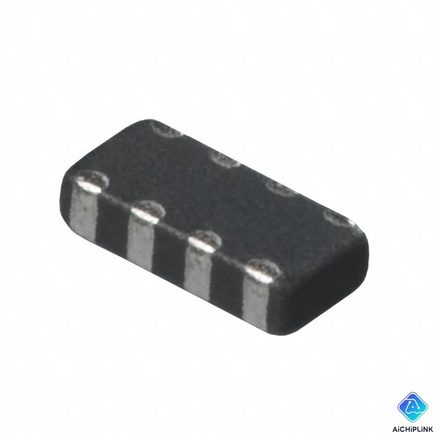
The BLA31AG102SN4D is a chip-type ferrite bead inductor array manufactured by Murata Manufacturing Co., Ltd. (Country of Origin: Japan). It belongs to Murata's BLA31A/B series — a family of high-performance EMI suppression filters that integrate four independent ferrite bead circuits into a single 1206-size SMD package.
Breaking down the part number reveals its full specification at a glance:
- BL — Chip Ferrite Bead (Murata product family ID)
- A — Array type (multiple circuits in one package)
- 31 — 1206 EIA size (3.2 mm × 1.6 mm body)
- A — Characteristics type: General use (broadband attenuation)
- G — Internal circuit configuration (4 independent circuits, 8-pad footprint)
- 102 — Impedance code: 1,000 Ω at 100 MHz (10 × 10² = 1000 Ω)
- SN — Termination: Sn (tin) over Ni (nickel) barrier — lead-free, RoHS compliant
- 4D — Packaging: Embossed tape, 4,000 pieces per reel
"Murata's BLA31A/B series arrays consolidate four ferrite bead circuits into the footprint of a single 1206 component, effectively quadrupling noise suppression density without increasing PCB area."
The key differentiator of this device over single-circuit ferrite beads is its 4-in-1 array construction. Where a standard design might require four discrete 0402 or 0603 ferrite beads to filter a 4-bit data bus, the BLA31AG102SN4D handles all four lines with one component — reducing pick-and-place time, solder joint count, placement error risk, and BOM complexity.
2.0 Full Technical Specifications & Electrical Characteristics
2.1 Core Electrical Parameters
Here is the complete specification summary from the BLA31AG102SN4D datasheet:
- Type: Chip Ferrite Bead Array (4 independent circuits)
- Impedance @ 100 MHz: 1,000 Ω (±25% tolerance)
- Impedance @ 1 MHz: ~10 Ω (predominantly inductive below resonance)
- Impedance @ 500 MHz: ~600–800 Ω (resistive-dominant above resonance)
- DC Resistance (Rdc): 450 mΩ maximum per circuit
- Rated DC Current: 50 mA per circuit
- Number of Circuits: 4 (electrically independent)
- Total Terminals: 8 pads (2 per circuit)
- Package / EIA Size: 1206 (3216 Metric)
- Body Dimensions: 3.2 mm (L) × 1.6 mm (W) × 0.8 mm (H)
- Operating Temperature: −55°C to +125°C
- Storage Temperature: −40°C to +85°C
- Electrode Termination: Sn/Ni barrier (lead-free, matte tin finish)
- RoHS Compliant: Yes — fully lead-free
- Country of Origin: Japan
- Packaging: Embossed carrier tape, 4,000 pcs/reel
- MSL: Not applicable (passive component, non-moisture-sensitive)
The ±25% impedance tolerance is standard for ferrite bead EMI filter applications and is not a precision specification issue — impedance variation of ±25% at 100 MHz has negligible impact on noise suppression effectiveness, since ferrite beads operate as broadband absorbers rather than tuned resonators.
2.2 Impedance vs. Frequency Behavior
Understanding the impedance-frequency curve is essential to using any ferrite bead correctly. The BLA31AG102SN4D exhibits three distinct operating regions:
1. Inductive region (< ~30 MHz): Impedance rises proportionally with frequency. The bead behaves like an inductor (low loss, low attenuation). This region is useful for filtering switching noise from power supplies.
2. Resonance / Peak region (~50–150 MHz): Impedance peaks near 1,000 Ω. This is the primary EMI suppression zone for the BLA31AG102SN4D — it provides maximum resistive (lossy) attenuation of common digital clock harmonics and RF interference in the 50–200 MHz range.
3. Capacitive / Resistive region (> ~200 MHz): Impedance begins to decline due to parasitic inter-winding capacitance. Attenuation becomes progressively less effective above 500 MHz.
Practical implication: The BLA31AG102SN4D is optimally positioned for filtering 100 MHz–class noise — such as harmonic emissions from 25 MHz, 33 MHz, or 50 MHz clocks, USB 2.0 switching transients, and I²C/SPI bus noise in the 10–200 MHz range. For GHz-band noise suppression (PCIe, USB 3.x, HDMI), consider Murata's BLM or NFM series designed for high-frequency operation.
2.3 DC Resistance, Current Rating & Thermal Limits
The 50 mA per circuit rated current is the most important parameter to check during design. Exceeding this limit causes:
- Magnetic saturation of the ferrite core, which collapses the impedance and eliminates noise filtering entirely
- Thermal stress on the solder joints and electrode terminations due to I²R heating
- Long-term reliability degradation of the ferrite material at elevated temperatures
At 50 mA through a 450 mΩ maximum DC resistance, the worst-case power dissipation per circuit is:
P = I² × R = (0.05)² × 0.45 = 1.125 mW per circuit
This is negligibly small, confirming the BLA31AG102SN4D is a low-dissipation passive component with no thermal management requirements under rated conditions. However, if your circuit exceeds 50 mA per line — common in power rail filtering or high-drive GPIO applications — you must select a higher-current ferrite bead or use the BLA31BD series rated for higher current.
The −55°C to +125°C operating temperature range qualifies this component for automotive-adjacent, industrial, and harsh-environment applications, though the "G" characteristics suffix indicates this is a general-use (non-automotive-qualified, non-AEC-Q200) part.
2.4 Package Dimensions and Electrode Structure
The 1206 (3216 metric) body measures 3.2 mm × 1.6 mm × 0.8 mm — an industry-standard footprint that every PCB manufacturer and assembly house supports with confidence. The 8-pad layout (2 pads per circuit, 4 circuits) follows a standard symmetrical pitch.
The nickel (Ni) barrier electrode structure is a critical reliability feature. In standard tin-plated components without a nickel barrier, aggressive solder flux or extended reflow exposure can cause tin leaching into the ferrite body, degrading the electrode bond. The Ni barrier in the BLA31AG102SN4D prevents this, delivering:
- Excellent solder heat resistance during reflow and wave soldering
- Compatibility with both reflow and flow soldering assembly processes
- Long-term solder joint reliability under thermal cycling (−40°C to +85°C ΔT cycling)
3.0 EMI Suppression Applications
3.1 Power Line Noise Filtering
One of the most common applications for the BLA31AG102SN4D is power supply decoupling enhancement — placing the array in series with VCC power rails feeding noise-sensitive analog or mixed-signal circuitry. A typical configuration uses one ferrite bead circuit per supply rail, with bypass capacitors placed on the downstream (quiet) side of the bead:
- Ferrite bead (series): BLA31AG102SN4D circuit 1 in series with VCC_ANALOG
- Bulk capacitor (shunt): 10 μF electrolytic or ceramic downstream of bead
- High-frequency bypass (shunt): 100 nF X7R ceramic downstream of bead
This LC-like filter topology creates a low-pass characteristic: low-frequency DC passes unimpeded, while switching noise from the digital supply domain is absorbed by the ferrite bead's resistive impedance above its resonant frequency.
Important design note: The BLA31AG102SN4D's 50 mA per circuit current limit makes it appropriate for low-current analog supply rails (op-amp reference voltages, ADC AVCC, sensor power rails) but not for main digital VCC rails supplying FPGAs, processors, or high-drive I/O banks that may draw hundreds of milliamps. For higher-current power rail filtering, use Murata's BLM series (BLM31PG, BLM41PG) which support 1 A to 6 A ratings.
3.2 Multi-Line Signal Filtering: USB, I²C, SPI, and GPIO
The four-circuit array architecture makes the BLA31AG102SN4D ideal for data bus EMI filtering — a single component cleans up all signal lines of a 4-bit interface simultaneously:
USB 2.0 D+/D− filtering: Place one circuit of the BLA31AG102SN4D on each of D+ and D−, upstream of the USB connector ESD protection diodes. Use the remaining two circuits on VBUS and ID lines. The 1 kΩ impedance at 100 MHz attenuates common-mode noise without introducing significant differential-mode signal distortion at USB 2.0's 480 Mbps signaling rate — important caveat: verify signal integrity via simulation or eye diagram measurement when filtering high-speed differential lines, since ferrite impedance does affect signal rise time.
I²C bus filtering (SCL + SDA): I²C operates at 100 kHz to 1 MHz standard/fast mode — well below the BLA31AG102SN4D's resonant frequency. Placing one circuit per line suppresses conducted interference that would otherwise couple into nearby sensitive circuits, with negligible impact on signal integrity at I²C data rates.
4-bit GPIO or address bus: For microcontroller GPIO expanders, LED drivers, or address decoders where four output lines need simultaneous EMI filtering, the BLA31AG102SN4D allows all four lines to be filtered with a single BOM entry and one placement operation.
The video above covers Murata's ferrite bead selection process, impedance curve interpretation, and practical placement guidelines for achieving FCC/CE compliance in digital equipment designs.
4.0 BLA31AG102SN4D vs. Competing Ferrite Bead Arrays
How does the BLA31AG102SN4D compare to its closest alternatives within the Murata BLA31 family and competing manufacturers' products?
| Feature | BLA31AG102SN4D | BLA31BD471SN4D | BLA31BD601SN4D | TDK MEM2012P102T |
|---|---|---|---|---|
| Manufacturer | Murata | Murata | Murata | TDK |
| Impedance @ 100 MHz | 1,000 Ω | 470 Ω | 600 Ω | 1,000 Ω |
| Characteristics Type | A (General use) | B (High-speed signal) | B (High-speed signal) | General use |
| Rated DC Current | 50 mA / circuit | 100 mA / circuit | 100 mA / circuit | 100 mA / circuit |
| DC Resistance (max) | 450 mΩ | 300 mΩ | 350 mΩ | 400 mΩ |
| Number of Circuits | 4 | 4 | 4 | 4 |
| Package | 1206 (3216M) | 1206 (3216M) | 1206 (3216M) | 0805 (2012M) |
| Operating Temp. | −55°C to +125°C | −55°C to +125°C | −55°C to +125°C | −25°C to +85°C |
| RoHS | Yes | Yes | Yes | Yes |
4.1 BLA31AG102SN4D vs. BLA31BD Series: Which to Choose?
The most frequent selection question engineers face is whether to use the BLA31AG (General-use) or BLA31BD (High-speed signal) series. Here's the practical guidance:
Choose BLA31AG102SN4D when:
- Your signal lines carry DC or low-frequency data (I²C ≤ 1 MHz, SPI ≤ 10 MHz, GPIO, LED)
- You need maximum impedance at 100 MHz (1,000 Ω) for aggressive noise suppression
- Current per line is 50 mA or below
- Your application is power rail filtering for analog or mixed-signal supplies
Choose BLA31BD series when:
- Your signal lines carry high-speed differential or single-ended data (USB 2.0 HS, Fast Ethernet, 50+ Mbps interfaces)
- You need lower DC resistance and higher current rating (100 mA per circuit)
- Signal integrity is more critical than maximum attenuation magnitude
- The "B" characteristics provide a flatter impedance curve more suited to broadband high-speed filtering
The fundamental trade-off: "A" characteristics optimize for peak impedance magnitude at 100 MHz (1,000 Ω — maximum noise kill). "B" characteristics optimize for current handling and signal integrity at the expense of some peak attenuation.
4.2 Pricing, Availability & RoHS Status
The BLA31AG102SN4D is an active production part with broad distributor availability:
- Authorized distributors: DigiKey, Mouser, Arrow, RS Components, TME — all carry stock in reel (4,000 pcs) and cut-tape quantities
- Typical unit price (volume): ~$0.05–$0.12 USD at 1,000+ pieces depending on distributor and market conditions
- Lead time: Standard stock item — typically ships same day or next day from authorized distributors
- RoHS status: Fully compliant — tin-over-nickel (Sn/Ni) termination, no restricted substances
- Country of Origin: Japan (Murata manufacturing)
- ECCN: EAR99 (no export license required for most destinations)
For competitive pricing, verified authenticity, and volume procurement support, visit aichiplink.com — BLA31AG102SN4D listing.
5.0 PCB Design, Layout & Assembly Guidelines
5.1 PCB Placement and Routing Best Practices
Proper placement and routing is as important as component selection for achieving effective EMI suppression:
- Place as close to the noise source or entry point as possible. For connector-adjacent filtering, place the BLA31AG102SN4D within 2–3 mm of the connector body — before any trace routing that could act as an antenna.
- Place bypass capacitors on the quiet (downstream) side of the bead. The capacitor shunts high-frequency noise to ground after it has been absorbed by the bead's resistive impedance — the order matters.
- Keep the noisy (upstream) and quiet (downstream) traces physically separated. If noisy and filtered traces run parallel for more than 5 mm, capacitive coupling will re-inject noise past the filter.
- Avoid crossing noisy signals over filtered signal traces on adjacent layers — use a ground plane layer between signal layers to provide isolation.
- Do not place the ferrite bead array near high-current power traces or transformers — the magnetic field from these sources can partially saturate the ferrite core and degrade impedance.
- Use the recommended 1206 SMD land pattern from Murata's datasheet: pad size 1.7 mm × 1.5 mm per pad, with 0.5 mm gap between pads. This optimizes solder joint reliability and minimizes tombstoning risk during reflow.
5.2 Reflow Soldering and Electrode Reliability
The BLA31AG102SN4D's nickel barrier electrode is engineered for both reflow and flow soldering compatibility:
Reflow profile (recommended):
- Preheat: 150–200°C for 60–120 seconds
- Peak reflow temperature: ≤ 260°C (Sn-Ag-Cu lead-free solder paste recommended)
- Time above 220°C: ≤ 30 seconds
- Cooling rate: ≤ 4°C/second (gradual cool to prevent thermal shock)
Rework guidance:
- Use hot-air rework at ≤ 300°C nozzle temperature; limit exposure time to ≤ 10 seconds
- Do not use soldering iron directly on the ceramic body — thermal shock can crack the ferrite substrate
- Allow component to cool to room temperature before re-inspection under magnification
Moisture sensitivity: Ferrite bead arrays are not moisture-sensitive (not classified under IPC/JEDEC J-STD-020) and require no bake-out before assembly. Components stored in original tape-on-reel packaging can be used directly from the reel without pre-conditioning.
For verified authentic BLA31AG102SN4D stock with original Murata tape-and-reel packaging, visit aichiplink.com for competitive pricing and fast global fulfillment.
6.0 How to Source Authentic BLA31AG102SN4D Units
While the BLA31AG102SN4D is a relatively low-cost passive component, counterfeit and substandard ferrite beads are more common in the secondary market than engineers typically expect. A counterfeit bead may have the correct physical dimensions and pass a basic continuity check yet deliver only a fraction of the specified 1 kΩ impedance at 100 MHz — completely defeating its purpose.
Here's how to protect your supply chain:
- Purchase from authorized distributors only: DigiKey, Mouser, Arrow, and RS Components are Murata's authorized stocking distributors for North America and Europe. Pricing from these channels is competitive and traceability is guaranteed.
- Verify the tape-and-reel labeling: Genuine Murata reels have a printed label showing the part number (BLA31AG102SN4D), Murata logo, lot code, quantity, and country of origin (Japan). Labels should be crisp and machine-printed — not handwritten or affixed over original labels.
- Electrical verification: Use an impedance analyzer (Keysight E4990A or equivalent) to measure impedance at 100 MHz on a sample. Genuine parts will read 750 Ω to 1,250 Ω (1,000 Ω ±25%). Values outside this range indicate substandard or counterfeit material.
- Request a Certificate of Conformance (CoC): For production procurement from any non-authorized source, demand a CoC and lot traceability documentation before accepting shipment.
For verified original Murata stock, full documentation, and expert support for both sample and volume orders, visit aichiplink.com — BLA31AG102SN4D.
8.0 Conclusion
The BLA31AG102SN4D delivers an elegant, cost-effective solution to one of PCB design's most persistent challenges: filtering high-frequency EMI across multiple signal or power lines without consuming excessive board space or complicating your BOM. Its 1,000 Ω impedance at 100 MHz, four independent circuits in a single 1206 footprint, nickel barrier electrodes for solder reliability, and −55°C to +125°C operating range make it one of the most versatile passive EMI suppression components in Murata's extensive lineup.
Whether you're filtering USB bus lines ahead of an ESD diode array, suppressing switching noise on a sensitive analog supply rail, or cleaning up GPIO emissions to pass FCC/CE pre-compliance testing, the BLA31AG102SN4D belongs in your passive component toolkit — and given its sub-$0.10 unit cost at volume, there's rarely a reason not to include it in your design.
As digital systems push ever-higher clock speeds and tighter EMC margins, the role of compact, high-performance passive filters like this one will only grow. Murata's long track record as the inventor of the chip ferrite bead and their continued active production commitment means the BLA31AG102SN4D will be a stable, supportable component choice for years to come.
Ready to order? Explore verified stock, competitive pricing, and expert procurement support for the BLA31AG102SN4D at aichiplink.com — with original Murata tape-and-reel packaging, full traceability, and fast global fulfillment.

Written by Jack Elliott from AIChipLink.
AIChipLink, one of the fastest-growing global independent electronic components distributors in the world, offers millions of products from thousands of manufacturers, and many of our in-stock parts is available to ship same day.
We mainly source and distribute integrated circuit (IC) products of brands such as Broadcom, Microchip, Texas Instruments, Infineon, NXP, Analog Devices, Qualcomm, Intel, etc., which are widely used in communication & network, telecom, industrial control, new energy and automotive electronics.
Empowered by AI, Linked to the Future. Get started on AIChipLink.com and submit your RFQ online today!
Frequently Asked Questions
What is the difference between BLA31AG102SN4D “A” and BLA31BD “B” types?
The “A” type provides higher peak impedance around 100 MHz for better noise suppression on low-speed lines and power rails, while the “B” type offers a flatter impedance curve for high-speed signal lines and improved signal integrity.
Can BLA31AG102SN4D be used on 3.3 V or 5 V power rails?
Yes, it can be used on both 3.3 V and 5 V rails as long as the current per circuit does not exceed 50 mA.
Is BLA31AG102SN4D suitable for common-mode noise filtering?
No, it is only for differential-mode noise; common-mode noise requires a common-mode choke from Murata Manufacturing.
How many channels does BLA31AG102SN4D contain?
It integrates four fully independent ferrite bead circuits in one package.
Can BLA31AG102SN4D be used in automotive applications?
It supports −55 °C to +125 °C operation, but it is not AEC-Q200 qualified, so it is not recommended for certified automotive designs.