What is a Thyristor?
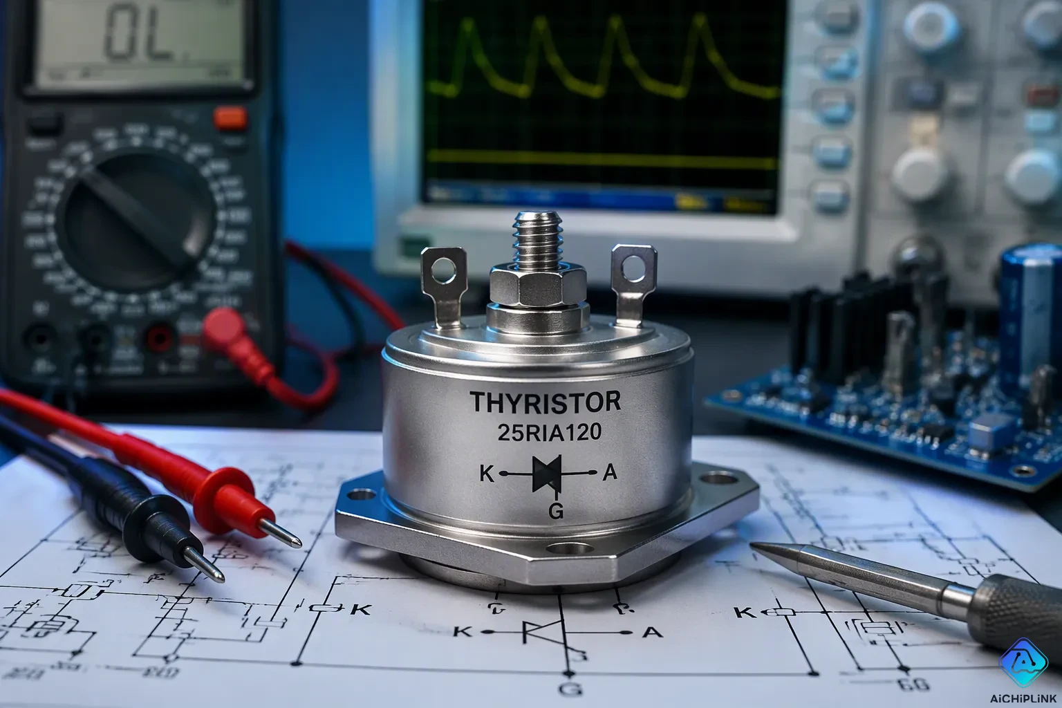
A thyristor is a four-layer solid-state semiconductor device. It has three electrodes: the anode, the cathode, and the gate. Three PN junctions sit in series inside this structure. You use a thyristor as a bistable switch. It controls high power with a small gate signal. Engineers also call it a silicon-controlled rectifier, or SCR.
This tiny component plays a big role in global electronics. The worldwide thyristor market reached USD 1.54 billion in 2024. It should grow to USD 2.35 billion by 2035.
The Global Thyristor Market size was valued at USD 1,350.00 million in 2018 to USD 1,521.77 million in 2024 and is anticipated to reach USD 2,172.33 million by 2032, at a CAGR of 4.62% during the forecast period.
Metric Value Global Thyristor Market Size (2024) USD 1.54 Billion CAGR (2025–2035) ~3.92% Projected Market Size (2035) USD 2.35 Billion
Key Takeaways
-
A thyristor is a four-layer semiconductor switch. It controls high power with a small gate signal.
-
A gate pulse turns the thyristor on and keeps it on. To turn it off, the current must drop below the holding current.
-
Thyristors have three modes: forward conducting, forward blocking, and reverse blocking.
-
Thyristors deal with high voltages and currents. They work well in motor drives and power converters.
Working Principle of Thyristor
Structure and Electrodes
The working principle of thyristor operation starts with its internal construction. A four-layer semiconductor forms the core of the device. These layers alternate between P-type and N-type material, creating a PNPN stack. Three PN junctions sit in series within this stack. Each junction acts as a one-way door for electrical current.
Three electrodes connect to this structure. The anode attaches to the outer P-layer. The cathode connects to the outer N-layer. The gate terminal in a thyristor links to the inner P-layer near the cathode. You apply a small signal at the gate terminal in a thyristor to control a much larger current path between the anode and cathode.
Engineers often model this PNPN stack as two coupled transistors. A PNP transistor and an NPN transistor connect in a regenerative feedback loop. Here is how that loop triggers conduction:
-
A gate current triggers the NPN transistor.
-
Its collector current provides base drive to the PNP transistor.
-
The PNP collector current then reinforces the base of the NPN transistor.
-
This positive feedback rapidly drives both transistors into saturation.
This internal loop sustains anode current even after you remove the gate signal. The device remains latched as a result.
The positive feedback inherent in the two-transistor model explains why the SCR continues to conduct after the gate pulse is removed. The anode current must be reduced below the holding current by circuit means, through natural current zero crossing in AC systems or forced commutation in DC systems, to turn the device off.
Latching and Holding Current
Once latched, a thyristor maintains conduction even after the gate signal disappears. This behavior continues as long as anode current exceeds the holding current. The device returns to its off state only when the supply voltage is removed or the load current falls below the holding current. This demonstrates the latching capability of an SCR.
Two current thresholds govern this behavior. The latching current is the minimum anode current that must be reached so the device stays conducting after you remove the gate signal. The holding current is the minimum anode current below which the device stops conducting and returns to the off state. The latching current is always higher than the holding current. It is generally about 2 to 3 times the holding current.
| Aspect | Latching Current | Holding Current |
|---|---|---|
| Related process | Turn-on process | Turn-off process |
| Definition | Minimum anode current to stay conducting after gate removal | Minimum anode current below which the device stops conducting |
| Relative magnitude | Higher than holding current | Lower than latching current |
| Typical ratio | About 2 to 3 times the holding current | — |
You control large currents with small control currents through this mechanism. A brief gate pulse latches the device on. The internal feedback loop then takes over. This makes a thyristor a powerful switch for high-power circuits. Different types of thyristors share this same basic working principle of thyristor operation.
Thyristor's Three Working Modes
A thyristor works in one of three clear states. These states depend on the voltage direction across its terminals and the gate signal. Knowing thyristor's three working modes helps you guess how the device acts in any circuit.
| Operating Mode | Description |
|---|---|
| Forward conducting | Main mode; keeps conducting until current falls below the holding current. |
| Forward blocking | Stops current flow even when forward voltage is applied. |
| Reverse blocking | Stops current trying to flow backward; thyristor is not turned on. |
Forward Conducting Mode
You enter this mode when the anode is positive compared to the cathode. Two paths lead here. You can raise the anode voltage past the breakover value. Avalanche breakdown then happens at the reverse-biased junction. Large current flows, and the device turns on no matter the gate voltage. Or you apply a positive gate voltage. This adds current that lowers the anode-to-cathode voltage needed for breakdown. Conduction starts below the breakover value.
Here is the normal triggering sequence:
-
Connect the positive supply terminal to the anode and the negative terminal to the cathode, with the gate circuit closed.
-
Apply a gate signal for a short time of latching current.
-
Make sure the anode current reaches the latching current value; once reached, the gate loses control and you can remove it.
-
Keep anode current above the holding current to hold the thyristor in forward conduction; if it falls below holding current, the thyristor goes back to forward blocking mode.
Once conducting, the gate loses control. The internal positive feedback loop keeps the current path going. The device latches permanently on. A thyristor acts as a one-way device here. Current flows from anode to cathode only.
Other trigger methods exist. Light activation works in light-activated SCRs. A quickly rising anode voltage can also trigger conduction through internal capacitances. You must keep this rate below set limits to avoid unwanted turn-on.
Forward and Reverse Blocking Modes
In forward blocking mode, no gate signal reaches the device. The thyristor stays off. No current flows no matter the anode voltage. The device holds off positive bias until the gate gets a signal or the breakover voltage is passed. Off-state currents, such as IDRM and IRRM, stay very small. Manufacturers set these at maximum off-state voltages VDRM and VRRM.
Reverse blocking mode happens when you reverse the polarity. The anode is negative compared to the cathode. The thyristor blocks current in this direction. No gate signal can turn it on. This behavior is like a simple diode.
The device is bistable. It exists only in on or off states. Each state stays stable without active triggering. You do not need to hold a gate signal to keep the thyristor conducting. You must lower anode current below the holding current to turn it off. This latching behavior sets a thyristor apart from other types of thyristors and from linear devices. The switch stays where you put it.
Applications of Thyristor
Power Control and Motor Drives
You use a thyristor to control power in factory systems. One common use is the soft starter for big motors. When a motor starts, it can pull a large inrush current. This surge puts stress on both the motor and the power grid. A soft starter uses thyristors to limit it.
The soft starter fires the SCRs at a set angle. This limits the inrush current. The control circuit watches the current draw. It adjusts voltage to keep current in safe limits. As the motor speeds up, voltage rises slowly. A bypass contactor takes over at full speed. You can also use this for a soft stop.
Thyristors also work in variable frequency drives. A thyristor controls the rectifier stage. It changes AC to DC with precision. This is different from standard diode rectifiers. Those have no control over the rectification process. In regenerative drives, this allows power to flow both ways. Energy from braking goes back to the grid.
You also find thyristors in AC voltage controllers. These systems control induction heating and lighting. They use phase angle control for exact output. Solid-state relays replace mechanical switches too. This is another example of the many applications of thyristor.
Overvoltage Protection and Lighting
A thyristor also protects sensitive circuits. In crowbar protection, the device acts as a fast switch. A zener diode watches the supply voltage. You pick a zener with a breakdown above the normal level. If voltage rises above the threshold, the zener fires the SCR gate. The thyristor creates a short across the supply. This blows the fuse and protects the load.
In lighting, a triac powers a light dimmer. A triac is a bidirectional thyristor. It conducts in both directions. The dimmer adjusts the AC phase angle. Earlier conduction gives brighter light. Later conduction gives dimmer light. Trailing-edge cutting works better with LED lamps. It reduces the risk of flicker.
The advantages of thyristor are clear. You control large power with a small signal. However, there are disadvantages of thyristor too. Once triggered, you cannot turn it off easily. Current must drop below the holding value. Despite this, a thyristor remains a key component in power control. It solves real problems in motor drives and protection systems.
Thyristor vs. Transistor
Key Operational Differences
A thyristor and a transistor work in very different ways. There is no difference between a thyristor and an SCR — they are the same device. But the difference between a thyristor and a transistor is big. A transistor has three working states: cutoff, amplification, and saturation. It can control current smoothly and without stopping. You can turn it on and off whenever you want with a small base signal.
A thyristor has only two steady states: blocking (off) or conducting (on). Once you trigger it with a gate pulse, it locks on. You cannot turn it off using the gate. The main current must drop below the holding current to shut it off. This is a key thyristor comparison with other semiconductor devices like IGBTs and MOSFETs.
| Aspect | Power Transistor | Thyristor |
|---|---|---|
| Control | Small signal modulates continuously; can turn on and off at will | Gate pulse triggers conduction; stays latched until current falls below holding current |
| Operating states | Three: cutoff, amplification, saturation | Two: blocking (off) or conducting (on) |
| Switching frequency | Higher (several kHz to tens of kHz for IGBTs) | Below 1 kHz |
| Voltage rating | Up to 6.5 kV (IGBT modules) | Up to hundreds of kV (HVDC) |
| Current rating | Up to 3.6 kA (IGBTs) | Tens of kiloamps |
This table shows another thyristor comparison with other semiconductor devices. Thyristors handle much higher voltages and currents but switch much slower. SCRs can handle much higher peak current than similar MOSFETs. MOSFETs rated for 1000 V are not made in very high current ratings.
This latching behavior defines the advantages of thyristor and disadvantages of thyristor. The good part is simple switching without needing a gate signal. The bad part is you cannot actively turn it off.
Choosing Between Them
You pick a thyristor when you need a high-power switch. The application needs a device that is fully on or fully off. You do not need amplification or smooth control. Thyristors work best when power goes above a few thousand volts and amps. This makes them perfect for HVDC converters and large motor drives.
Transistors work better for lower-power circuits that need fast switching or amplification. IGBTs are the top choice for medium-power uses below 100 kW. They switch at higher frequencies and give better part-load efficiency. But thyristors cost less per amp at very high power levels above 1 MW. They also have simpler cooling because switching losses are lower.
The difference between a thyristor and an SCR is just wording. The choice between a thyristor and a transistor depends on your power needs, switching speed, and control requirements.
A thyristor is a four-layer, three-electrode semiconductor switch. It has three working modes: forward conducting, forward blocking, and reverse blocking. The device works like a bistable latch. It stays on or off without active control. You control high power with a small gate signal. This makes it different from a transistor. You find thyristors in motor drives and power converters. They handle large currents with very high reliability. A thyristor gives long-term cost savings through its durability.

Written by Jack Elliott from AIChipLink.
AIChipLink, one of the fastest-growing global independent electronic components distributors in the world, offers millions of products from thousands of manufacturers, and many of our in-stock parts is available to ship same day.
We mainly source and distribute integrated circuit (IC) products of brands such as Broadcom, Microchip, Texas Instruments, Infineon, NXP, Analog Devices, Qualcomm, Intel, etc., which are widely used in communication & network, telecom, industrial control, new energy and automotive electronics.
Empowered by AI, Linked to the Future. Get started on AIChipLink and submit your RFQ online today!
Frequently Asked Questions
What is the difference between a thyristor and an SCR?
There is no difference between them. An SCR is just another name for a thyristor. Both words mean the same four-layer, three-electrode semiconductor switch. Engineers use "SCR" most often in power electronics, while "thyristor" covers the wider device family.
Can you turn off a thyristor with the gate signal?
No. The gate only turns the device on. Once anode current goes above the latching current, the internal feedback loop keeps the thyristor conducting. You must drop the anode current below the holding current to switch it off. In AC circuits, the current naturally crosses zero and turns the device off.
Why does a thyristor stay on after you remove the gate pulse?
A thyristor works as a bistable latch. Two coupled transistors inside form a regenerative loop. Each one feeds base current to the other. This loop keeps conduction going without any gate drive. The device stays latched until the main current falls below the holding threshold.
When should you choose a thyristor instead of a transistor?
Pick a thyristor for high-power switching above roughly 1 MW. It handles very high voltages and currents at low cost per amp. Choose a transistor or IGBT for lower-power circuits that need fast switching, amplification, or smooth continuous control.
What are the three working modes of a thyristor?
A thyristor operates in forward conducting, forward blocking, or reverse blocking mode. In forward conducting mode, current flows from anode to cathode. In forward blocking mode, the device holds off positive voltage until triggered. In reverse blocking mode, it blocks current in the reverse direction.