Testing Methods and Types of Transistors
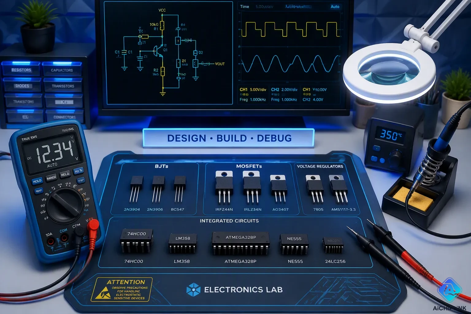
Identifying and testing different types of transistors is a key skill for anyone fixing circuits or building new electronics. Each transistor type, from BJTs to FETs and Darlington pairs, needs its own method. A proper transistor test starts with safety: technicians must turn off the circuit and check the lead assignments for base, collector, and emitter before any measurement. This article explains how transistors are grouped by material and function. It then shows basic testing with a multimeter, including the diode test and gain check. Finally, it covers advanced methods for Darlington transistors. A reliable transistor tester makes the job easier, but a multimeter works for most checks. Learning to test a transistor correctly prevents wrong guesses and wasted parts. This guide offers a clear way to test every common device.
Key Takeaways
-
Always turn off the circuit and check the datasheet for pinouts before you test any transistor.
-
Use the diode test on a multimeter to check junction health and find out if a transistor is NPN or PNP.
-
Measure the hFE gain with a multimeter's socket to check a bipolar transistor's performance.
-
Test Darlington transistors with care, since their built-in safety parts can change the readings you get.
-
For MOSFETs, check the gate threshold voltage and look for shorts instead of using the diode test.
Types of Transistors by Material and Function
Transistors use silicon or germanium as the base material. The transistor is a key part in electronics. Silicon types have a forward voltage near 0.7 V and stay stable with heat. Germanium types have a forward voltage near 0.3 V. They make a warmer sound. Germanium types react more to temperature changes. Old audio gear often uses germanium types. Each transistor has its own traits.
The main types of transistors split by job: switching, boosting, and handling power. Small-signal types handle low current. Power types manage high current. Each transistor type fits certain uses. Knowing these types of transistors helps when designing circuits.
Bipolar Junction (BJT) and Field-Effect (FET) Types
The bipolar junction transistor is a current-controlled part. A small base current controls the collector-emitter current. An npn transistor uses electrons. A pnp transistor uses holes. The part gives high current gain. Audio amps use the bjt transistor. High-frequency circuits also use the bjt transistor. The transistor works as a switch or amp. A transistor needs proper biasing to work right. An npn transistor turns on with a positive base voltage. A pnp transistor turns on with a negative base voltage. The bipolar junction transistor works well in analog circuits. An npn transistor is common in low-side switching. The npn type offers high current gain. An npn transistor works well in most designs.
The field-effect transistor (FET) is voltage-controlled. The junction field-effect transistor (JFET) uses a reverse-biased junction. The metal-oxide-semiconductor field-effect transistor (MOSFET) uses an insulated gate. The mosfet transistor offers very high input impedance. The n-channel mosfet uses electrons. The p-channel mosfet uses holes. The mosfet transistor uses less power. The n-channel mosfet shows up in digital circuits. The mosfet transistor switches faster. This part gives better heat stability. This transistor type works well in low-power designs. The mosfet works well in digital circuits. Every mosfet has a gate threshold voltage. A pnp transistor is common in high-side drive circuits. A pnp type works well for sourcing current. This part can handle high frequencies. The mosfet is ideal for power supplies. A mosfet offers high efficiency.
Specialty Types: Darlington, Phototransistor, Unijunction
Darlington types pair two bipolar parts. Total gain equals the product of the two separate gains. Two types with gain of 100 each make a combined gain of 10,000. The TIP120 has a guaranteed gain of at least 1000. This setup boosts transistor performance.
Phototransistors use light. They are more sensitive than photodiodes because of internal current boosting. A phototransistor acts as a light-sensitive switch.
Unijunction types (UJTs) have a single PN junction. They act as a switch when the emitter voltage hits a limit. This transistor type is less common today.
Basic Testing Techniques for Transistors
Safety comes first in every transistor test. A technician must power off the circuit completely before touching any component. The next step involves identifying the leads: base, collector, and emitter. These three terminals have different functions, and mixing them up ruins the measurement. A datasheet provides the correct pinout for each part number. Without this information, a simple multimeter check can produce misleading results.
Diode Test: A Prerequisite Step
The diode test serves as the foundation for all transistor testing. A bipolar junction transistor contains two PN junctions that share a common base. This internal structure matches a diode's construction exactly. That fact makes the diode-test mode the right tool for the job.
Set the multimeter to diode test mode, marked with a diode symbol on the dial. Avoid relying on resistance/ohms mode, which can give less consistent results.
A functional silicon base-emitter junction displays approximately 0.6 to 0.7 V forward voltage drop when tested in diode mode with the red probe on the base and black probe on the emitter. This reading confirms that the junction conducts properly. A short circuit shows near zero volts, while an open junction displays no reading at all. Both conditions indicate a failed part.
The diode test also reveals the transistor type. An npn transistor conducts when the red probe touches the base and the black probe touches the collector or emitter. A pnp transistor conducts in the opposite direction, with the black probe on the base. This simple check identifies the polarity without consulting a datasheet.
Electrode ID and Gain Verification
After confirming the junctions, the next step involves identifying each electrode and measuring gain. The hFE socket on a digital multimeter simplifies this process. This socket applies a fixed base current to the transistor's base and a fixed collector-emitter voltage, then measures the resulting collector current. The hFE value equals the ratio of collector current to base current, representing the DC current gain of the BJT.
A practical demonstration shows the measurement principle. The multimeter measures the collector current while the base receives a small current. The hFE value is the ratio of collector current to base current.
Pin identification requires careful attention. The TO-92 package lacks a universal standard; the lead configuration varies across manufacturers. Always verify each specific part number before testing.
For field-effect devices, the testing method differs. A technician should refer to the device's datasheet for the appropriate testing procedure, as the method is voltage-based rather than current-based. Understanding how transistors fail helps during troubleshooting. Most failures appear as shorts or opens in the junction structure. A transistor tester with dedicated sockets simplifies the process, but the simple multimeter method works for most situations. These testing methods catch faulty parts before they cause circuit damage.
Advanced Testing Techniques for Darlington Transistors
Darlington transistors are tricky to test. They use two bipolar transistors connected together. The total gain is the product of both gains. This gives very high current amplification. But the internal design adds extra parts. Many Darlingtons have built-in protection diodes and base-emitter resistors. These parts make standard testing harder. A technician must know these internal parts before testing.
Ordinary Darlington Testing
Testing a regular Darlington needs a careful plan with a multimeter. Set the meter to an appropriate resistance range. For an npn transistor, put the black lead on the base and the red lead on the collector. A pnp transistor needs the leads reversed. The forward resistance from collector to base should be within a typical range for silicon transistors. The reverse resistance should read infinite, meaning an open circuit.
The emitter-base junction needs its own check. The forward resistance here is typically higher than the collector-base value. The reverse resistance again reads infinite. Last, check collector-emitter resistance in both directions. Both readings should be near infinite. A near-zero reading means a shorted transistor. An infinite reading where forward flow should happen means an open device. This method catches most common failures.
High-Power Darlington with Protection Testing
High-power Darlingtons have extra internal parts. Protection diodes and resistors sit between the base and emitter. These parts change the expected readings during a test. The diode test mode gives the clearest view of junction health. For an npn transistor, put the positive lead on the base. Put the negative lead on the emitter. Each junction should show about 0.6–0.8 V forward drop. The base-collector junction shows a similar value.
The high gain of a Darlington does not change these diode readings. The internal cascade creates two diode drops when measuring base-emitter paths. But each junction still reads alone at 0.6–0.8 V. A short reading of 0 V means a blown junction. An open in both directions points to a lifted bond wire. A dedicated transistor tester with hFE sockets makes this easier. Many digital multimeters have these sockets for direct gain measurement. Knowing how transistors fail helps technicians read odd results. For field-effect devices, the method is different. A technician should refer to the datasheet for the appropriate testing procedure, as the method is voltage-based rather than current-based. This matters on boards with mixed components. A reliable transistor tester handles both device families well.
Transistors come in many types of transistors, each with unique traits. A proper transistor test combines a diode check with gain measurement. This method works for most devices. Always start with a diode test to verify junction health. Darlington parts need extra attention due to internal protection components. A digital multimeter handles basic checks well. A dedicated transistor tester simplifies advanced measurements. Practice these techniques regularly to build confidence. Consult datasheets for accurate pinouts before testing. Every test reveals useful information about component health. How to test a transistor becomes clearer with each attempt. Reliable testing prevents wasted parts and circuit damage. Start testing your transistors today to build confidence and troubleshoot circuits with ease.

Written by Jack Elliott from AIChipLink.
AIChipLink, one of the fastest-growing global independent electronic components distributors in the world, offers millions of products from thousands of manufacturers, and many of our in-stock parts is available to ship same day.
We mainly source and distribute integrated circuit (IC) products of brands such as Broadcom, Microchip, Texas Instruments, Infineon, NXP, Analog Devices, Qualcomm, Intel, etc., which are widely used in communication & network, telecom, industrial control, new energy and automotive electronics.
Empowered by AI, Linked to the Future. Get started on AIChipLink and submit your RFQ online today!
Frequently Asked Questions
What is the safest way to begin a transistor test?
Before touching any part, a technician must turn off the circuit completely. Next, look up the correct pinout in the datasheet. The diode test mode on a multimeter gives the first reading. This method keeps both the transistor and the meter safe from damage.
How does a multimeter identify an npn transistor versus a pnp transistor?
The diode test shows the polarity. For an npn transistor, current flows when the red probe is on the base and the black probe is on the collector or emitter. A pnp transistor conducts the opposite way. This easy check works even without a datasheet.
Why do Darlington transistors require special testing procedures?
Darlington parts have two bipolar transistors plus built-in protection diodes and base-emitter resistors. These extra parts change the expected resistance readings. A technician must consider these internal parts during testing. The diode test mode offers the clearest view of junction health for these devices.
Can a multimeter test a mosfet transistor?
Yes, but the method is different from BJT testing. A technician should refer to the device's datasheet for the appropriate testing procedure, as the method is voltage-based rather than current-based.
What does the hFE socket measure on a transistor tester?
The hFE socket sends a fixed base current to the transistor's base and applies a fixed collector-emitter voltage, then measures the resulting collector current. The hFE value is the ratio of collector current to base current.