What is a Unijunction Transistor and How Does It Work
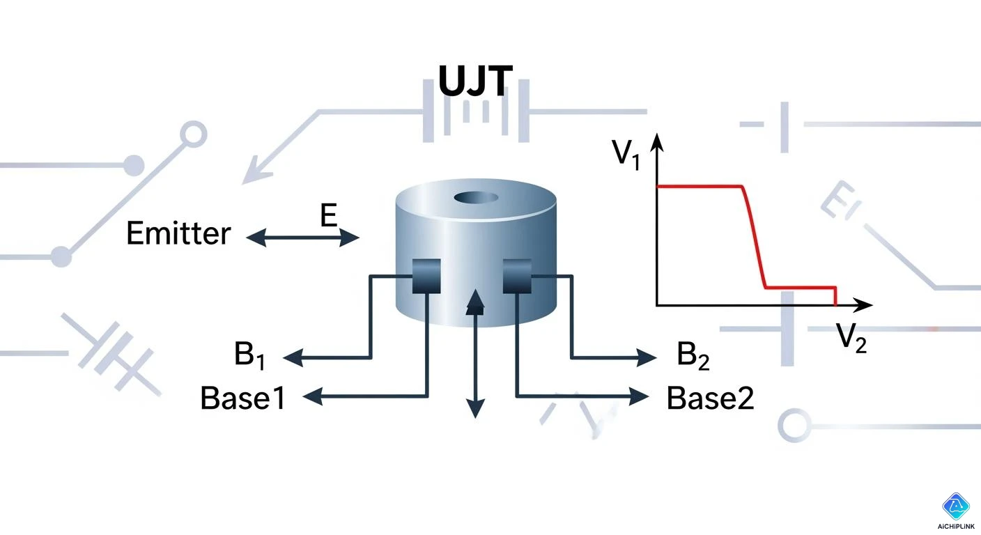
You can see the unijunction transistor in lots of devices. This part works as a basic electronic switch. It is special because it has three wires and one junction. People use a ujt to control circuits. It is helpful when you need an oscillator or a simple switch. Its special shape lets it turn things 'ON' or 'OFF'. This makes it useful for timing and triggering jobs.
| Definition | Function |
|---|---|
| A basic electronic switch | Used in things like oscillators and triggering devices |
Key Takeaways
-
A unijunction transistor (UJT) is a simple electronic switch. It has three terminals and one junction. This makes it easy to use in circuits.
-
The UJT is good for making oscillators and timing circuits. It can turn on and off very fast. This helps control when devices work.
-
The UJT has a special negative resistance property. This lets it make repeating signals. These signals are helpful in many electronic uses.
-
You can find the UJT's pins easily. Base 1 (B1) and Base 2 (B2) are at the ends of the n-type bar. The Emitter (E) is close to Base 2.
-
To make a UJT oscillator, you can change resistor and capacitor values. This changes the frequency. It makes the UJT a useful tool for engineers and hobbyists.
Unijunction Transistor Basics
What is a UJT?
A unijunction transistor is a special kind of semiconductor part. It has three wires. These are called B1, B2, and E. This makes the ujt different from other transistors. For example, a bipolar junction transistor has two junctions. It can make signals stronger. The unijunction transistor only has one junction. It cannot make signals stronger. People use it as a switch in circuits.
When you put voltage on the ujt, something happens inside. A potential gradient forms in the n-type silicon bar. The emitter is close to one end of this bar. If you turn up the voltage at the emitter, the current stays low at first. When the emitter voltage gets high enough, the current jumps up fast. This makes the resistance between the emitter and base drop quickly. The ujt starts to let current flow. You can use this to control other parts of your circuit.
Key Features of UJT
The ujt is special because of its features. Here are some things you should know:
-
The ujt has one PN junction and three terminals. This makes it simple to use in easy circuits.
-
It has a property called negative resistance. When the emitter voltage gets high enough, more current flows. But the voltage across the device drops. Most electronic parts do not do this.
-
People use the ujt to make pulse signals. These signals help build timer circuits or oscillators that repeat patterns.
-
The ujt is good for turning things on and off fast. You can find it in flip-flop circuits and other switching jobs.
-
The ujt has a heavily doped P-type emitter and a lightly doped N-type base. This means current can only go one way through the device.
Tip: If you want to make an easy oscillator or timer, the ujt is a good pick. It switches well and is simple to understand.
You will see the unijunction transistor in many electronics projects. It can make pulses and switch fast. This makes it popular with engineers and hobbyists.
UJT Construction and Symbol
Physical Structure and Leads
You can find the unijunction transistor built with simple materials. The main part is an n-type silicon bar. This bar acts as the backbone of the device. Engineers place electrical contacts at both ends of the bar. These contacts are called Base 1 (B1) and Base 2 (B2). Near one end, you see a heavily doped p-type emitter. This emitter forms a pn-junction close to Base 2. The junction is the heart of the UJT. When you leave the emitter terminal open, the resistance between B1 and B2 stays high. This design lets the UJT act as a switch in many circuits.
You can spot the three leads easily:
-
B1 (Base 1): One end of the n-type bar.
-
B2 (Base 2): The other end of the n-type bar.
-
E (Emitter): The p-type region near B2.
The emitter sits close to B2, not in the middle. This placement helps the UJT work as a trigger device. You can use these leads to connect the UJT in different ways. Each lead has a special job in the circuit.
Note: The n-type bar gives the UJT its high resistance. The p-type emitter creates the junction that makes switching possible.
Circuit Symbol and Pinout
You can recognize the UJT symbol in circuit diagrams. The symbol shows one junction with two bases and an emitter. You see a straight line for the n-type bar. The bases sit at each end. The emitter connects to the bar near B2 with an arrow pointing inward.
The UJT symbol features one junction with two bases and an emitter. It is commonly used in oscillator circuits.
Here is a simple table to help you identify the pins:
| Pin Name | Symbol Label | Function |
|---|---|---|
| B1 | Base 1 | Lower end of n-type bar |
| B2 | Base 2 | Upper end of n-type bar |
| E | Emitter | Junction near B2 |
You can use this table when wiring the UJT in your project. The emitter always sits closer to B2. This helps you place the UJT correctly in your circuit.
UJT Working Principle
Emitter Open Condition
If you leave the emitter open, the unijunction transistor does not let current flow between the emitter and base 1. No current moves from base 1 to the emitter. Only a tiny current can go from base 1 to base 2. The ujt stays off in this state. The device will not turn on until the emitter voltage gets high enough. This level is important because it decides when the ujt will start working in your circuit. Many circuits use this to control timing. If you want your circuit to have good timing, you need to know how the emitter open condition works.
Note: The emitter features of ujt in this state help you make timing circuits that wait for a certain voltage before switching.
Emitter Forward Bias Operation
When you make the emitter voltage higher, you start to forward bias the junction. This changes how the ujt acts. Here is what happens step by step:
-
Forward biasing the emitter makes the voltage between the emitter and base go up.
-
As the voltage rises, the emitter current goes up slowly at first.
-
When the voltage hits a special value called the "peak point," the emitter current jumps up fast.
-
At this peak point, charge carriers move into the channel inside the unijunction transistor.
-
The channel resistance drops, and the device switches to a low-resistance state.
-
The ujt now lets a lot of current flow from the emitter to base 1.
You can see that the ujt works like a switch. It stays off until the emitter voltage is high enough. Then it turns on very quickly. This switching is why the ujt is used in many oscillator and timing circuits.
Negative Resistance Region
After the ujt turns on, it goes into a special part of its work called the negative resistance region. In this region, something strange happens. If you keep making the emitter current higher, the voltage across the device drops. Most electronic parts do not do this. This feature makes the unijunction transistor great for oscillator circuits.
The negative resistance region helps you make oscillators that create repeating signals. When you use a ujt in an oscillator, the negative resistance cancels out the positive resistance in the rest of the circuit. This balance lets the circuit make steady oscillations without extra feedback loops. The ujt helps a capacitor charge and discharge fast, which makes sharp pulses. These pulses are important for timing and control in many electronic devices.
Tip: If you want to make a simple oscillator, the negative resistance region of the ujt is the main feature that makes it work.
You can see how the unijunction transistor switches between high and low resistance. This switching, along with the negative resistance region, gives you strong control over timing and pulse making in your circuits.
UJT Characteristics and Applications
Main Characteristics
The ujt has special electrical features. It is different from other transistors because it has only one pn junction. This gives it a negative resistance property. When you trigger the emitter, the current goes up fast, but the voltage goes down. Most electronic parts do not act this way. The ujt does not work as a linear amplifier. People use it as a switch or in oscillator circuits.
Here is a table that shows how the ujt compares to a bipolar junction transistor:
| Characteristic | UJT | BJT |
|---|---|---|
| Junction Type | Single pn junction | Multiple pn junctions |
| Main Function | Electrically controlled switch | Amplifier and switch |
| Oscillation Capability | Used in oscillators and pulse circuits | Not mainly for oscillators |
| Resistance Behavior | Shows negative resistance | No negative resistance |
| Emitter Current | Increases fast after triggering | Controlled by base current |
Most ujt models, like the 2N2646, can handle up to 30 volts and 50 mA. Some models can go up to 40 volts. The device has a low peak point current. It can work in many different temperatures.
Tip: The negative resistance region makes the ujt great for timing and pulse circuits.
Common Applications
You can find the ujt in many timing and control circuits. Here are some common uses:
-
Oscillator circuits make repeating signals.
-
Pulse generators create sharp, timed pulses.
-
SCR trigger circuits help control power.
-
Timing circuits are used in alarms and timers.
-
Simple lamp dimmers for homes.
-
Basic power control jobs.
The ujt works well in switching pulse generator circuits. You can use it to make ujt relaxation oscillators. These create sharp pulses by charging and discharging a capacitor.
The ujt’s negative resistance helps you build simple and reliable oscillator circuits.
Simple Example Calculation
Let’s see how you use a ujt in an oscillator. Suppose you want an oscillator to run at 1 kHz. You have a 100 nF capacitor. You can use this formula:
f = 1 / (0.82 × C × R)
You know f = 1,000 Hz and C = 100 nF (which is 0.1 × 10^-6 F). To find R:
-
Change the formula:
R = 1 / (0.82 × C × f) -
Put in the numbers:
R = 1 / (0.82 × 0.1 × 10^-6 × 1,000) -
Do the math:
R = 1 / (0.082 × 10^-3) -
Final answer:
R ≈ 12.19 kΩ
So, you need a resistor of about 12 kΩ for your oscillator circuit.
Note: You can change the frequency by changing the resistor or capacitor values.
You now know a ujt has one pn-junction and three terminals. This setup makes it easy to control timing and switching. The resistance between the bases is called inter-base resistance. It helps decide how the device works. Many engineers like the ujt because it is reliable and simple to use. If you want to learn more, you can check out programmable unijunction transistors. You can also try making a relaxation oscillator. These projects show how timing and switching work in real circuits.

Written by Jack Elliott from AIChipLink.
AIChipLink, one of the fastest-growing global independent electronic components distributors in the world, offers millions of products from thousands of manufacturers, and many of our in-stock parts is available to ship same day.
We mainly source and distribute integrated circuit (IC) products of brands such as Broadcom, Microchip, Texas Instruments, Infineon, NXP, Analog Devices, Qualcomm, Intel, etc., which are widely used in communication & network, telecom, industrial control, new energy and automotive electronics.
Empowered by AI, Linked to the Future. Get started on AIChipLink and submit your RFQ online today!
Frequently Asked Questions
What is the main use of a unijunction transistor?
You use a unijunction transistor to make timing circuits and oscillators. It helps you create pulses and control when things turn on or off in electronic devices.
How do you identify the pins on a UJT?
You can check the datasheet or look for markings. Usually, B1 and B2 sit at the ends of the bar, and the emitter sits near B2. Tip: The emitter pin often has a dot or special mark.
Why does a UJT show negative resistance?
When you increase the emitter voltage past a certain point, the current rises fast, but the voltage drops. This creates negative resistance. You can use this feature to build oscillators.
Can you use a UJT to amplify signals?
No, you cannot use a UJT to amplify signals. You use it as a switch or pulse generator.