A Comprehensive Guide to Optical Encoder Types and Applications
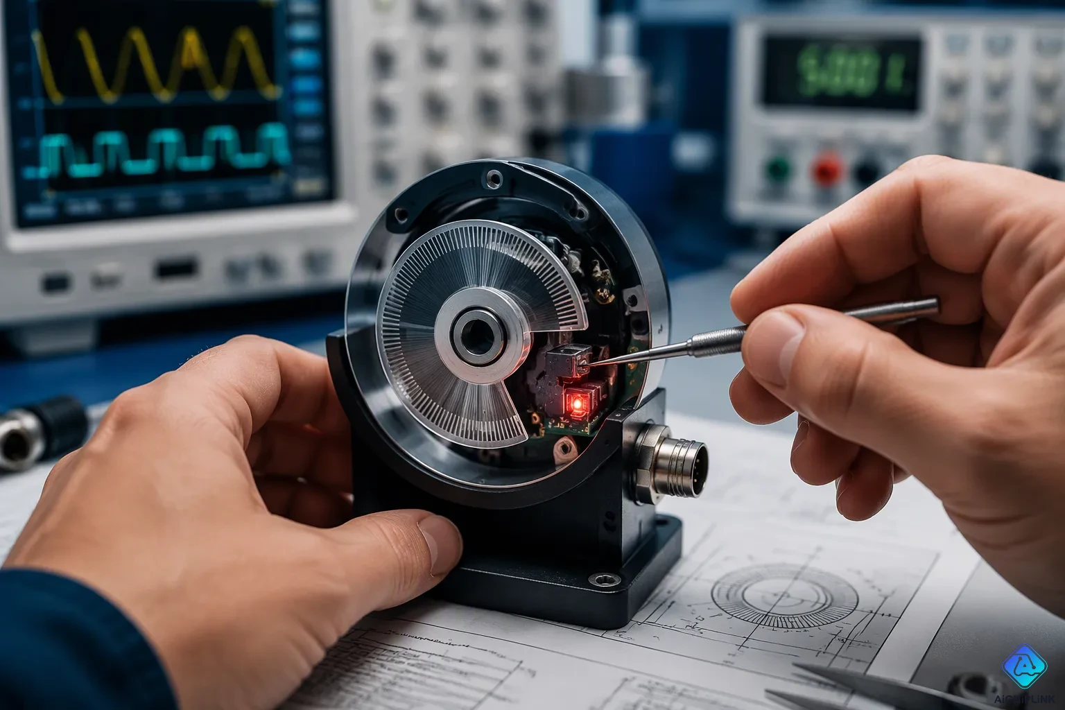
An optical encoder is a sensor that turns physical motion into electrical signals. You should care because those signals give a controller precise position and speed feedback. That feedback keeps motors, robots, and machines accurate.
Choosing the right setup is confusing. Many encoder types and specs exist, and the electronics that read them often need careful power sequencing across multiple voltage rails. A Power Sequencer IC helps manage that startup order. This guide helps you compare encoder types, weigh key specifications, and plan a safe power-up order for the electronics that read them. A practical checklist at the end ties everything together.
Key Takeaways
-
Incremental encoders count pulses to track motion from one point to another. Absolute encoders give the exact position as soon as the power comes on.
-
Check resolution, accuracy, and repeatability before you pick an encoder. Higher resolution does not fix mechanical errors.
-
Make sure the encoder's output format matches your controller. HTL works with PLCs. TTL is good for high-speed, long-distance runs.
-
Use a power sequencer IC to turn on the voltage rails in the right order. This prevents damage and helps the system start up reliably.
-
Choose an encoder that fits your job. Absolute encoders remember their position after the power goes out. Incremental encoders are a good choice for controlling speed.
How Optical Encoders Work
Core Components and Light Path
Every optical encoder depends on three main parts: a light source, a sensor, and a code disk that rotates or moves in a straight line. The light source shines through the disk onto the sensor. The sensor reads the pattern of light and dark areas and turns it into an electrical signal. That signal carries exact motion information, like speed.
Masked encoders add a fixed mask to the setup. The disk has a series of tracks, and the mask holds a matching track for each one, drilled with small holes called windows. As the disk turns, the windows open and close in different patterns. Each arc of rotation makes a distinct pattern, and the sensor behind the mask identifies it. Each sensor then stands for one signal.
The physical layout changes by type. In a transmission encoder, a code wheel with fine slits sits between a light emitter and a photosensor. The wheel turns and lets light through or blocks it, making an on/off signal for detecting rotation angle. In a reflection encoder, the emitter and photosensor sit on the same side of the wheel, and the angle comes from reflected versus non-reflected light. High accuracy needs a steady emitter, such as an LED, plus a fast photosensor that can catch complex slit patterns reliably.
Light Pulses to Output Signals
Turning light into a usable signal follows a clear chain. An infrared LED sends a beam toward the coded disk. The turning disk, patterned with clear and opaque sections, blocks and passes that light in turn. A photosensor assembly of photodetectors or phototransistors then detects the resulting changes.
The photodetectors turn the received light into an electrical signal, making a sinusoidal or square wave. The pulse train (light on, no light off) travels through the electronics board to a controller, counter, or PLC for motion feedback. Silicon photodiodes handle this step directly with high sensitivity and fast response. Phototransistors boost the photocurrent when you need a larger output signal. A quadrature detection array uses four light-sensing elements spaced 90° apart in a differential setup to maximize noise immunity. Signal conditioning with trans-impedance amplifiers keeps the signal intact across varying light intensities.
Incremental vs. Absolute Encoders
The two families answer different questions. An incremental encoder tells you how far the shaft has moved since you started counting. An absolute encoder tells you exactly where the shaft is at any moment, with no counting required.
Incremental Encoders and Outputs
An incremental encoder reports motion as a stream of pulses. Each pulse marks a small step of rotation, and your controller counts the pulses to track speed and relative position. This design is simple, fast, and well suited to motor feedback.
The output format matters as much as the resolution. HTL push-pull outputs use two transistors in a totem configuration, so the signal is always firmly high or low, and the output voltage equals the supply voltage when active. You choose HTL when your PLC or variable frequency drive expects 12V or 24V levels. TTL (RS422) outputs carry differential signals, which excel at high-speed operation and long-distance transmission, so they fit applications needing precise positioning and fast response. Open collector NPN outputs sink current and suit short cable runs, though they are typically more susceptible to electrical noise. Some models offer programmable outputs, so one encoder can serve several applications and you carry fewer spare parts.
| Output Signal Format | Signal Characteristics | Typical Applications |
|---|---|---|
| HTL (Push-Pull) | Robust, straightforward signal transmission; compatible with a wide range of control systems | PLCs and variable frequency drives (VFDs) |
| TTL (RS422) | Differential signals; excellent for high-speed operation and long-distance transmission | Applications requiring precise positioning and fast response times |
One limitation deserves attention. After a power loss, an incremental encoder cannot relay usable information until the shaft has made at least one full turn. Counting restarts from zero, and you must re-establish a reference point. A Z index pulse marks the shaft position once per 360-degree rotation, which gives you a location reference when this limitation is unacceptable.
Absolute Encoders: Single- and Multi-Turn
An absolute encoder encodes each shaft position as a unique pattern on the disc. On power-up, it immediately reports its true position, even if the shaft rotated while unpowered. No homing move is needed, and position is retained and known at all times.
Single-turn versions resolve position within one revolution. Multi-turn versions add a revolution count, so they track position across many turns. Resolution ranges vary widely by model. The AD36 hollow-shaft encoder reaches up to 22 bit single-turn and up to 12 bit multi-turn. The AI25 SSI encoder matches that 22-bit single-turn ceiling with up to 12 bit multi-turn. The AR62/63 magnetic rotary encoder offers 12 bit single-turn and 12–16 bit multi-turn. The C-series models span 15–17 bit, with the C1040 at 17–19 bit and the C1752 at 18–20 bit.
Pick absolute encoders when position must survive a power cycle. CNC axes, robotic joints, and steering systems all benefit from instant, trustworthy position data at startup.
Key Specifications to Evaluate
Resolution, Accuracy, and Repeatability
These three terms sound similar, but they measure different things. Resolution is the smallest step the encoder can report. Accuracy is how close the reported position is to the true position. Repeatability is how steadily the encoder returns to the same commanded position. A system can repeat well and still be inaccurate, or the other way around.
| Concept | What It Means | Typical Values |
|---|---|---|
| Resolution | Smallest measurable step | Up to 10,000 PPR directly, 40,000 PPR via interpolation |
| Accuracy | Gap between target and actual position | About 0.18° typical for absolute optical shaft encoders |
| Repeatability | Consistency of returning to a position | Often 2–10 times better than accuracy |
Higher resolution does not fix accuracy errors that come from the whole system. Mechanical problems like gearing backlash, hysteresis, or a loose belt can lower repeatability no matter how fine the code disk is. Check all three numbers before you decide.
Environmental and Interface Factors
Where you mount the encoder sets the environmental bar. Indoor encoders commonly carry IP54 or IP65 ratings and run from -10°C to +70°C. Outdoor units typically reach IP67 or IP68 and handle -40°C to +85°C. Demanding sites near ovens or in cold storage often need -40°C to +100°C. IP ratings follow IEC 60529, and temperature cycling tests follow IEC 60068-2-14.
The interface must match your controller. HTL push-pull outputs mirror the input voltage, so 24 V in gives 24 V out, which suits PLCs and drives. TTL uses RS-422 signaling with a locked 5 V output and tolerates noisy environments, though it needs at least about 4.5 V input. RS-422 carries differential signals for noise-resistant short runs. SSI sends synchronous absolute position data with a clock, and BiSS C adds bidirectional configuration over an open protocol. BiSS Line trims this to two wires for tight spaces.
Power Sequencing for Encoder Systems
Power sequencing means turning several voltage rails on and off in a set order. A board with many rails can act up when all of them rise at the same time. A power sequencer IC forces a planned order, so each rail settles before the next one starts. The device also sets wait times between enables and controls the shutdown order. This controlled power-up protects sensitive parts and makes the startup sequence the same every time.
Power Sequencer ICs and Startup Sequence
A dedicated power sequencer IC checks one rail, then turns on the next. The ADM1166 Super Sequencer shows this pattern in a system that has an encoder. It makes sure a rail is in range, then drives an enable pin high for the next rail. In one state it checks the 1.0V rail, then sets 1.8V_EN high. In the next state it confirms 1.8V and turns on the 1.35V rail. A power-good signal, from the supply or a monitor, shows a steady voltage and can turn on another supply.
You can build this in several ways. Power sequencing ICs, an integrated PMIC, or discrete circuits made from DC-DC ICs, Power Good circuits, discharge circuits, and diodes all work. Programmable delay power sequencer ICs and multi-rail power switch ICs add flexibility for complex power sequencing. Parts like the LTC2924 and LM3880-Q1 show what this category looks like. Power management ICs and power monitoring and sequencing blocks often include this power sequencing function.
Managing Two or More Internal Voltage Domains
Encoder readout electronics and controllers often run on two or more internal voltage domains. Each domain needs its own supply, and the order matters. A well-controlled startup sequence protects signal integrity. A wrong order can cause latch-up or bus contention on shared lines.
Plan both directions. Startup and shutdown power sequencing deserve equal attention, because shutdown sequencing stops back-feeding between power supplies. Compare your whole system startup sequence with the recommended startup sequence in each datasheet. Check that power regulators and system power supplies follow the same order. A small power sequencer circuit at the front end gives you that control across multiple power rails.
Matching Encoder Types to Applications
Industrial and Robotics Use Cases
Incremental encoders work best when speed or relative change matters more than exact position. You will find them in robotics, CNC machines, conveyor systems, motor feedback with variable frequency drives, and automated positioning systems. The table below shows what each area uses them for.
| Application Domain | Role of Incremental Encoder |
|---|---|
| Robotics | Measuring joint position and movement |
| Industrial automation | Conveyors and assembly lines |
| CNC machinery | Precision position and speed control |
| Elevators and escalators | Motion and speed control for safe operation |
| Renewable energy | Blade angle measurement in wind turbines |
A conveyor shows the pattern clearly. A photoelectric sensor spots a product entering, and the PLC records the encoder pulse count, say 5232 pulses. At the exit sensor, the count reads again, perhaps 6311 pulses. The difference of 1079 counts tells the system how far the product traveled. The encoder never knows the product's exact physical location, only the amount of movement. That makes it great for conveyor tracking, speed measurement, and motion control.
Absolute encoders take over when position must survive a power cycle. CNC axes need instant, trustworthy coordinates at startup, and robotic joints benefit from the same certainty. A homing move wastes time on every restart.
Consumer, Medical, and Automotive Applications
Absolute encoders dominate applications where a wrong position reading is costly. Automotive holds roughly 25% of the market, driven by EV motors and ADAS systems. Aerospace accounts for about 15%, serving high-precision navigation and avionics control. Medical robotics is the fastest-growing segment: more than 35% of new medical robotic systems in 2024 integrated miniature absolute encoders, with growth near 21% that year. Minimally invasive surgical devices and wearable robotic aids rely on them. Consumer electronics and specialty industrial uses make up the remaining ~12%, covering compact motion-controlled devices like smart thermostats that adjust settings to user preferences and environmental conditions.
Medical infusion pumps and automotive steering angle sensing sit at the strict end of power sequencing requirements. These systems run sensitive readout electronics across multiple power rails, and a sloppy startup sequence can corrupt position data or trigger latch-up. A power sequencer ic enforces the correct order, holding each rail until the prior one settles. Designers of such devices also watch form factors: encoder models under 5 mm thick rose 45% in 2024 versus 2023, enabling wearables and micro-automation.
Wherever strict power sequencing applies, verify that your power supplies and power regulators follow the datasheet order. Check the shutdown direction too, since reverse-order shutdown can back-feed between rails.
Incremental encoders count pulses for relative motion. Absolute encoders report true position at power-up, after unpowered movement. Your choice depends on whether position must survive a power cycle.
Specifications narrow the field: resolution, accuracy, repeatability, IP rating, and interface. Power sequencing matters too. A power sequencer ic enforces rail order, and a power sequencing ic guards readout electronics from latch-up. Check the startup sequence against each datasheet.
Use this checklist:
-
Match encoder type to position-retention needs.
-
Confirm resolution, accuracy, and repeatability targets.
-
Verify IP rating and temperature range.
-
Match the interface to your controller.
-
Validate rail order at power-up and shutdown.
Absolute encoders will keep displacing incremental types. Serial formats like BiSS, SSI, and EnDat will carry finer position data.

Written by Jack Elliott from AIChipLink.
AIChipLink, one of the fastest-growing global independent electronic components distributors in the world, offers millions of products from thousands of manufacturers, and many of our in-stock parts is available to ship same day.
We mainly source and distribute integrated circuit (IC) products of brands such as Broadcom, Microchip, Texas Instruments, Infineon, NXP, Analog Devices, Qualcomm, Intel, etc., which are widely used in communication & network, telecom, industrial control, new energy and automotive electronics.
Empowered by AI, Linked to the Future. Get started on AIChipLink and submit your RFQ online today!
Frequently Asked Questions
How do I choose between an incremental and an absolute encoder?
Ask one question first: must position survive a power cycle? If yes, pick an absolute encoder. It reports true position at startup with no homing move. If you only need speed or relative movement, an incremental encoder costs less and works well.
Does higher resolution always mean better accuracy?
No. Resolution is the smallest step the encoder reports. Accuracy is how close that report sits to the true position. Mechanical problems like backlash or a loose belt can hurt accuracy no matter how fine the disk is. Check all three numbers: resolution, accuracy, and repeatability.
Which output format should I match to my controller?
Match the format to what your controller expects. HTL push-pull suits PLCs and variable frequency drives at 12V or 24V levels. TTL (RS-422) carries differential signals for high-speed work and long cable runs. Open collector NPN fits short runs in quiet electrical environments.
Why does power sequencing matter for encoder electronics?
Readout electronics often run on two or more voltage domains. A wrong startup order can cause latch-up or bus contention on shared lines. A power sequencer IC turns each rail on in a set order and holds it until the prior rail settles. Check shutdown order too.
What IP rating do I need for my mounting location?
Match the rating to the site. Indoor mounts commonly use IP54 or IP65 and run from -10°C to +70°C. Outdoor units typically reach IP67 or IP68 and handle -40°C to +85°C. Sites near ovens or in cold storage often need -40°C to +100°C.