What Is a Rotary Variable Differential Transformer (RVDT)?
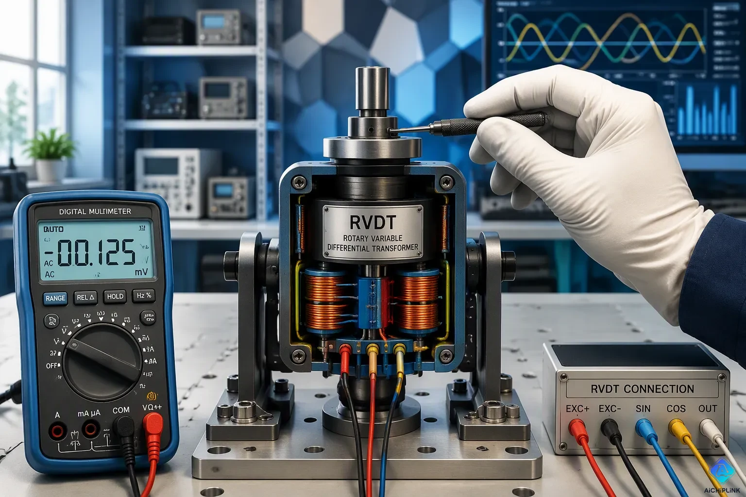
A rotary variable differential transformer is an electromechanical transducer that measures angular displacement. It gives a variable AC output voltage that matches the angular displacement of its rotor shaft. The RVDT works on the same principle as the linear variable differential transformer. But engineers design it for rotary motion instead of linear displacement. This device plays a key role in measuring exact angular positions across many industries. Its contactless design and dependable performance make the RVDT a top choice for measuring absolute rotary angle. The transformer-based structure allows for accurate and repeatable measurements in tough environments.
Key Takeaways
-
An RVDT measures how far a shaft turns. It gives an AC voltage that matches the angle.
-
The RVDT has no touching parts. This design gives long life and high accuracy.
-
The RVDT works best within a limited angle range. Most designs cover up to about ±40 degrees.
-
You can find RVDTs in airplanes, robots, and valve systems. They provide precise angle feedback.
-
The RVDT needs AC power. Temperature changes can affect its accuracy.
RVDT Construction and Transformer Design
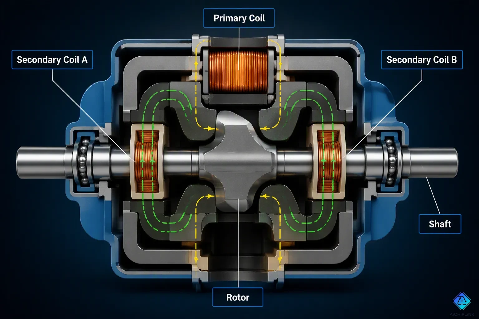
A rotary variable differential transformer works like an electrical transformer. It has one primary coil and two secondary coils. This transformer-based sensor turns mechanical rotation into an electrical signal. The primary coil gets an AC excitation voltage. The two secondary coils sit on opposite sides of the primary coil. The core goes through the center of the coil assembly. The RVDT construction allows contactless angular measurement.
The cam-shaped ferromagnetic element connects to a rotating shaft. An outside force turns the shaft. This element changes the electromagnetic coupling between the primary coil and the secondary windings. This change causes different voltages in each secondary winding. The sensor measures the difference between these voltages. The differential output matches the angular displacement of the shaft. This design removes mechanical wear completely. The parts do not touch during normal operation.
The two secondary windings are called secondary coil A and secondary coil B. At the center null position, both windings make equal voltages. The voltage difference becomes zero. As the shaft turns, secondary coil A has stronger coupling. Secondary coil B has weaker coupling. The voltage difference grows linearly with rotation angle. The device gives essentially infinite resolution. The resolution is limited only by the signal conditioner electronics. The accuracy specification reaches better than ±0.5% of Full Scale within ±45 degrees of rotation. This high accuracy makes the device good for precision measurement tasks.
Core Windings and Rotor
The primary windings and secondary windings make up the stationary assembly. The rotor is the moving element. Magnetic coupling between these parts changes with core position. The cam-shaped element decides how the magnetic field spreads across the secondary windings. The ferromagnetic material boosts the field in certain areas. This boost creates the differential output voltage. Engineers wind the coils on a bobbin to keep magnetic performance consistent.
Design for Rotary Motion
An LVDT measures linear displacement. An RVDT measures rotary motion instead. Adapting for rotation requires a different core shape. The transformer must allow radial changes in magnetic coupling. The stationary windings keep a similar arrangement to an LVDT. The operation of the RVDT stays strong in harsh environments. The accuracy reaches better than ±0.5% of Full Scale within ±45 degrees of rotation. The contactless design ensures long service life in demanding industrial settings. This design also cuts the need for maintenance over time.
RVDT Working Principle
The rotary variable differential transformer senses rotation by changing how its coils are electromagnetically coupled. A primary winding gets an AC excitation voltage. Two secondary windings pick up caused voltages. The rotor position controls how much flux reaches each secondary coil. This section explains the three main positions and how the output voltage relates to the rotor shaft angular displacement.
Three Core Positions
The RVDT works in three different zones. Each zone gives a unique output signature. The table below sums up how the device behaves at each position.
| Displacement Position | Core/Shaft Condition | Secondary Coil Behavior | Output Voltage (Eo = ES1 − ES2) | Phase Relationship |
|---|---|---|---|---|
| Null | Primary and core with secondary winding are placed in a balanced way | Equal EMF caused in both secondary coils (ES1 = ES2) | 0 V | Not applicable (no differential output) |
| Positive (anticlockwise rotation) | Core turns anticlockwise | ES1 increases | Positive | In phase with primary voltage |
| Negative (clockwise rotation) | Core turns clockwise | ES2 increases | Negative | Out of phase with primary voltage |
At the null position, the rotor sits in a balanced spot between the two secondary coils. Both secondary coils make equal voltages. The difference between them equals zero. No output voltage shows up at this point.
When the shaft turns anticlockwise, the rotor moves toward one secondary coil. That coil picks up stronger electromagnetic coupling. Its caused voltage rises. The other secondary coil loses coupling. Its voltage drops. The differential output becomes positive. This output stays in phase with the primary voltage.
When the shaft turns clockwise, the opposite takes place. The second secondary coil gains stronger coupling. Its voltage rises above the first. The differential output becomes negative. This output is out of phase with the primary voltage. The operation is fully reversible and symmetric.
Output Voltage and Angular Displacement
The output voltage versus shaft angular displacement follows a straight-line relationship within the measurement range. The differential output voltage equals two times the gain times the rotor angle. In simple terms, the output grows steadily as the shaft turns further from null. The secondary voltage equals the null voltage plus or minus the gain times the angle. The sum of the two secondary voltages stays constant throughout the range.
The rotor angle relates to the secondary voltages through a normalized difference. The angle equals the gain times the difference of the two secondary voltages divided by their sum. This relationship holds because the sum remains fixed. The device makes a proportional electrical signal that directly tracks the shaft angular displacement.
The linearity range usually spans plus or minus 40 degrees from null. Some designs extend to about plus or minus 60 degrees or less. Sensitivity ranges from about 2 to 5 millivolts per degree of rotation. The phase and amplitude of the output carry the position information. The RVDT measures absolute rotary angle, not just a change from a previous reading. This absolute rotary angle capability means the device reports the true shaft position at power-up without homing. The transformer principle makes sure the output stays tied to the physical rotor position at all times.
RVDT Advantages and Limitations
Key Advantages
A rotary variable differential transformer has several strengths that make it different from older sensing tools. Its non-contact inductive magnetic coupling removes sliding contacts entirely. This design gives the device almost unlimited resolution and a long life. A potentiometer wears out over time because its wiper rubs against a resistive track. An RVDT has no part that wears out. No physical contact means the sensor gives high resolution and repeatability even after decades of use.
The RVDT also works well in harsh conditions. It resists temperature, humidity, and electromagnetic interference when properly shielded. The AC version can handle temperatures up to 150 °C without compensation circuits. Its fail-safe output is another benefit. The center position gives almost zero output. An open coil creates a clear fault. These features make the device reliable for important measurement tasks.
| Feature | RVDT Specification |
|---|---|
| Operating principle | Non-contact inductive magnetic coupling |
| Resolution | Virtually infinite |
| Mechanical design | Precision ball bearings |
| Angular range (AC) | ±15° to ±60° |
| Angular range (DC) | Up to ±75° |
| Temperature range | Up to 150 °C (AC) |
| Key advantage over potentiometers | No sliding contacts → long cycle life |
Notable Limitations
The RVDT has a limited turning range. Its linear range covers any range up to ±70° at most. This limit greatly affects which sensor you pick. Engineers pick this device when they need to measure within that narrow window. Uses beyond this range need a different sensing method.
The device also needs AC power for the primary winding. This need makes the signal conditioning circuit more complex. Temperature changes affect accuracy too. The transformer idea depends on stable magnetic properties. Big temperature swings can change the output. These limits do not reduce the device's value. They just define the range where it works best.
RVDT Applications in Rotary and Absolute Positioning
Engineers pick this device for important measuring jobs in many fields. The no-contact design and reliable signal make it a top pick for long use. This sensor handles jobs needing absolute rotary angle feedback where dependability is key.
Aerospace and Flight Control
Aerospace systems need high reliability in tough conditions. The RVDT works steadily and reliably in these environments. Flight control systems use these devices to check high-lift surfaces and their angle. Missile fin control depends on the device for exact angular feedback. The device sends live data to guidance computer for exact moves. Precision servo controls in aircraft also use this tech for accurate motion.
Aircraft engines also commonly rely on this device. It measures the valve motion in fuel control systems accurately. An aviation fuel conditioning system uses it to control fuel flow accurately. The output ensures the system knows the valve state instantly at startup. Landing gears and cockpit controls also benefit from rugged construction and long service life. The harsh conditions inside an engine bay do not affect performance. Missile seekers and precision avionics use this device for reliable measurement.
Industrial and Valve Position Sensing
Industrial jobs need reliable feedback over long periods without upkeep. Manufacturing machines use this device for exact control in automated jobs. Robotics systems rely on the RVDT for feedback on joint orientation and gripper state. The high accuracy within a limited rotation range fits these tasks well. Automated assembly lines depend on this component for consistent operation.
Valve position sensing is a major use case for this technology. Quarter-turn valves need exact monitoring of their open or closed state. This device gives feedback without contact wear. Actuator feedback systems use it to confirm that the valves have reached their commanded position. Power generation uses it to monitor turbine blade and generator rotor state for best efficiency. Medical gear like CT scanners and X-ray machines also depend on this device for precise operation. Surgical robots use this part for accurate tool placement. The oil and gas industry gains from high reliability in harsh places where other methods fail.
A rotary variable differential transformer is an electromechanical transducer that measures angular displacement through a variable AC output voltage. Its construction uses a primary winding, two secondary windings, and a cam-shaped rotor. The working principle relies on differential magnetic coupling across null, positive, and negative positions. The device balances high accuracy and infinite resolution against a limited angular range and AC excitation needs. Industries depend on the RVDT for precise rotary and absolute positioning in flight control, valve sensing, and robotics. Growing demand in autonomous vehicles, renewable energy, and digital control systems keeps this sensor relevant in modern engineering.

Written by Jack Elliott from AIChipLink.
AIChipLink, one of the fastest-growing global independent electronic components distributors in the world, offers millions of products from thousands of manufacturers, and many of our in-stock parts is available to ship same day.
We mainly source and distribute integrated circuit (IC) products of brands such as Broadcom, Microchip, Texas Instruments, Infineon, NXP, Analog Devices, Qualcomm, Intel, etc., which are widely used in communication & network, telecom, industrial control, new energy and automotive electronics.
Empowered by AI, Linked to the Future. Get started on AIChipLink and submit your RFQ online today!
Frequently Asked Questions
What does an RVDT actually measure?
An RVDT measures how far a shaft turns. It sends out an AC voltage that matches the rotor angle. The device reports the exact rotary angle. When you turn it on, it knows the shaft position without needing to find zero. This makes it good for precise feedback.
How does an RVDT differ from an LVDT?
Both work the same way with a transformer. An LVDT measures straight movement. An RVDT measures turning movement. Engineers change the core and coils for rotation. The RVDT keeps the same no-touch design and steady output as the LVDT.
How accurate is an RVDT?
Accuracy is better than ±0.5% of Full Scale within ±45 degrees of rotation. Resolution is almost endless because nothing rubs together. Only the electronics that process the signal limit the resolution. Sensitivity is usually about 2 to 5 millivolts per degree.
What limits an RVDT's measuring range?
The linear range covers up to about ±70 degrees at most. Most designs work within ±40 degrees from center. Uses beyond this range need a different sensor. The device also needs AC power and is affected by temperature changes.
Where do engineers use RVDTs?
Aerospace flight controls use them for wing flaps and missile fins. Industry uses them for valve positions and actuator feedback. Robots, medical tools, and power plants also rely on their exact angle readings in harsh conditions.