NF Capacitors: Definition, Conversion, Circuit Applications, and Selection

An nf capacitor stores electrical energy in medium-sized amounts. One nanofarad equals 10^-9 Farads or 0.000000001 Farads in size. You can swap capacitance units easily with standard ratios: 1 nf = 1,000 pF = 0.001 µF. Knowing how to measure a nanofarad in capacitors helps you check every nf circuit accurately.
This capacitance fills the middle space between small picofarad values and large microfarad values. Picofarad capacitor units handle high-frequency decoupling, while microfarad devices hold large amounts of energy. Every capacitor in this range provides great filtering. You rely on nf capacitors for smooth ic decoupling and steady timing in modern electronics.
Key Takeaways
-
Nanofarad capacitors store medium amounts of electrical energy inside electronic circuits.
-
Easy math lets you change nanofarads into picofarads or microfarads with no trouble.
-
Three-digit EIA codes display the precise capacitance amount on tiny electronic parts.
-
Nanofarad capacitors filter noise and smooth signals in electronic devices.
-
Engineers choose insulator materials based on the circuit's temperature and voltage limits.
Understanding nF Capacitors and Unit Conversions
Every capacitor stores electrical energy inside your electronic circuits. Farads help you measure total electrical capacitance easily. But one full farad is a massive charge amount. Engineers pick smaller standard prefixes like nanofarad, picofarad, and microfarad for real circuit projects.
Defining Nanofarad in Capacitors
One farad matches one coulomb of charge per volt. The scientific prefix nano represents 10^-9 in math. So, a 1 nF device retains 10^-9 coulomb of charge for every volt across its leads. You often see nanofarad in capacitors when creating simple middle-range filter circuits.
The position of nanofarad in capacitors creates a helpful middle ground. The nanofarad sits right between tiny picofarad units and larger microfarad units on the SI metric scale. You can compare how these main SI units connect:
| Unit | SI value in farads | Relation to 1 nanofarad |
|---|---|---|
| picofarad (pF) | 10^-12 F | 1 nF = 1,000 pF |
| nanofarad (nF) | 10^-9 F | 1 nF = 1 nF |
| microfarad (µF) | 10^-6 F | 1 nF = 0.001 µF |
Tiny picofarad parts easily manage high-frequency RF filtering. Massive microfarad parts hold bulk energy inside power supplies. You pick nf capacitors as a useful bridge for medium-frequency noise removal. Typical 100 nF decoupling parts clean away mid-range digital noise well. You skip wasteful power storage when you pick proper nanofarad capacitor values.
Outer package sizes and maximum voltage ratings link together tightly. A tiny 0201 ceramic capacitor body supplies 1.0 nF at 25 V. Bigger case styles can handle higher electrical voltages. For instance, a 2220 body delivers 15 nF at 3000 V.
Converting Nanofarad to pF and Microfarads
Diagrams list capacitance values using various units based on local habits or designer choices. You must swap capacitance units correctly to find the right part. You solve these math swaps using simple basic math:
| Conversion | Exact formula |
|---|---|
| nanofarads to picofarads | pF = nF × 1,000 |
| nanofarads to microfarads | µF = nF ÷ 1,000 |
Swapping capacitance units helps you find matching real parts. You can change capacitance units by shifting the decimal point three spots left or right.
You finish fast capacitor conversion tasks by checking standard capacitor values in a neat quick chart:
| nF | pF | µF |
|---|---|---|
| 1 | 1,000 | 0.001 |
| 10 | 10,000 | 0.01 |
| 22 | 22,000 | 0.022 |
| 47 | 47,000 | 0.047 |
| 100 | 100,000 | 0.1 |
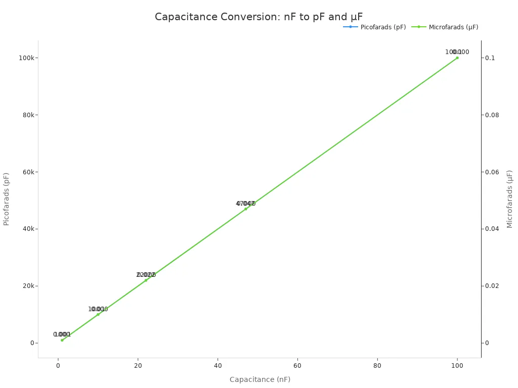
While converting capacitance units on paper, count your zeros carefully. A basic 10 nf part equals 10,000 pF or 0.01 µF. In a similar way, a 100 nf board part equals 0.1 µF. Converting capacitance units carefully stops part mistakes on factory assembly lines. Modern part makers print these capacitor values on datasheets using clear EIA number codes. Spotting these simple capacitor values helps you design steady working hardware. Always check your exact nf circuit needs before buying any new parts.
Reading Capacitor Codes and Markings
Small components often lack space for long printed labels. You read short numerical codes on each tiny capacitor to confirm electrical values. Understanding how to check a nanofarad in capacitors allows you to select correct parts instantly.
Decoding 3-Digit EIA Capacitance Codes
Manufacturers use the standard three-digit EIA numerical system to print a compact capacitance value on small parts. You read these digits to find capacitance fast:
-
Take the first two digits as base significant figures.
-
Multiply those base figures by ten raised to the power of the third digit to get picofarads.
-
Divide your picofarad result by 1,000 to get nanofarad units.
For example, the EIA code 104 translates through simple calculation steps:
| EIA Code | Base × 10^multiplier | pF | nF |
|---|---|---|---|
| 151 | 15 × 10^1 | 150 pF | 0.15 nF |
| 102 | 10 × 10^2 | 1,000 pF | 1 nF |
| 103 | 10 × 10^3 | 10,000 pF | 10 nF |
| 104 | 10 × 10^4 | 100,000 pF | 100 nF |
| 223 | 47 × 10^2 | 4,700 pF | 4.7 nF |
Code 104 equals 100 nF or 0.1 µF. You can convert any nf code to pF using this exact method. Recognizing code numbers helps you audit board layouts and standard capacitor values quickly.
Identifying Tolerance and Voltage Ratings
Standard part families follow preferred value lines called the e-series. You match your circuit needs against standard e-series options like E6, E12, or E24 e-series standards.
| Series | Values per decade | Preferred nF values |
|---|---|---|
| E6 e-series | 6 | 1.0, 1.5, 2.2, 3.3, 4.7, 6.8 nF |
| E12 e-series | 12 | 1.0, 1.2, 1.5, 1.8, 2.2, 2.7, 3.3, 3.9, 4.7, 5.6, 6.8, 8.2 nF |
| E24 e-series | 24 | 1.0, 1.1, 1.2, 1.3, 1.5, 1.6, 1.8, 2.0, 2.2, 2.4, 2.7, 3.0, 3.3, 3.6, 3.9, 4.7, 5.1, 5.6, 6.2, 6.8, 7.5, 8.2, 9.1 nF |
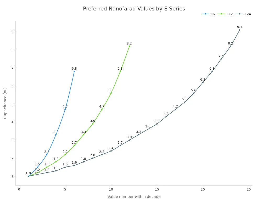
These standard e-series values repeat every decade. A 4.7 nf capacitor belongs to the E6 e-series line. A 47 nf capacitor or 470 nf capacitor uses the exact same e-series base scaling. Standard e-series tables simplify your choices among common capacitor values. You find ideal e-series choices across all standard capacitor values.
| Aspect | Marking Indication | Details |
|---|---|---|
| Tolerance Letters | J, K, M, Z | J = ±5%, K = ±10%, M = ±20%, Z = +80/-20% |
| Voltage Rating | VR or WV | Common ratings: 6.3V, 10V, 16V, 25V, 50V, 100V |
Suffix letters show tolerance ratings directly after numbers. A 100K code means a 100 pF capacitor with ±10% tolerance. Working voltage (WV) or voltage rating (VR) defines maximum circuit limits safely. Small 0402 or 0603 packages support 6.3V to 25V ratings. Larger 1206 packages support 50V to 100V ratings. Checking these specs ensures your selected capacitor operates reliably under load.
Key Circuit Applications for nF Capacitors
Noise Filtering and Signal Coupling
You place nf capacitors into board designs for critical signal tasks in filtering circuit networks. Active low-pass filters use a nanofarad component to redirect unwanted high-frequency noise directly to ground. Reactance drops as frequency rises. This action cleans line power during power supply filtering and aids ic decoupling near sensitive chips. Decoupling capacitors perform decoupling tasks to stabilize continuous voltages. You compute cutoff points in plain text with the formula fc = 1/(2πRC). Proper power supply filtering keeps sensitive stages quiet.
You also use specific capacitor values for AC signal coupling in audio circuit design:
-
100 nf: Passes AC signals while blocking DC in general audio stages.
-
10–47 nf: Couples microphone audio signals to an amplifier.
-
33 nf: Handles full-range audio signal coupling from 20 Hz to 20 kHz.
These general capacitor applications block steady direct currents while preserving alternating signals across stages. You maintain clean audio signals by matching proper capacitor values to input impedances. Nanofarad capacitance helps maintain strong signal integrity.
Driver and Energy Storage Applications
You pick nf components to manage precise timing tasks and energy storage roles in timing circuit networks. In timing networks, precision capacitance sets fixed oscillator frequencies. A 47 nf capacitor paired with a 1 kΩ resistor produces a ~21 kHz square wave in a 555 timer multivibrator. A 100 nf capacitor paired with a 10 kΩ resistor creates a ~1 ms delay in a monostable multivibrator. Proper timing stability prevents timing drift in critical circuit applications. Standard capacitor values deliver repeatable delays.
Energy buffering inside driver circuits requires steady capacitance performance. You choose a 10 nf C0G ceramic capacitor part as a sample-and-hold buffer inside an LED driver application. This setup drops voltage by only ~30 µV/ms to prevent visible LED flicker. Leaky 100 nf X7R parts cause visible droop under the same conditions. Engineers select capacitor values based on leakage limits. Smart circuit applications rely on clean ic decoupling, reliable power supply filtering, and steady nf choices to stabilize energy delivery in any power supply circuit layout. Another nanofarad component ensures low ripple across the load.
Selection Guidelines for nF Capacitors
Choosing the right nf capacitors requires clear rules for high-frequency circuit boards. Making smart capacitor selection choices prevents unexpected circuit failures. Careful capacitor selection helps you balance board size, total cost, and voltage limits in all your nf designs. You must check key operating features to pick the right capacitor for your system.
Comparing Dielectric Material Types
Begin your dielectric selection by matching circuit goals with standard material types. Class 1 C0G components give you stable performance without any aging effects over time. These non-polar ceramic components work great for high-frequency signal applications. Class 2 dielectrics like X7R pack more capacitance into tiny spaces for general energy storage. But Class 2 dielectrics drop in capacitance when exposed to DC bias voltages.
For Class II ceramic capacitors, choose a voltage rating 1.5× to 2× the maximum operating voltage. This improves reliability and reduces DC-bias capacitance loss. Always confirm the actual capacitance at the operating voltage from the capacitance-versus-DC-bias curve before accepting the printed value.
Finding the right capacitance means picking preferred capacitor values straight from standard e-series tables. The standard e-series framework organizes basic capacitor values into neat steps. You can easily find a 10 nf part for your nf filtering needs using standard e-series lists. Using these common e-series options lowers your overall building costs.
Evaluating ESR and Temperature Stability
You should always measure equivalent series resistance and self-resonance while running lab tests. Keeping equivalent series resistance low stops parts from getting too hot in power supplies. Small nanofarad MLCCs reach much higher self-resonant frequencies than large bulk capacitors. A 100 nf ceramic capacitor gives you awesome high-frequency filtering during ic decoupling at power pins. These nf MLCCs keep line voltages steady through quick power shifts.
| Dielectric type | Operating temperature range | Capacitance drift |
|---|---|---|
| C0G (Class 1) | -55°C to +125°C | 0 ±30 ppm/°C |
| X7R (Class 2) | -55°C to +125°C | ±15% |
| X5R (Class 2) | -55°C to +85°C | ±15% |
Heat shifts change your actual capacitance value while circuits are running. An X7R nanofarad device can drift by ±15% across its full operating temperature range. X5R parts only hold that ±15% limit up to 85°C. Always check temperature limits before finalizing your target capacitance value. Pick the right capacitor to ensure reliable nf decoupling even under hot conditions. Careful capacitor selection keeps your whole nf circuit working smoothly.
Handling nf capacitors takes straightforward actions to protect your board. First, you read the component style and decode numeric markings. Next, you check unit conversion by multiplying nanofarad values by 1,000 for pF. Finally, you verify correct circuit polarity and check tolerance letters before testing.
Smart capacitor selection requires matching dielectric materials with circuit temperature needs. Class 1 C0G parts offer high stability for timing tasks. Class 2 X7R materials supply higher capacitance for broad noise filtering applications.
Always select a capacitor with a voltage rating at least 20-30% higher than the circuit’s top voltage for safety.
Use this final selection checklist to choose the correct capacitor for your hardware project:
-
Find target nominal nanofarad in capacitors for your specific applications.
-
Review DC-bias, temperature drift, and ESR curves.
-
Confirm case size, land pattern, and voltage limits before final placement.

Written by Jack Elliott from AIChipLink.
AIChipLink, one of the fastest-growing global independent electronic components distributors in the world, offers millions of products from thousands of manufacturers, and many of our in-stock parts is available to ship same day.
We mainly source and distribute integrated circuit (IC) products of brands such as Broadcom, Microchip, Texas Instruments, Infineon, NXP, Analog Devices, Qualcomm, Intel, etc., which are widely used in communication & network, telecom, industrial control, new energy and automotive electronics.
Empowered by AI, Linked to the Future. Get started on AIChipLink and submit your RFQ online today!
Frequently Asked Questions
How do you convert an nf capacitor value to pF?
Multiply your nanofarad figure by 1,000 to find picofarads. As an example, a 10 nf part equals 10,000 pF. Shifting your decimal dot three spots right delivers the proper picofarad total fast.
What does the 104 code mean on a ceramic capacitor?
The 104 stamp stands for 100 nf or 0.1 µF. Initial digits 1 and 0 set your base number 10. Multiplying 10 by 10^4 picofarads yields full electrical storage capacity.
Why should you choose a C0G dielectric for your nf circuit?
Type 1 C0G materials offer stable thermal behavior without performance loss over time. Use a C0G nf element when building exact timing loops. Type 2 X7R options handle wide signal noise cleanup instead.
How do you check tolerance letters on an nf capacitor?
Look for the trailing alpha character following its numerical marking. The letter J signals a ±5% range window. Letter K designates ±10% variation, whereas M represents a ±20% limit. Inspecting this code guarantees proper component execution.