Table of Contents
- Introduction
- 1.0 Capacitor Polarity Symbols and Identification
- 2.0 Electrolytic Capacitor Markings Decoded
- 3.0 Capacitor Value Codes and Rating Systems
- 4.0 Ceramic Capacitor Identification Guide
- 5.0 Advanced Capacitor Rating Symbols
- 6.0 Failure Detection and Warning Signs
- Conclusion
Introduction
Are you staring at a circuit board wondering what those cryptic capacitor signs and markings actually mean? You're not alone. Understanding capacitor symbols, polarity markings, and value codes is essential for anyone working with electronics, yet it remains one of the most confusing aspects for both beginners and experienced technicians.
Here's a startling fact: According to industry data from 2024, over 60% of electronic circuit failures are attributed to incorrect capacitor identification and installation. Whether you're troubleshooting a power supply, designing a circuit, or simply trying to replace a failed component, knowing how to read capacitor markings can save you time, money, and frustration.
In this comprehensive guide, you'll master every aspect of capacitor identification – from basic polarity symbols to advanced failure detection techniques. We'll decode electrolytic capacitor markings, explain ceramic capacitor codes, and show you how to spot warning signs before components fail. By the end of this article, you'll confidently identify any capacitor and understand exactly what those mysterious markings tell you about performance, ratings, and reliability.
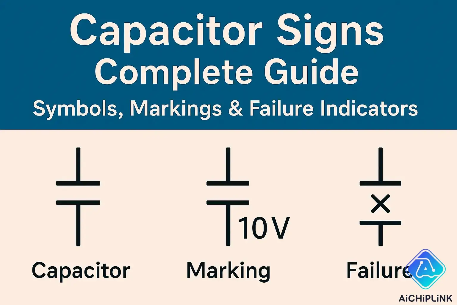
1.0 Capacitor Polarity Symbols and Identification
Understanding capacitor polarity symbols is absolutely critical for safe and successful circuit assembly. Getting polarity wrong can lead to component failure, circuit damage, or even safety hazards. Let me show you exactly how to identify positive and negative terminals on different capacitor types.
1.1 Positive and Negative Terminal Markings
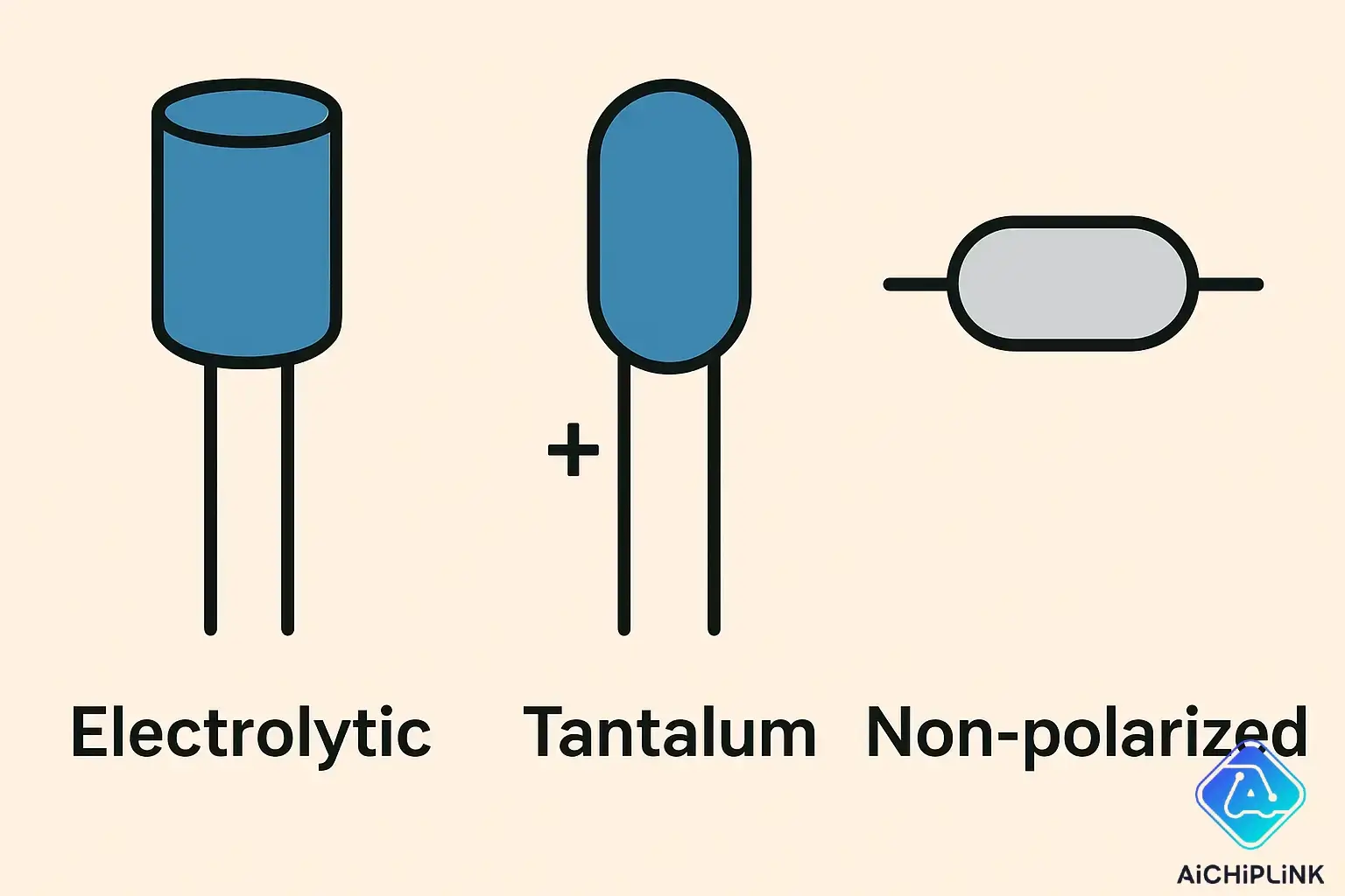
Different capacitor types use distinct polarity marking systems. Here's what to look for on each type:
Electrolytic Capacitors:
- Negative stripe: Dark band with minus (-) symbols running along the negative side
- Arrow indicators: Triangular arrows pointing toward the negative terminal
- Shorter lead: The negative terminal typically has a shorter wire lead
- Indentation: Small notch or indent near the negative terminal
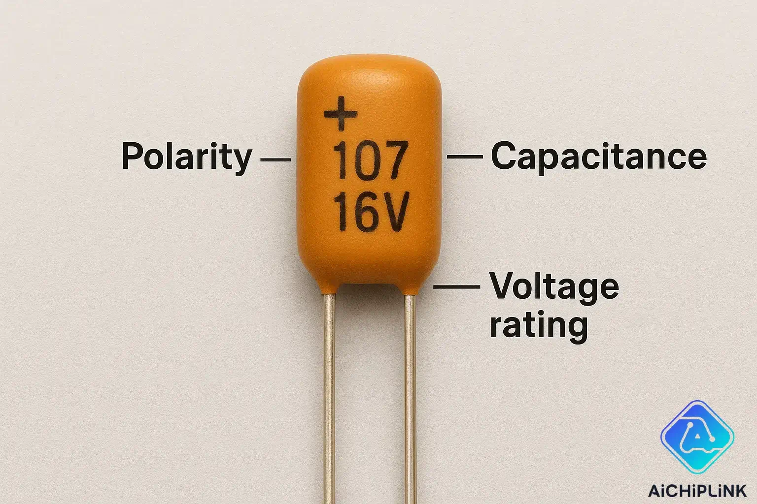
Tantalum Capacitors:
- Plus (+) marking: Positive terminal clearly marked with a plus sign
- Colored band: Often a colored stripe indicates the positive end
- Bevel edge: Chamfered corner typically indicates the positive terminal
- Dot marking: Small dot or line near the positive terminal
Film and Ceramic Capacitors:
- No polarity: These are non-polarized and can be installed in either direction
- No markings needed: Polarity symbols are absent because orientation doesn't matter
"The most expensive mistake in electronics is assuming a capacitor is non-polarized when it actually has polarity. Always check twice before connecting power."
1.2 Polarity Identification Methods
When capacitor markings are unclear or worn, use these proven identification methods:
-
Visual Inspection Method:
- Look for any minus (-) signs, even if faded
- Check for color differences in terminal markings
- Examine the capacitor body for asymmetrical features
-
Lead Length Method:
- Measure lead lengths if original leads are intact
- Negative lead is typically shorter on radial capacitors
- This method works best on new, unused components
-
Multimeter Testing:
- Use diode test mode on your multimeter
- Forward bias will show higher capacitance reading
- Reverse the probes to confirm polarity identification
For comprehensive capacitor selection guidance, visit our electronic components catalog for the latest inventory and specifications.
2.0 Electrolytic Capacitor Markings Decoded
Electrolytic capacitor markings contain crucial information about voltage ratings, capacitance values, and operating characteristics. Learning to decode these markings accurately is essential for proper component selection and replacement.
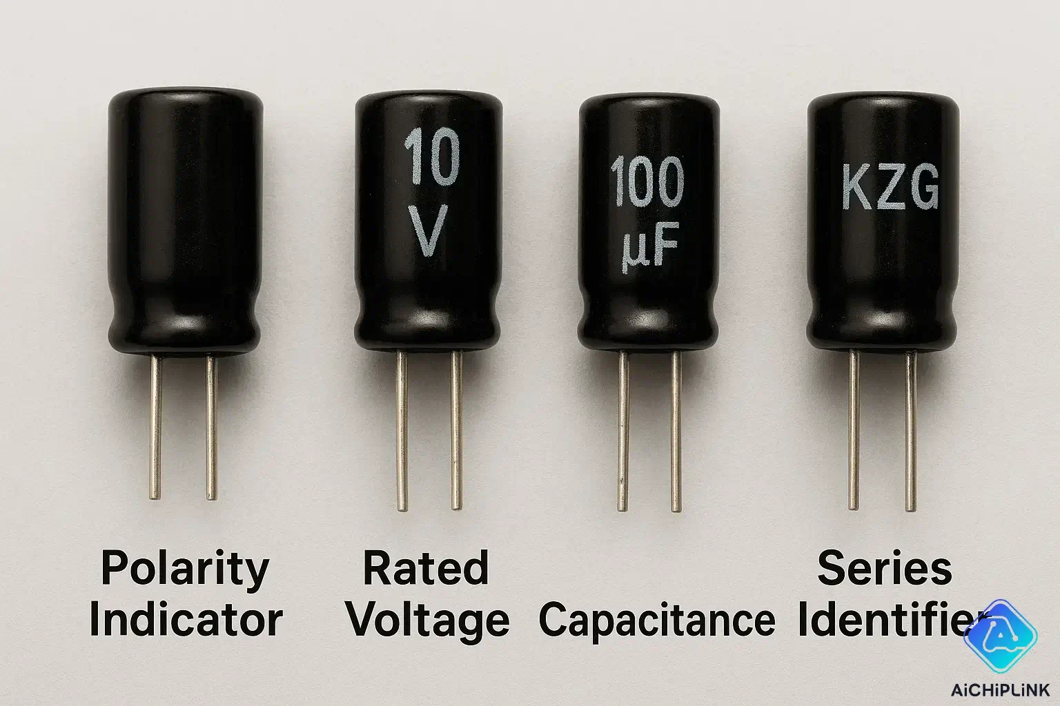
2.1 Voltage and Capacitance Markings
The primary markings on electrolytic capacitors tell you everything you need for safe operation:
| Marking Type | Example | Meaning | Critical Notes |
|---|---|---|---|
| Voltage Rating | 25V, 450V | Maximum safe voltage | Never exceed this value |
| Capacitance Value | 1000µF, 220µF | Storage capacity | Measured in microfarads |
| Tolerance | ±20%, ±10% | Accuracy range | Typical for electrolytics |
| Temperature Rating | 85°C, 105°C | Maximum operating temp | Higher is better for reliability |
| Ripple Current | 1.2A, 850mA | Maximum AC current | Critical for power supplies |
Reading Examples:
- "1000µF 25V" = 1000 microfarad capacitance, 25 volt maximum
- "220µF/450V 85°C" = 220µF, 450V rated, 85°C maximum temperature
- "47µF 16V ±20%" = 47µF capacitance with 20% tolerance at 16V maximum
2.2 Manufacturer Date Codes
Understanding manufacturer date codes helps you assess component age and reliability:
Common Date Code Formats:
- YYWW format: 2412 = 12th week of 2024
- Month/Year format: 0824 = August 2024
- Julian date: Day number of the year (1-365)
Age Assessment Guidelines:
- 0-2 years old: Excellent reliability, full specifications
- 3-5 years old: Good condition, monitor for drift
- 5-10 years old: Check ESR values, consider replacement
- Over 10 years: High failure risk, proactive replacement recommended
According to recent industry studies, electrolytic capacitors show significant performance degradation after 7-10 years of service, with failure rates increasing exponentially after this period.
3.0 Capacitor Value Codes and Rating Systems
Decoding capacitor value codes can seem overwhelming, but once you understand the systems, reading any capacitor becomes straightforward. Different capacitor types use different coding methods, and mastering these codes is essential for accurate component identification.
3.1 Numeric Code Systems
The most common numeric coding system uses a three-digit format that's surprisingly logical once you know the rules:
Three-Digit Code System:
- First two digits: Significant figures
- Third digit: Number of zeros to add
- Result: Value in picofarads (pF)
| Code | Calculation | Value | Unit Conversion |
|---|---|---|---|
| 104 | 10 + 0000 | 100,000 pF | 0.1 µF |
| 223 | 22 + 000 | 22,000 pF | 0.022 µF |
| 475 | 47 + 00000 | 4,700,000 pF | 4.7 µF |
| 102 | 10 + 00 | 1,000 pF | 1 nF |
Special Cases:
- Codes under 100: Direct value in pF (e.g., "47" = 47 pF)
- Decimal codes: Use "R" for decimal point (e.g., "4R7" = 4.7 pF)
- Letter suffixes: Indicate tolerance (J = ±5%, K = ±10%, M = ±20%)
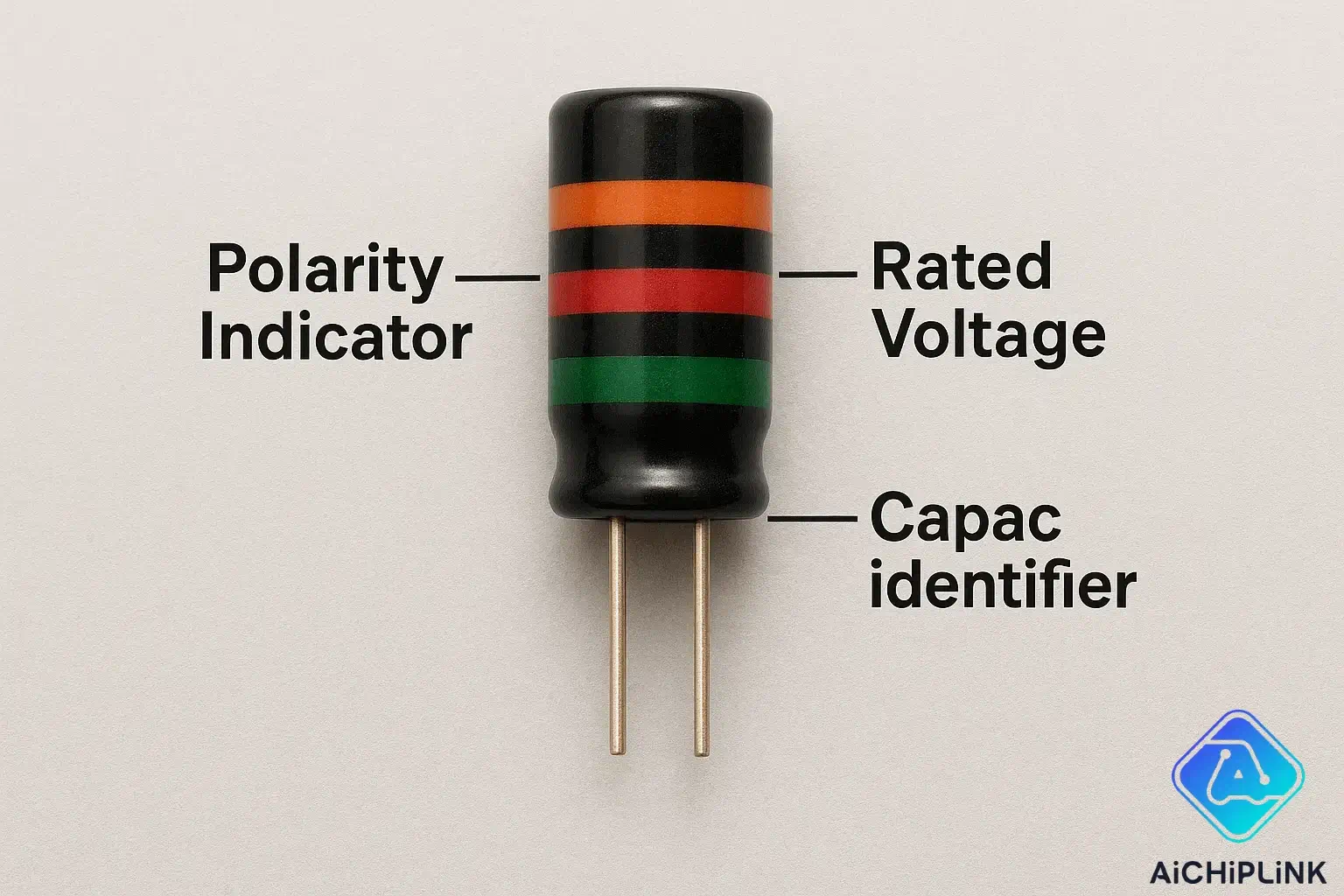
3.2 Color Code Interpretation
While less common today, color coding systems still appear on some capacitor types:
Standard Color Code Values:
- Black: 0
- Brown: 1
- Red: 2
- Orange: 3
- Yellow: 4
- Green: 5
- Blue: 6
- Violet: 7
- Gray: 8
- White: 9
Reading Method:
- First band: First significant digit
- Second band: Second significant digit
- Third band: Multiplier (number of zeros)
- Fourth band: Tolerance (if present)
For additional information on capacitor specifications, refer to IEEE capacitor standards which define industry-standard marking practices.
4.0 Ceramic Capacitor Identification Guide
Ceramic capacitor identification presents unique challenges due to their small size and varied marking systems. These components are ubiquitous in modern electronics, making accurate identification skills absolutely essential for any technician or engineer.
4.1 Size and Type Markings
Ceramic capacitors use standardized size codes that indicate both physical dimensions and typical capacitance ranges:
Common Size Codes:
- 0402: 0.4mm × 0.2mm - typically 1pF to 1nF
- 0603: 0.6mm × 0.3mm - typically 1pF to 10nF
- 0805: 0.8mm × 0.5mm - typically 1pF to 100nF
- 1206: 1.2mm × 0.6mm - typically 100pF to 10µF
- 1210: 1.2mm × 1.0mm - high-capacitance applications
Type Classifications:
- Class I (C0G/NP0): Ultra-stable, low loss, temperature compensation
- Class II (X7R/X5R): Higher capacitance, moderate stability
- Class III (Y5V/Z5U): Highest capacitance, significant temperature variation
4.2 Temperature Coefficient Codes
Understanding temperature coefficient codes is crucial for applications requiring stable performance across temperature ranges:
| Code | Temperature Range | Capacitance Change | Applications |
|---|---|---|---|
| C0G/NP0 | -55°C to +125°C | ±30ppm/°C | Precision timing, filters |
| X7R | -55°C to +125°C | ±15% | General purpose, decoupling |
| X5R | -55°C to +85°C | ±15% | Consumer electronics |
| Y5V | -30°C to +85°C | +22% to -82% | Non-critical applications |
Decoding the Codes:
- First character: Low temperature limit
- Second character: High temperature limit
- Third character: Maximum capacitance change
"Choosing the wrong temperature coefficient can cause circuit instability in precision applications. Always verify the temperature requirements before selecting ceramic capacitors."
Explore our comprehensive ceramic capacitor inventory for professional-grade components with detailed specifications.
5.0 Advanced Capacitor Rating Symbols
Advanced capacitor rating symbols provide critical information about safe operating limits, performance characteristics, and application suitability. Understanding these symbols prevents component failures and ensures optimal circuit performance.
5.1 Capacitor Voltage Rating Symbols
Voltage rating symbols indicate the maximum safe operating voltage under different conditions:
Standard Voltage Markings:
- V or VDC: DC voltage rating
- VAC: AC voltage rating (typically lower than DC)
- WVDC: Working Voltage DC (conservative rating)
- Surge: Maximum surge voltage capability
- Test: Factory test voltage (higher than working voltage)
Critical Voltage Guidelines:
- Derating Rule: Use capacitors rated at least 50% higher than circuit voltage
- AC vs DC: AC ratings are significantly lower due to heating effects
- Surge Protection: Consider transient voltages in power supply applications
- Temperature Effects: Voltage ratings decrease at high temperatures
5.2 Tantalum Capacitor Markings
Tantalum capacitor markings use specialized coding systems due to size constraints:
Standard Marking Format:
- Capacitance: Usually in µF (e.g., "10" = 10µF)
- Voltage: Letter code system (A=10V, B=16V, C=25V, D=35V, E=50V)
- Case Size: Letter indicating physical dimensions
- Polarity: Stripe or "+" symbol for positive terminal
Example Interpretations:
- "22C" = 22µF, 25V rating
- "47B" = 47µF, 16V rating
- "100A" = 100µF, 10V rating
Safety Warning: Tantalum capacitors can fail catastrophically if overvoltaged. Always verify voltage ratings and use appropriate derating factors.
According to IPC standards for electronic assemblies, proper voltage derating extends capacitor life by an average of 300% in typical operating environments.
6.0 Failure Detection and Warning Signs
Recognizing capacitor failure signs early can prevent costly circuit damage and system downtime. Failed capacitors are responsible for approximately 40% of power supply failures, making early detection skills invaluable for maintenance and troubleshooting.
6.1 Bad Capacitor Symptoms
Visual failure indicators are often the first signs of capacitor problems:
Physical Warning Signs:
- Bulging or swelling: Top or sides of capacitor appear rounded or distorted
- Leaking electrolyte: Brown or white crystalline deposits around base
- Vent opening: Safety vent has opened, releasing pressure
- Discoloration: Heat damage causing color changes on the body
- Cracked case: Physical damage to capacitor housing
Electrical Symptoms:
- High ESR: Equivalent Series Resistance above specifications
- Low capacitance: Measured value significantly below rating
- High leakage: Excessive current flow when not charging/discharging
- No capacitance: Complete loss of energy storage capability
- Intermittent operation: Sporadic electrical connection
Performance Impact:
- Power supplies: Increased ripple, poor regulation, overheating
- Audio circuits: Distortion, reduced bass response, noise
- Timing circuits: Incorrect timing, frequency drift
- Motor starting: Difficulty starting, reduced torque, overheating
6.2 Capacitor Tolerance Codes
Understanding tolerance codes helps you select appropriate replacement components:
| Code | Tolerance | Typical Applications |
|---|---|---|
| J | ±5% | Precision timing, filters |
| K | ±10% | General purpose applications |
| M | ±20% | Non-critical circuits |
| N | ±30% | Power supply filtering |
| P | +100%, -0% | Minimum capacitance critical |
Testing Procedures:
- Visual inspection: Look for obvious physical damage
- ESR testing: Use specialized ESR meter for accurate results
- Capacitance measurement: Compare to rated value
- Leakage testing: Check for excessive current flow
- Ripple current testing: Verify current handling capability
This video demonstrates professional techniques for testing capacitors and identifying failure modes in real-world applications.
Find replacement capacitors and testing equipment in our electronic components section with same-day shipping available.
Conclusion
Understanding capacitor signs and markings is an essential skill that separates professional technicians from amateurs. Throughout this comprehensive guide, we've decoded everything from basic polarity symbols to advanced failure detection techniques, giving you the knowledge to confidently work with any capacitor type.
The key takeaways include recognizing polarity markings on electrolytic and tantalum capacitors, decoding value codes using numeric and color systems, and identifying early warning signs of component failure. Whether you're troubleshooting power supplies, designing circuits, or maintaining electronic equipment, these skills will serve you throughout your career.
As electronic systems become more complex and miniaturized, accurate capacitor identification becomes even more critical. Components are smaller, markings are more cryptic, and the consequences of errors are more severe. The techniques and knowledge you've gained here provide a solid foundation for handling current and future challenges in electronics.
Ready to upgrade your component inventory with reliable, properly marked capacitors? Visit our professional capacitor collection for expert recommendations and technical support. Our team is ready to help you select the right components for your specific applications and ensure your projects achieve optimal performance and reliability.
Frequently Asked Questions
How do you identify capacitor polarity?
Look for polarity markings on the capacitor body. Electrolytic capacitors typically have a minus (-) stripe indicating the negative terminal, while tantalum capacitors show a plus (+) sign for the positive terminal. The negative lead is often shorter on radial capacitors. Non-polarized capacitors like ceramic and film types can be connected in either direction.
What do the numbers on a capacitor mean?
The numbers indicate capacitance value, voltage rating, and tolerance. For example, "470µF 25V" means 470 microfarads capacitance with a maximum 25-volt rating. Three-digit codes like "104" represent 10 + 0000 = 100,000 picofarads (0.1µF). Always check both capacitance and voltage ratings when selecting replacements.
How can you tell if a capacitor is failing?
Common failure signs include physical bulging or swelling, electrolyte leakage (brown/white deposits), high ESR readings, reduced capacitance values, and performance issues like increased ripple in power supplies. Use an ESR meter for accurate testing, as failing capacitors often maintain correct capacitance while developing high internal resistance.
What does ESR mean for capacitors?
ESR stands for Equivalent Series Resistance - the internal resistance that affects capacitor performance. Low ESR is critical for power supply filtering and high-frequency applications. Failed or aging capacitors typically show elevated ESR values, causing poor filtering performance and circuit heating even when capacitance appears normal.
Can you use a higher voltage capacitor as replacement?
Yes, using a higher voltage rating is safe and often recommended for improved reliability. However, ensure the physical size fits and the capacitance value matches. Higher voltage capacitors may have different ESR characteristics, so verify compatibility in critical applications like switching power supplies or audio circuits.