How to Master Circuit Components and Their Formulas
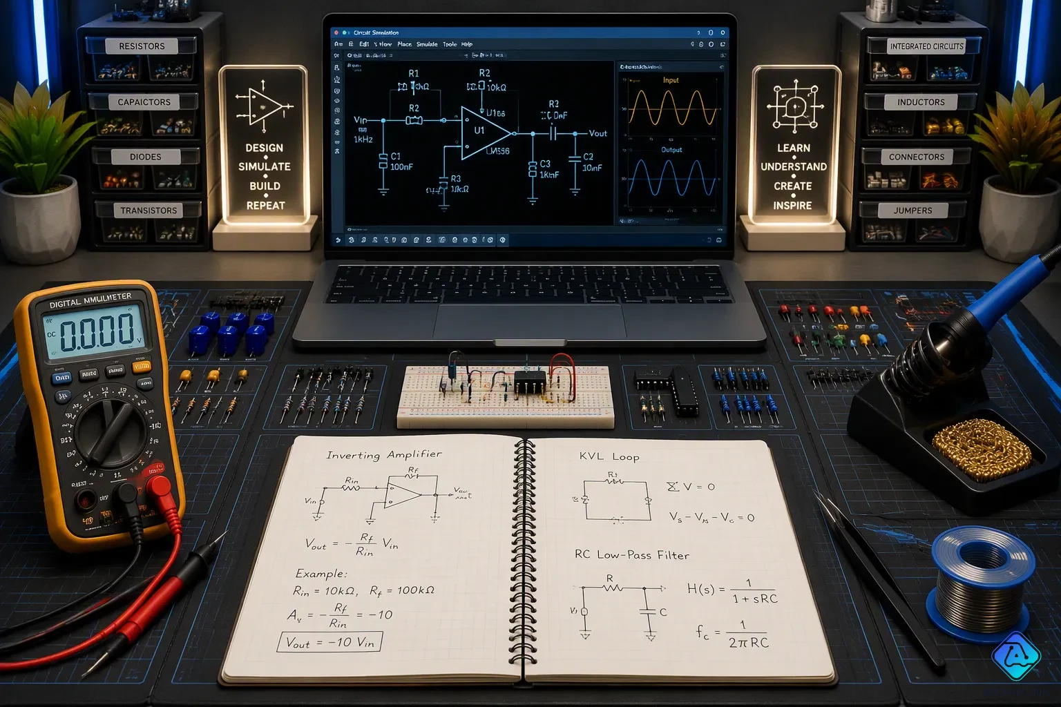
To master Circuit Components and Formulas, just follow three simple steps: learn what a component does, learn its main formula, then use it on a real circuit problem. In electrical engineering, think of voltage like water pressure, current like flow rate, and resistance like the pipe's narrowness. Sending current through a very resistive material is like pushing water through a pipe full of sand. This plumbing comparison shows that each component has predictable math. You will learn the key formulas for resistors, capacitors, inductors, diodes, and transistors, plus how to combine them in series and parallel. Focus on these steps, and you can solve any circuit problem with confidence.
Key Takeaways
-
Find out what each circuit part does and its main formula.
-
Use Ohm's Law (V = I × R) to find voltage, current, or resistance.
-
Use power formulas (P = V × I) to pick safe parts.
-
Connect parts in series and parallel with easy rules.
-
Use real circuits or simulation software to practice and build your skill.
Ohm's Law and Power Basics
Ohm's Law for Voltage, Current, and Resistance
Ohm's Law is the basis for studying any electric circuit. This easy rule says current goes up when voltage goes up, and goes down when resistance goes up. If you know two of the three values, you can find the third using V = I × R. That one link helps you follow voltage drops, check safety limits, and build real circuits, from tiny gadgets to big power systems.
You will use Ohm's Law in almost every electric circuit problem you face. Imagine a 9V battery pushing a 1kΩ resistor. The current is 9V divided by 1000Ω, which equals 0.009A, or 9mA. This math shows how a resistor holds back current in an electric circuit. Remember that heat changes and non-linear parts can bend the rule, but Ohm's Law is still your starting point for any electric circuit.
Power and Energy Formulas
Power shows how fast a component uses or stores energy. The main equation is P = V × I. You can rearrange it into two handy forms: P = I² × R and P = V² / R. In the 9V, 1kΩ example, the power is 9V × 0.009A, or 0.081W. That number helps you choose a resistor with a safe wattage rating.
Energy storage works in a similar way. A capacitor stores energy in its electric field, and the formula is E = 0.5 × C × V². An inductor stores energy in its magnetic field, and the formula is E = 0.5 × L × I². Both equations come from adding up power over time. These formulas matter in any electric circuit that turns on and off, because stored energy has to go somewhere. Practice these power and energy rules with Ohm's Law, and you get the tools to study almost any electric circuit.
Basic Electronic Components and Formulas
Basic electronic components are the passive building blocks of every circuit: resistors, capacitors, and inductors. These three types of electronic components do not make signals stronger. They shape voltage and current instead. You can master circuit components and formulas by learning what each part does and which equation describes it.
Resistors: Limiting Current and Dividing Voltage
Resistors work against current flow. Their main formula is V = I × R, the same Ohm's Law you already know. You use resistors for two main jobs: limiting current and dividing voltage. A voltage divider uses two resistors in series to make a smaller output voltage from a larger input. Current limiting protects sensitive parts, such as LEDs.
Color codes tell you a resistor's value and tolerance. A four-band resistor with Yellow, Violet, Red, and Gold works like this: Yellow equals 4, Violet equals 7, so the significant digits are 47. Red is a multiplier of 100, giving 4,700 ohms, or 4.7 kΩ. Gold means plus or minus 5 percent, so the real value falls between 4.465 kΩ and 4.935 kΩ. Five-band resistors add a third digit. Six-band resistors add a temperature coefficient band.
Practical designs show how resistors limit current. A red LED on a 5 V supply uses a 330 Ω resistor to hold current near 10 mA. A blue LED on the same supply needs 220 Ω. A relay driver with a 5 V microcontroller uses a 1 kΩ base resistor. These examples show why resistor selection parameters matter in real work.
Capacitors and Inductors: Storing Energy
Capacitors store energy in an electric field. The charge formula is Q = C × V, where Q is in coulombs, C is in farads, and V is in volts. The energy formula is E = 0.5 × C × V², in joules. Try a 100 µF capacitor at 12 V. First convert to farads: 100 divided by 1,000,000 equals 0.0001 F. Charge equals 0.0001 F times 12 V, or 0.0012 C, which is 1.2 mC. Energy equals 0.5 times 0.0001 F times 144, or 0.0072 J, which is 7.2 mJ. The half factor appears because a capacitor's voltage climbs from zero as it charges. Capacitor selection parameters include voltage rating and tolerance.
Inductors store energy in a magnetic field. Their voltage relation is V = L × (di/dt), where L is in henries and di/dt is the rate of current change. Energy follows E = 0.5 × L × I². In a 12 V to 3.3 V buck converter running at 500 kHz, full energy storage needs about 4.8 µH. Designers often pick 15 µH instead, keeping ripple current between 30 and 60 percent of the average. Inductor selection parameters include saturation current and tolerance. Both capacitors and inductors release stored energy when a circuit switches off, so plan for that path.
Essential Electrical Components: Diodes and Transistors
Essential electrical components are the active parts that control current flow and make signals stronger. Unlike passive parts, they need power from outside to work. They can change voltage or current, add gain, and create oscillations. Transistors and integrated circuits are common examples. This difference shapes how you study any circuit that uses them.
Diodes: One-Way Current Flow
Diodes let current pass one way and block it the other way. The Shockley equation shows this action: I = I_s × (e^(V/(n×V_T)) - 1). In forward bias, the voltage term gets large next to the thermal voltage, so the -1 becomes tiny. The relation becomes a simple exponential curve. For hand calculations, you can swap the full equation for a fixed forward-voltage drop. A silicon diode drops about 0.7 V, a Schottky or germanium diode drops about 0.3 V, and an LED uses its datasheet value. A 5 V rail through a silicon diode leaves about 4.3 V for the load.
LEDs are special diodes that turn electrical energy into light. Most common LEDs need a forward voltage between about 1.2 V and 3.6 V, with a forward current rating near 10 mA to 30 mA. Red LEDs usually drop 1.7 V to 2.2 V, while blue and white LEDs drop 3.2 V to 4.0 V. Forward voltage shifts only about 60 mV for a tenfold current change, so a low-current test often predicts performance at higher current. Temperature also matters, shifting forward voltage by about -1 to -3 mV per kelvin. When you pick diode selection parameters, check the forward voltage at your intended test current and confirm the maximum current rating.
Transistors: Amplification and Switching
Transistors make signals stronger and work as switches. The current gain equation is β = I_C / I_B, where I_C is collector current and I_B is base current. For small-signal transistors, β is usually greater than 50, and general-purpose transistors often fall between 20 and 200. Suppose β equals 100 and I_B equals 20 µA. Then I_C equals 100 × 20 µA, or 2 mA. That result tells you how much current the transistor can control at the collector.
A transistor works in two main modes. In amplifier mode, it boosts a small input signal into a larger output. In switch mode, it jumps between fully off and fully on, like a relay. Active components also include triode vacuum tubes and tunnel diodes, though transistors dominate modern designs. When you review transistor selection parameters, confirm the gain range, the maximum collector current, and the power dissipation limit. Pair these checks with the formulas above, and you can predict how essential electrical components behave in any circuit.
Series, Parallel, and Integrated Circuit Rules
Series and Parallel Combinations
You put basic electronic parts together with simple rules. In series, you add resistors and inductors directly. For capacitors in series, you add their reciprocals. In parallel, you add capacitors directly. For resistors and inductors in parallel, you add their reciprocals. These rules let you find one value that works for the whole group.
For parts in parallel, you find the total impedance using the reciprocal sum. The formula is 1/Z_total = 1/Z_1 + ... + 1/Z_n. For two parts, you can also use Z_total = (Z_1 x Z_2) / (Z_1 + Z_2).
For example, two 100 Ω resistors in parallel give 50 Ω. The total resistance is always less than the smallest resistor. With capacitors or inductors, the impedance changes based on reactance signs. In a parallel RLC circuit at resonance, XL equals XC. The reactances cancel each other, so the impedance Z equals just the resistance R.
| Property | Series RLC | Parallel RLC |
|---|---|---|
| Current | Same in all parts | Sum of each branch |
| Voltage | Add all drops | Same across all parts |
| Ohm's Law | V = I × Z | I = Y × V |
Use Ohm's law on the simplified circuit. First find the total current or voltage. Then go back to find each branch's value.
Supporting Components and Integrated Circuits
A circuit starts with a power source like a battery or AC line, a switch, and a load. The switch can be a mechanical type with contacts or an electronic type using a bipolar transistor.
Every electric circuit has a voltage source (like a cell or battery), switches, wires, and a load like a light bulb. The source pushes current through the load and back to ground.
An integrated circuit puts many parts onto one small silicon chip. Jack Kilby and Robert Noyce made the first one in the late 1950s. Today, ICs use ball grid arrays, wafer level chip scale packages, and chip-on-board assembly. These methods make ICs smaller and faster. ICs power smartphones, pacemakers, and self-driving car sensors. Learning circuit parts and formulas helps you understand any circuit, from a simple resistor to a complex IC.
Mastering circuit components and formulas takes three steps you can repeat. Figure out what each component does. Remember its main formula. Then use that formula on a real circuit. Keep these key formulas handy: Ohm's Law for voltage and current, power equations, capacitor charge and energy, inductor voltage and energy, the diode equation, and transistor gain equations. Practice with real circuit components or simulation software. Make your own formula sheet. Write down each formula, its units, and one example. Voltage and current formulas show up the most. Review them often. These circuit analysis actions turn knowledge into a skill that lasts.

Written by Jack Elliott from AIChipLink.
AIChipLink, one of the fastest-growing global independent electronic components distributors in the world, offers millions of products from thousands of manufacturers, and many of our in-stock parts is available to ship same day.
We mainly source and distribute integrated circuit (IC) products of brands such as Broadcom, Microchip, Texas Instruments, Infineon, NXP, Analog Devices, Qualcomm, Intel, etc., which are widely used in communication & network, telecom, industrial control, new energy and automotive electronics.
Empowered by AI, Linked to the Future. Get started on AIChipLink and submit your RFQ online today!
Frequently Asked Questions
What is the single most important formula to learn first?
Begin with Ohm's Law: V = I × R. Every other relationship is built on it. When you know two values, you can find the third. Practice it on a simple circuit until the math becomes easy.
How do I remember which components store energy?
Capacitors store energy in an electric field, and inductors store energy in a magnetic field. The capacitor formula is E = 0.5 × C × V². The inductor formula is E = 0.5 × L × I². Both use a half factor because charge builds up slowly.
Why do resistors and capacitors follow opposite rules in series and parallel?
Resistors add directly in series and add reciprocally in parallel. Capacitors do the opposite. Inductors act like resistors. These rules let you reduce any network to one value before you use Ohm's Law.
How do I pick a resistor for an LED?
Subtract the LED forward voltage from your supply voltage. Divide that difference by your target current. A red LED on 5 V with a 330 Ω resistor keeps current near 10 mA. Always check the resistor wattage rating.
Do I need to memorize the diode and transistor equations?
No. Use the simple forward-voltage model for most diode work. For transistors, remember β = I_C / I_B. Use the full Shockley equation only when you need precise exponential behavior. Real ics hide these details inside the chip anyway.