What is the difference between rated current and saturation current in inductors?
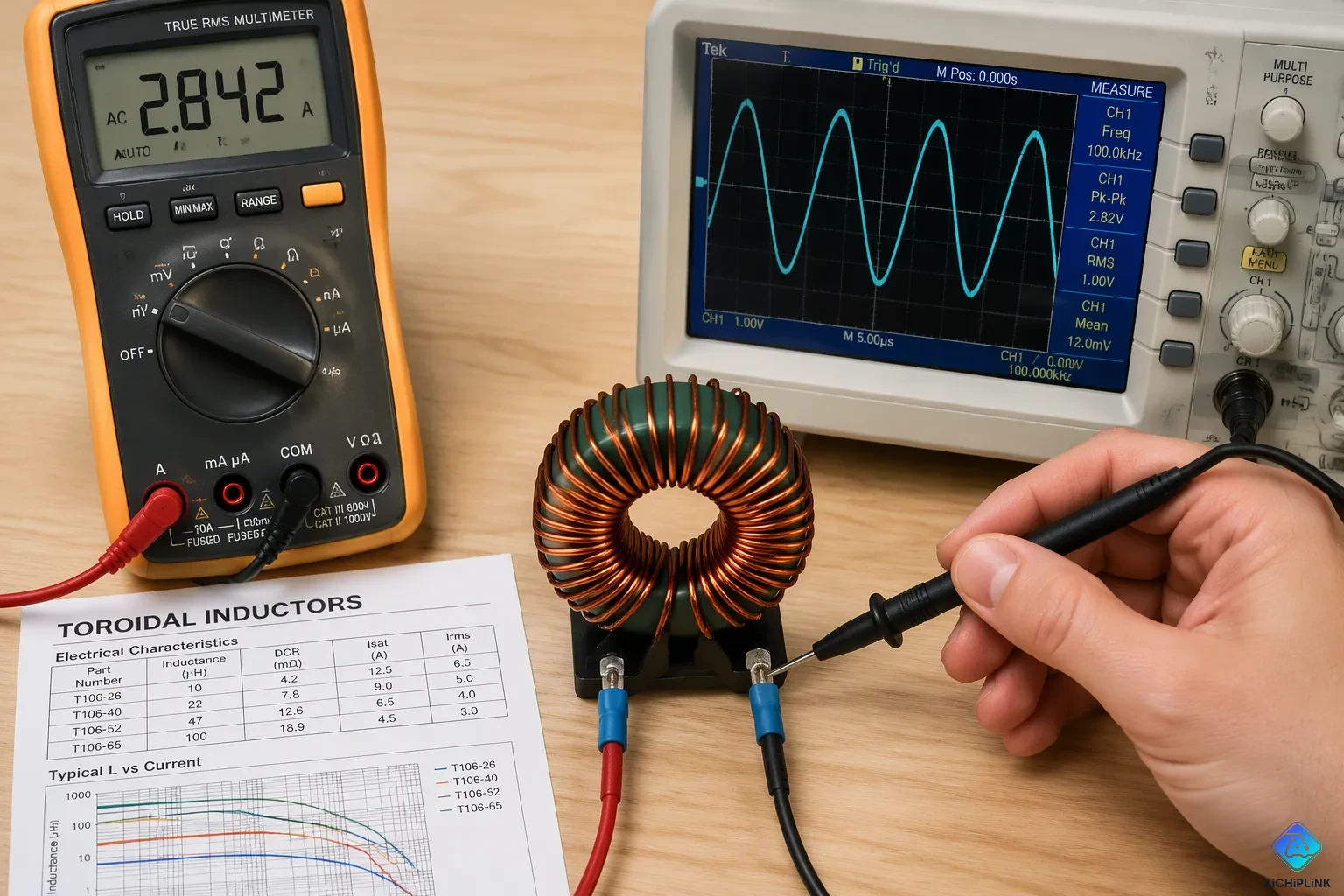
Rated current and saturation current describe two different limits in one component. Rated current is the highest continuous RMS current the winding can carry within a set temperature rise. This is a heat limit set by wire size and heat generation. Saturation current is the DC current at which inductance drops by a set percentage. This is a magnetic limit set by core material and magnetic path structure. Saturation current stays mostly independent of temperature. Rated current depends directly on heat in the winding. The difference between inductor rated current vs saturation current matters most in one commonly missed case: saturation current can fall below the rated RMS current. An inductor may run cool yet still saturate. This is why designers check both ratings. Understanding rated current vs saturation current prevents that mistake.
Key Takeaways
-
Rated current limits the heat in the winding. Saturation current limits the magnetic flux in the core.
-
Check both current ratings. The peak current must stay below the saturation current. The RMS current must stay below the rated current.
-
Keep peak current 20–30% below saturation current. This extra room protects against sudden current spikes.
-
An inductor can run cool and still saturate. Always check both ratings on the datasheet.
-
Going over the rated current makes the part overheat. Going over the saturation current makes the inductance drop.
Inductor Rated Current vs Saturation Current: Definitions
Thermal Limit vs. Magnetic Limit
Rated current is the highest RMS current a part can take, set by winding heat and temperature rise. Current through the copper resistance makes I²R losses, and those losses warm the part. A typical inductor runs in still air with no heat sink, and the test current rises until the temperature rise hits a set limit. That limit is usually 15°C for chip inductors and 40°C for power inductors. A 3.5 A rated current, for example, means the part reaches 65°C at 25°C ambient once steady state arrives.
Saturation current is the DC current that makes inductance drop by a set amount, often 10%, 20%, or 30% from the zero-bias value. So the definition of saturation current depends on the drop criterion a vendor picks. IEC 62024-2 and IEC 61007 define this point at 10%, 20%, or 30% drop, tested near 1 kHz with a DC bias sweep. Some vendors publish both the 10% and 30% levels to show the knee of the inductance-versus-current curve.
The rated current is the most current the inductor can handle nonstop without getting too hot. The saturation current is the current where the inductor's inductance begins to drop a lot.
Aspect Rated current Saturation current Limiting mechanism Heat from I²R losses Flux in the core Governing parameter Wire gauge and resistance Core material and magnetic path Temperature dependence Strong; derate at high ambient Weak; largely fixed Typical operating condition Continuous RMS current Peak or transient current
A simple analogy separates the two. Rated current is like the flow limit of a pipe, where too much flow strains the walls and builds heat. Saturation current is like the closing point of a valve, where the magnetic path stops passing flux and effective inductance collapses.
Saturation Current vs. Rated Current in Continuous and Peak Operation
The saturation current vs. rated current split maps onto two operating regimes. Continuous operation is limited by the average or RMS current, because heating follows the average real power dissipated. Peak operation is limited by the saturation current, because the flux swing follows the instantaneous current. In continuous conduction mode the inductor current never reaches zero, so peak currents stay modest and conduction losses stay low. In discontinuous mode the current falls to zero each cycle, and peak current can run much higher for the same average load.
A worked example makes the check concrete. An inductor carries 4 A average with about 0.81 A ripple. Peak current equals 4 A plus half the ripple, or roughly 4.41 A. RMS current equals about 4.01 A. A part with 7 A saturation current and 8 A DC current rating passes both checks: 7 A exceeds 4.41 A, and 8 A exceeds 4.01 A. Designers must also confirm that the saturation current of inductors exceeds the maximum IC current limit, since start-up and short-circuit events push peak current far above steady-state values. Magnetic saturation is a hard ceiling, and core saturation removes the margin a converter needs to stay stable.
Rated Current vs Saturation Current: Selecting an Inductor
Calculating RMS and Peak Currents
A good selection follows a set order. First, identify the circuit topology, because the output-to-inductor current relationship differs between buck, boost, and buck-boost stages. Second, find the average inductor current. A buck converter draws roughly the output current, while boost and buck-boost stages draw more. Third, calculate the ripple current, the AC part riding on the average. Fourth, compute the peak inductor current as the DC current plus half the ripple. With 10 A average and 3 A ripple, peak current equals 11.5 A. Fifth, estimate rms current, which sets copper loss and temperature rise. Sixth, compare both results against the current ratings. The rms current must stay under the inductor rated current, and the peak current must stay under the saturation current. Seventh, apply margins and derating. Eighth, check ambient temperature, airflow, and nearby heat sources, since inductor datasheet ratings assume specific test conditions. Finally, verify the design with a current probe and a thermal measurement.
The rms current needs careful attention. In an inductive path, impedance rises with frequency, so the fundamental component carries most of the rms current. A designer can size copper from the average plus low-order ripple without adding up an endless harmonic series.
Applying Design Margins
Margins protect against the unknowns a datasheet cannot capture. Keep the peak current at least 20–30% below the saturation current. A 3 A peak does not justify a part rated at exactly 3 A saturation current. The margin table below shows how flux utilization maps to risk.
| Status | Flux Utilization |
|---|---|
| Large margin | < 50% |
| Good margin | 50–75% |
| Moderate margin | 75–90% |
| Near limit | 90–100% |
| Saturation risk | > 100% |
Headroom on saturation current, not just steady-state current rating, is a key selection rule, because sudden load transients can push the core into saturation, collapsing inductance and making the converter's control loop unstable.
Derate the rated current for the real thermal environment. A typical power supply delivers full rated power to 50°C, then derates linearly to 50% of rated power at 70°C. Airflow shifts the derating start point: roughly 67°C with no airflow, about 85°C at 100 LFM, and about 95°C at 500 LFM. More airflow beyond 100 LFM gives only limited improvement. Derating percentages are cumulative, so a 150 W supply derated to 90% for low-line input and 50% for 70°C ambient delivers at most 67.5 W.
One case trips up many designs: inductor saturation current below the rated rms current. The part runs cool yet saturates on peaks. The fix is a larger core or a higher-saturation part, not a higher rated current alone. Check both numbers on the inductor datasheet before committing, and treat the peak current limit as a hard ceiling.
How Manufacturers Specify Inductor Saturation Current
Reading Datasheet Test Conditions
Vendors set inductor saturation current at a stated inductance-drop percentage. That drop point is often 10%, 20%, or 30% from the zero-bias value. The drop pattern changes with the magnetic path structure. Ferrites hold inductance well as current rises, then lose it suddenly at magnetic saturation. Powdered iron fades much more slowly but stays useful. A vendor's inductance versus dc bias current graph shows this shape directly, and the curve reveals where the knee sits.
Rated current follows a different rule. Vendors specify it at a stated temperature rise, such as 20°C or 40°C. The table below sums up the test conditions a designer should confirm on any inductor datasheet.
| Rating | Test condition stated | Key criterion |
|---|---|---|
| Rated current | Specified temperature rise | Temperature rise limit |
| Saturation current | DC bias applied | Inductance drop percentage |
| Caveats | Thermal tests may omit high-frequency winding effects | Frequency dependence |
| Conditions | PCB copper area, airflow, ambient, mounting | Ratings shift near actual circuit conditions |
Manufacturer definitions differ. TDK splits allowable current by dc bias versus temperature rise. Coilcraft uses inductance decrease for saturation current and temperature rise for rated current. So the way saturation current is measured depends on the vendor's stated method.
Consequences of Exceeding Each Rating
Going over the rated current causes overheating. Insulated conductors pass their temperature rating, and the insulation breaks down into conductive deposits. Leakage current then flows, adds heat, and arc tracking can follow. The heating spreads along the whole conductor length, not just one spot.
Going over saturation current causes inductance collapse. Effective inductance drops suddenly, so peak current spikes and the converter may lose stability. In coupled inductors, too much differential-mode current saturates the phases and the part loses effectiveness. Core saturation is a hard ceiling, and designers must check peak current against it.
Saturation current stays largely independent of temperature. Rated current must be derated at elevated ambient. Both current ratings are conditional, so check the stated limits before you finalize a selection.
Practical Guidelines by Application
Power Converters and EMI Filters
Buck, boost, and buck-boost stages all use the same checking steps. The designer compares peak current to saturation current and rms current to rated current. Peak current equals the average inductor current plus half the ripple. Rms current comes from the average and the ripple together. The table below sums up the three checks.
| Parameter | Requirement | Typical margin |
|---|---|---|
| Nominal inductance L | At or above the calculated minimum | Use nearest standard value |
| Saturation current (30% roll-off) | Above peak current | +20…30% recommended |
| Rated current (thermal limit) | Above rms current | Verify temperature rise curve |
A buck converter draws about the output current, so the rms current stays close to the load. A boost or buck-boost stage pulls a higher input current, so the rms current check gets tighter. In every topology, the inductor saturation current must be higher than the peak current limit. The datasheet should state the percentage by which inductance falls at a given dc bias. The peak limit may be fixed in monolithic parts or adjustable through external control MOSFETs.
EMI filters and energy-storage chokes split along the same line. Filter chokes usually carry small rms current, so thermal limits rarely bind; the magnetic limit dominates when common-mode or differential spikes arrive. Energy-storage chokes carry large continuous current, so the inductor rated current and its temperature rise curve drive the choice. A part that runs cool can still saturate on a transient, and magnetic saturation then brings inductance collapse. Neither type is better in general; each fits the role where its limiting mechanism sits.
Treat all current ratings as conditional. Check the stated temperature rise and the stated inductance drop before finalizing a selection, and confirm both numbers under the real dc bias and airflow of the circuit.
The difference between rated current and saturation current in inductors comes down to two limits. Rated current keeps the winding from getting too hot, and this heat limit is tied to rms current. Saturation current keeps the core from losing inductance, and this magnetic limit is tied to peak current. Designers check both numbers with some room to spare: rms current against the rated current, and peak current against the saturation current.
The rated current vs saturation current check only works with real conditions. Datasheet current ratings depend on the test setup, so confirm the stated temperature rise and the inductance-drop percentage on the inductor datasheet. Then check both limits again at the actual dc bias and airflow. A part that passes on paper can still saturate in the circuit, and that one miss turns a stable supply into an unstable one.

Written by Jack Elliott from AIChipLink.
AIChipLink, one of the fastest-growing global independent electronic components distributors in the world, offers millions of products from thousands of manufacturers, and many of our in-stock parts is available to ship same day.
We mainly source and distribute integrated circuit (IC) products of brands such as Broadcom, Microchip, Texas Instruments, Infineon, NXP, Analog Devices, Qualcomm, Intel, etc., which are widely used in communication & network, telecom, industrial control, new energy and automotive electronics.
Empowered by AI, Linked to the Future. Get started on AIChipLink and submit your RFQ online today!
Frequently Asked Questions
Why can an inductor run cool and still saturate?
An inductor can run cool and still saturate because its saturation current can be lower than its rated current. The heat stays low, but the core loses inductance when current peaks. Designers have to check both current ratings.
Which rating should a designer check first?
Start by checking peak current against saturation current, then check rms current against the thermal limit. Both current ratings matter at every dc bias point. A part passes only when each check clears its own limit.
What inductance drop defines inductor saturation current?
Vendors define inductor saturation current at a stated inductance drop, often 10%, 20%, or 30%. A dc bias sweep shows where the knee sits. Some datasheets list a second dc bias level, and that extra point helps designers compare current ratings across parts.
How much headroom does peak current need?
Keep peak current 20–30% below saturation current. This headroom covers transients. Check both current ratings under the real dc bias of the circuit.
Does temperature shift these current ratings?
Temperature barely moves saturation current. It does shift the thermal limit, so derate rated current at high ambient. Confirm both current ratings at the real dc bias, and run a dc bias sweep at the operating point. The inductor rated current vs saturation current split explains why.