How to Use a Color Sensor with Arduino
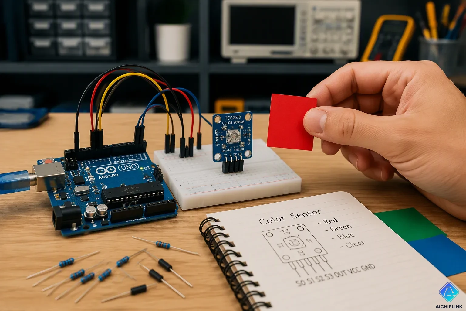
You want to sort colored objects automatically, but your color sensor gives inconsistent readings. You need accurate RGB values, yet you're not sure which sensor to pick or how to calibrate it right. This guide answers those questions directly.
You'll learn about two popular choices: the TCS230 and the ISL29125. Both work with Arduino, but they differ in wiring and accuracy. We'll go through hardware setup, calibration steps, and working code for each sensor.
Color detection doesn't have to be frustrating. With clear steps, you'll get reliable results fast. Let's get your color sorting project moving forward.
Key Takeaways
-
Choose the TCS230 for simple projects and the ISL29125 for precise color work.
-
Calibrate your sensor in the same lighting conditions you will use it in.
-
Place the sensor close to the object to get accurate color readings.
-
Use the TCS3200 with the same code as the TCS230 because they work the same way.
-
Calibrate once per session and reuse the constants to save time.
Color Sensing Principles
How Color Sensors Detect Light
A color sensor uses a light source and a receiver together. The sensor sends out light from a transmitter, then measures the light that bounces back from the object's surface. Inside the receiver, a photodiode array sits under a color filter array, much like the Bayer pattern in digital cameras. Each photodiode has a filter that lets through only red, green, or blue light. This setup allows the sensor to capture separate intensity readings for each wavelength.
The sensor then compares the ratios of these three intensities to figure out the object's color. For example, a red object reflects only red light, while a white object reflects all three colors equally. These unique ratios give you the data you need to identify colors accurately.
Some sensors turn light intensity directly into a frequency signal. The TCS3200, for instance, outputs a frequency that matches the detected light intensity. This method removes the need for an external ADC, because your Arduino can read the frequency signal straight from its digital pins. Other sensors, like the AS7341, have multiple 16-bit ADCs built in to change analog signals into digital data for parallel processing.
Key Specifications
When picking a color sensor for your Arduino project, you need to know a few important specifications. The table below shows the key parameters for the ISL29125:
| Specification | Value |
|---|---|
| Supply Voltage | 3.3V |
| Interface | I2C |
| Sensor Type | Light, Color Sensor |
The ISL29125 runs at 3.3V, so you must connect it to your Arduino's 3.3V output pin, not the 5V pin. Its I2C interface uses only two wires for communication, which makes your wiring setup much simpler.
Modern color sensors also come with built-in amplification circuits. This on-chip transimpedance amplifier changes photocurrent into a voltage output, improving noise immunity and cutting down external interference. The red, green, and blue transmissive filters shape the spectral response to match human eye perception, giving you readings that align with what you see naturally.
The sensitivity of the ISL29125 is not listed in the standard documentation, so you should test it against known color references during calibration. This hands-on method ensures your rgb color readings stay consistent across different lighting conditions.
Understanding these principles helps you choose the right sensor for your specific needs. Whether you want frequency-based output for simple projects or digital I2C communication for precise measurements, knowing how these parts work together makes your Arduino color detection projects more dependable.
Using the TCS230 Color Sensor
Wiring Setup
The TCS230 color sensor adds detection to your projects. This sensor uses an 8x8 photodiode array with 16 red, 16 green, 16 blue, and 16 clear photodiodes. It can detect a wide range of visible colors. The TCS230 operates on a supply voltage of 2.7V to 5.5V, so you can power it directly from the 5V output. It provides a square wave output whose frequency matches the light intensity of the chosen color. This TTL logic-level output simplifies interfacing.
For the wiring, connect the sensor pins to the Arduino Uno as follows:
-
GND to GND
-
VCC to 5V
-
S0 to digital pin 2
-
S1 to digital pin 3
-
S2 to digital pin 4
-
S3 to digital pin 5
-
OUT to digital pin 6
Leave the OE pin unconnected since it is an active low enable pin.
The S0 and S1 pins control the output frequency scaling. This feature lets you adjust the sensor's output to match your microcontroller's capabilities. The sensor offers three scaling ratios:
-
S0 LOW, S1 LOW: Power Down mode
-
S0 LOW, S1 HIGH: 2% scaling
-
S0 HIGH, S1 LOW: 20% scaling
-
S0 HIGH, S1 HIGH: 100% scaling
For most projects, set S0 to HIGH and S1 to LOW for 20% scaling. This reduces the output frequency to a range that the Arduino can read accurately using the pulseIn function.
The S2 and S3 pins select which photodiode type to read. Set S2 LOW and S3 LOW for red, S2 HIGH and S3 HIGH for green, and S2 LOW and S3 HIGH for blue. The sensor includes four built-in white LEDs that illuminate the object, allowing operation in complete darkness. The TCS3200 shares the same pinout and operation.
Calibration and Code
Calibration is the most important step for accurate RGB readings. You need to obtain reference objects for white and black. White craft paper works well for the maximum reading, and black craft paper works for the minimum. Perform readings in a dark room or shade the sensor from ambient light. Place the sensor within a few centimeters to reduce color washout. Allow the sensor to stabilize for a few seconds.
Record the pulse width values for each rgb color channel at both extremes. Store these as redMin, redMax, greenMin, greenMax, blueMin, and blueMax in your code. Then, for each color, read the pulse width and map it to a 0-255 RGB value using the map() function. The formula looks like this: redValue = map(redPW, redMin, redMax, 255, 0). This scales the raw readings so that black maps to 255 and white maps to 0.
Several common issues can affect your readings. The table below shows the problems and their solutions:
| Common Issue | Solution |
|---|---|
| Sensor too far from object causing color washout | Place sensor closer to reduce ambient reflection |
| Short sampling time leads to unreliable readings | Use longer sampling time, ideally 1 second or more |
| Variable overflow in code | Declare variables as uint32_t to avoid overflow |
| Ambient light interference | Shroud sensor to block external light |
| Distant or poor lighting affecting accuracy | Keep sensor within few centimeters and minimize ambient light |
The code reads color values from the TCS230 or TCS3200 using the pulseIn function. Define three functions: getRedPW(), getGreenPW(), and getBluePW(). Each function sets the S2 and S3 pins to select the appropriate photodiode, then calls pulseIn(sensorOut, LOW). In the setup() function, set the pin modes, configure S0 and S1 for 20% scaling, and start Serial communication. In the loop() function, read the pulse width for each color with a 200ms delay, then map the values to 0-255 using your calibration constants. Print the readings to the Serial Monitor. You can perform calibration once and reuse the constants in your final application. This approach saves time and ensures consistent results. The TCS230 and TCS3200 follow the same code structure, making it easy to switch between sensor versions.
Using the ISL29125 Color Sensor
I2C Connection
The ISL29125 uses the I2C protocol, which makes wiring much easier. You only need four wires to connect this color sensor to your Arduino. This sensor works at 3.3V logic, so plug it into the 3.3V pin, not the 5V pin.
Follow these steps to wire the sensor correctly:
-
Connect the sensor's GND pin to your Arduino's GND pin.
-
Connect the sensor's VCC pin to your Arduino's 3.3V output.
-
Connect the sensor's SDA pin to your Arduino's A4 pin, which handles I2C data on the Uno.
-
Connect the sensor's SCL pin to your Arduino's A5 pin, which handles the I2C clock.
Your breakout board probably has 4.7kΩ pull-up resistors on the SDA and SCL lines already. If your board lacks these resistors, add them yourself. Without pull-ups, I2C communication will fail silently. Also, check that your microcontroller's I2C pins run at 3.3V logic levels. If you use a 5V board without level shifting, you could damage the sensor permanently.
The I2C device address defaults to 0x44. You can pass an address parameter to the ISL29125 constructor if your board uses a different address. Most breakout boards stick with the default, so you rarely need to change this setting.
Calibration and Code
The Adafruit_ISL29125 library handles the low-level register setup for you. This library sets the sensor's range and resolution automatically during startup. You just call the library's begin function, then read the red, green, and blue values directly.
Calibration remains essential for accurate rgb readings. The sensor's raw output changes with ambient lighting conditions. You need reference points to normalize your measurements.
Follow this calibration process:
-
White Balance Calibration: Place the sensor over a white surface under your target lighting. Record the raw readings for each channel.
-
Dark Calibration: Cover the sensor completely to block all light. Record these dark values as your baseline.
-
Normalize Values: Scale your raw readings between the dark and white reference points using the map function.
The normalization formula maps your raw reading to a 0-65535 range. If your raw value falls below the dark reference, the result becomes 0. If it exceeds the white reference, the result becomes 65535. This scaling ensures consistent rgb color values regardless of your lighting setup.
Here is the calibration function you can use:
uint16_t calibrateReading(uint16_t raw, uint16_t dark, uint16_t white) {
    if (white <= dark) return 0;
    if (raw <= dark) return 0;
    if (raw >= white) return 65535;
    return map(raw, dark, white, 0, 65535);
}
After calibration, you can read the sensor's values and apply this function to each channel. The library provides methods to read red, green, and blue intensities directly. Print these normalized values to the Serial Monitor at 115200 baud to verify your setup.
The ISL29125 excels in projects where you need consistent rgb color detection. Its I2C interface frees up digital pins for other components. The built-in library reduces coding complexity significantly. For color-critical applications like paint matching or quality control, this sensor delivers the precision you need. Start with a simple white surface test, then move to colored objects once your calibration produces stable readings.
TCS230 vs ISL29125: Comparison
Key Differences
Both color sensors do the same job but in different ways. The TCS230 talks to your Arduino using digital pins. You control the output speed with the S0 and S1 pins. You pick the red, green, or blue channel with the S2 and S3 pins. The sensor sends out a square wave. Your Arduino reads the length of that wave to find the light level. The ISL29125 uses the I2C system. This system needs only two wires for data and clock. You connect SDA to pin A4 and SCL to pin A5. The sensor changes the light into numbers and sends those numbers to your Arduino.
The table below shows the main differences between the two sensors:
| Feature | TCS230 | ISL29125 |
|---|---|---|
| Interface | Digital pins (S0-S3, OUT) | I2C (SDA, SCL) |
| Voltage | 2.7V to 5.5V | 3.3V only |
| Output | Frequency (pulse width) | Direct digital rgb values |
| Precision | Lower, depends on calibration | Higher, with built-in ADC |
| Calibration | Manual, requires reference objects | Library-assisted, simpler process |
| Cost | Lower | Higher |
Precision is a big difference. The TCS230 sends out a frequency signal. You measure this frequency with the pulseIn command. Light from the room and how long you sample affect your readings. You must calibrate carefully to get steady results. The ISL29125 has a built-in converter that changes analog to digital. It gives you direct number values for each color. You get steadier results with less work.
Calibration difficulty also separates these sensors. The TCS230 needs careful calibration. You must record white and black reference numbers for each color channel. Then you change the raw numbers to a 0-255 range. The ISL29125 has a library that sets up the sensor. You still need to calibrate, but it is easier. The library handles the register setup and range choice.
Use Cases
The TCS230 works well for simple projects and prototypes. Its low cost and easy interface make it great for beginners. You can build a color sorting robot with this sensor.
The TCS230 sensor is used in a color detecting and sorting robot. It reads the frequency output to sort objects by color. This prototype uses a microcontroller and servo motors to sort objects automatically in places where manual work is not possible. It shows a typical DIY and industrial use case.
You can build this project with an Arduino, a servo, and a TCS230. The code reads the RGB values. It tells the servo to move objects into the right bins. The TCS3200 module has the same pin layout. You can use the TCS3200 with the same code. The TCS230 color sensor is good for learning and prototyping.
The ISL29125 is good for color-critical jobs. Use it for paint matching, quality control, or any project where accurate RGB values matter. The I2C interface lets you connect many sensors to one Arduino. You get reliable data without struggling with frequency readings. The library support cuts down coding time.
Pick the TCS230 for fast projects and learning. Pick the ISL29125 for precise work. Both sensors give good results when you calibrate them right. Your choice depends on what your project needs and how much you can spend.
Both sensors deliver reliable RGB values through different methods. The TCS230 uses 16 photodiodes per color and outputs a frequency signal. Your Arduino reads this frequency easily. This sensor works well for simple projects like color sorting. The ISL29125 provides 16-bit digital output through I2C. It offers higher precision for color-critical tasks. Calibration remains the most important step for accurate results with either color sensor. You should start with the TCS230 for a quick project. Move to the ISL29125 when you need better resolution. The hands-on experience you gain will help you build better color detection systems. Now pick a sensor, wire it up, and start detecting colors. Share your results in the comments!

Written by Jack Elliott from AIChipLink.
AIChipLink, one of the fastest-growing global independent electronic components distributors in the world, offers millions of products from thousands of manufacturers, and many of our in-stock parts is available to ship same day.
We mainly source and distribute integrated circuit (IC) products of brands such as Broadcom, Microchip, Texas Instruments, Infineon, NXP, Analog Devices, Qualcomm, Intel, etc., which are widely used in communication & network, telecom, industrial control, new energy and automotive electronics.
Empowered by AI, Linked to the Future. Get started on AIChipLink and submit your RFQ online today!
Frequently Asked Questions
Why does my color sensor give different readings in different rooms?
Ambient light changes your sensor's output. The TCS230 and ISL29125 both measure reflected light, so room lighting affects results. You must calibrate each sensor in the environment where you plan to use it. Recalibrate whenever you move to a new lighting condition.
Can I use the TCS3200 with the same code as the TCS230?
Yes. The TCS3200 and TCS230 share the same pinout and operation. You can swap one for the other without changing your wiring or code. Both sensors output frequency signals that your Arduino reads the same way.
How close should I place the sensor to the object?
Place the sensor within a few centimeters of the object. This distance reduces color washout from ambient reflection. Too far away, and the readings become unreliable. Test different distances during calibration to find the sweet spot for your setup.
Do I need to calibrate every time I power up my Arduino?
You should calibrate once per session. Store your calibration constants in the code after you find them. Then reuse those values each time you power up. This approach saves time and keeps your readings consistent across multiple runs.
Which sensor should I choose for my first project?
Start with the TCS230 or TCS3200 for simple projects. They cost less and teach you the basics of frequency reading. Move to the ISL29125 when you need higher precision for color-critical work. Both sensors work well when you calibrate them properly.