Feedthrough Capacitors vs. Regular Capacitors: Key Differences
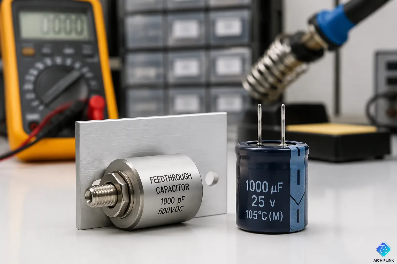
Feedthrough capacitors vs. regular capacitors: the main difference comes down to how many terminals they have. A feedthrough capacitor is a three-terminal capacitor, while a regular capacitor has only two terminals. You mount that third terminal right onto a metal panel or bulkhead. This makes a low-inductance ground path. The design gives these parts a clear edge in high-frequency EMI filtering and noise suppression. A regular capacitor cannot match that performance at high frequencies. Engineers call these three-terminal or feedthrough capacitors for that reason. A feedthrough capacitor also stops high-frequency noise and EMI from escaping a shield. Construction, mounting, performance, and application set these parts apart. That knowledge helps you pick the right component.
Key Takeaways
-
Feedthrough capacitors have three terminals and attach directly to a metal panel. This creates a low-inductance ground path.
-
Regular capacitors have two terminals and use PCB traces to connect to ground. This adds inductance and limits how well they work at high frequencies.
-
Feedthrough capacitors do a much better job of filtering high-frequency noise than regular capacitors. They work well in the MHz to GHz ranges.
-
Use feedthrough capacitors where wires enter a box to cut down EMI. Use regular capacitors for local decoupling and storing energy.
-
Pick the filter type that fits what you need: C, LC, Pi, or T. Each one gives you different roll-off rates to cut down noise.
Feedthrough Capacitors vs. Regular Capacitors: Core Differences
The key difference between feedthrough and regular capacitors starts with their inside design. A regular capacitor has two separate leads, one on each electrode. A feedthrough capacitor has a totally different setup. Inside, a feedthrough capacitor has a center conductor that passes through a cylinder-shaped ceramic body. That conductor forms the signal path. The outside surface is the ground connection. This coaxial design removes most of the self-inductance that holds ordinary parts back.
Feedthrough Capacitor vs Standard Capacitor: Structure
When you compare the structures, you see one clear difference. A standard capacitor is built from stacked dielectric layers with internal electrodes that alternate. You connect to those electrodes through two end terminals. The electrode does not connect directly to ground. It connects to a PCB trace, then a via, and then the ground plane. That path adds parasitic inductance. The feedthrough body works in a different, important way. Its tube-shaped ceramic dielectric has metallization on the inside and outside. A center lead touches the inner surface. The outer metallization is meant to be soldered right onto a metal panel or bulkhead. Current moves along the center lead, and the outer shell acts as the return path. This design makes it easy to compare feedthrough and standard capacitors. One uses a coaxial path, and the other uses two separate leads.
Three-Terminal vs Two-Terminal Design
The number of terminals comes from that design. A feedthrough capacitor has three terminals. Two terminals are just the two ends of the center conductor. The third terminal is the outer shell. You mount that shell directly onto a shielding enclosure. The ground path does not travel through a PCB trace or a via. It goes straight into the metal wall. A two-terminal capacitor always needs those extra connections, and each one adds parasitic inductance. For a standard leaded capacitor, engineers find it hard to get equivalent series inductance below 4 nH. A 220 nF leaded part self-resonates around 5.4 MHz. Above that frequency, filtering stops working. A feedthrough capacitor removes most lead inductance. It shows little sign of ESL effects and keeps high insertion loss beyond 1 GHz. As a feedthrough filter, it works well from the MHz range to the GHz range. A normal two-terminal capacitor usually is not effective above about 100 MHz.
| Electrical specification | Feedthrough capacitor | Regular capacitor |
|---|---|---|
| Parasitic inductance | Very low | Higher |
| High-frequency filtering | Excellent, MHz to GHz | Limited above ~100 MHz |
| Self-resonant behavior | Effective at higher frequencies | Drops above self-resonant frequency |
| Insertion loss | Can exceed 60–80 dB at resonance | Lower attenuation at high frequency |
Because of this low-inductance ground, feedthrough capacitors block electromagnetic interference much better. The direct shield contact reduces radiation and gives noise currents a clean path. That is why engineers pick feedthrough capacitors for enclosure openings and high-frequency EMI filtering. A regular capacitor still works for local decoupling and low-frequency tasks, but it cannot match the high-frequency response. In a sweep from 10 MHz to 1 GHz, a standard MLCC has more residual series inductance and a lower self-resonant frequency. The feedthrough capacitor gives much steeper attenuation. So the practical choice between feedthrough and regular capacitors comes down to this. When shielding and high-frequency EMI matter, the three-terminal component wins.
Feedthrough Capacitor Construction and Mounting
Solder-Type, Resin-Sealed, and Glass Seals
When you shop for a feedthrough capacitor, you will see several sealing styles. Solder-type parts have a metal body that you solder right into a bulkhead. Resin-sealed versions use epoxy to fill the gap, which keeps moisture out and costs less. Glass-sealed feedthrough capacitors melt glass between the center pin and the outer shell. That glass bond creates a hermetic seal and handles extreme temperatures. High-current versions use a thicker center conductor and a bigger ceramic body. The inside build of a feedthrough capacitor changes with each style, but the coaxial ground path stays the same.
Regular capacitors use very different packaging. Through-hole and surface-mount styles lead the market. You solder them onto a PCB pad, and the ground return goes through a trace and a via. That path adds inductance. A feedthrough capacitor avoids this problem because its outer shell touches the chassis wall directly.
Panel Mount vs PCB Mount
Panel mounting gives a feedthrough capacitor its biggest advantage. The threaded body and nut create a 360-degree metal-to-metal contact with the enclosure. A star washer bites through paint or anodize to reach bare metal. This step matters because an insulating coating blocks metal-to-metal contact and raises joint resistance. A gasket pressed on a coated flange leaks at RF, so you must mask bare metal or use a conductive conversion coating. Torque also matters. Under-tightening raises contact resistance, and over-tightening can crack the ceramic.
PCB mounting works well for regular capacitors in local decoupling and energy storage. However, a feedthrough capacitor mounted on a panel isolates its input and output terminals. The metal wall stops high-frequency coupling between them. This isolation, plus the short ground return, keeps filtering effective at UHF and gigahertz frequencies. A press-in fit or a solder-in joint can also work, but each method demands tight process control. A weak solder fillet breaks the high-frequency ground path.
High-Frequency Performance: Low ESL Feedthrough Advantages
A feedthrough capacitor beats regular capacitors at high frequencies for one reason: it has very low equivalent series inductance. With such low ESL, it creates a clean low-pass filter. You get strong high-frequency attenuation without the self-resonance issues that bother ordinary capacitors. Here is why.
Self-Resonance in Regular Capacitors
Every real capacitor has some parasitic inductance. Leads, mounting pads, vias, and PCB traces add inductance in series with it. All this adds up. That total series inductance lowers the capacitor's self-resonant frequency. Above that point, the part acts like an inductor, not a capacitor. So your high-frequency noise filtering stops working.
Footprint size also matters. Smaller footprints raise the self-resonant frequency. Larger pads work like inductors with a bigger cross-sectional area. They add more parasitic inductance and lower the self-resonant frequency. Via count matters as well. Adding more parallel vias between the pads of a footprint cuts ESL and moves the series resonance higher.
Inductive vias and parasitic capacitance can form resonant circuits. A via's self-inductance is small enough that these resonances are in the GHz range. However, inductors added in series lower the resonant frequency.
A better layout can reduce these effects. Lower-inductance footprints and parallel vias both raise the self-resonant frequency. But you cannot remove the lead and trace inductance entirely. That is the limit where a feedthrough capacitor stands out.
Low Grounding Inductance in Feedthrough Capacitors
A feedthrough capacitor fixes the inductance issue at its source. Its outer shell mounts directly to the chassis. That direct contact makes a low-impedance ground path with almost no lead inductance. The coaxial design and the three-terminal structure both cut parasitic inductance compared to a standard two-terminal part, which raises insertion loss in the high-frequency ESL-dominated range.
The measured payoff is large. A three-terminal low-ESL capacitor shows higher insertion loss than a standard two-terminal MLCC at 10 MHz and above. These gains matter for EMI and RFI suppression, where every decibel counts.
That is why a feedthrough filter still works beyond 1 GHz. The low-impedance ground path gives EMI a clean route to the chassis. High-frequency noise suppression becomes dependable instead of barely adequate. For EMI filtering in shielded enclosures, the low-ESL design delivers high-frequency noise suppression that a regular capacitor simply cannot match. If your design must meet strict EMI limits, this difference decides the outcome.
Feedthrough Capacitors Design, Uses, and Best Practices
C, LC, Pi, and T Filter Types
You can pick from four main circuit designs when you choose a feedthrough capacitor. Each type gives a different roll-off rate. A C filter gives you 20 dB per decade. An LC filter doubles that to 40 dB per decade. Pi and T filters reach 60 dB per decade. Higher-order designs give steeper roll-off in the stopband, but they take up more board or chassis space and cost more.
| Filter Topology | Insertion Loss Roll-off Rate |
|---|---|
| C Filter | 20 dB/decade |
| LC Filter | 40 dB/decade |
| Pi/T Filters | 60 dB/decade |
A Pi filter uses two capacitor elements with an inductor between them. This design gives the best high-frequency filtering performance. It shows low impedance to both the source and the load. The C type works only for basic high-frequency filtering. The Pi type works better for demanding EMI suppression and power supply entry filtering. You should pick a feedthrough filter type based on your attenuation needs and your available space.
Where Regular Capacitors Still Work Well
A standard capacitor is still a good choice for local decoupling, energy storage, and lower-frequency filtering. You can use ordinary capacitors on a PCB when your noise problem is below a few hundred MHz. A regular bypass capacitor connects from a signal or power line to ground through PCB traces. That path adds parasitic series inductance. This inductance limits EMI filtering effectiveness above roughly 100 MHz.
A feedthrough capacitor removes that inductance path. It gives steady, wideband high frequency noise filtering up to several GHz. You should use a feedthrough capacitor at enclosure entry or exit points, such as chassis walls or connector bulkheads. Choose one when your high-frequency noise problem happens above a few hundred MHz. You also need one when standard decoupling options have failed. For high frequency noise suppression at a shielded boundary, the three-terminal part wins. For local decoupling and energy storage, a regular capacitor still does the job well.
A feedthrough capacitor gives you a three-terminal, low-inductance path to ground. That design beats regular parts for high-frequency filtering and EMI control. The direct panel mount is the key structural edge over a standard two-terminal capacitor. Regular capacitors still serve local decoupling, energy storage, and lower-frequency work. Yet feedthrough capacitors win when signals cross a shielded boundary. Use them at enclosure entry or exit points for reliable noise suppression. Before you choose between feedthrough capacitors vs. regular capacitors, check your operating frequency, grounding layout, and EMI limits. That review points you to the right part.

Written by Jack Elliott from AIChipLink.
AIChipLink, one of the fastest-growing global independent electronic components distributors in the world, offers millions of products from thousands of manufacturers, and many of our in-stock parts is available to ship same day.
We mainly source and distribute integrated circuit (IC) products of brands such as Broadcom, Microchip, Texas Instruments, Infineon, NXP, Analog Devices, Qualcomm, Intel, etc., which are widely used in communication & network, telecom, industrial control, new energy and automotive electronics.
Empowered by AI, Linked to the Future. Get started on AIChipLink and submit your RFQ online today!
Frequently Asked Questions
What makes a feedthrough capacitor different from a regular capacitor?
A feedthrough capacitor has three terminals, not two. Its outer shell mounts straight onto a metal panel. That direct contact makes a low-inductance ground path. A regular capacitor sends its ground current through PCB traces and vias. Those add parasitic inductance and limit high-frequency performance.
Can I replace a regular capacitor with a feedthrough capacitor on my PCB?
Not always. A feedthrough capacitor needs a metal bulkhead for its ground terminal. You cannot mount it on a standard PCB pad. Use it at enclosure entry points. Keep regular capacitors for local decoupling and energy storage on the board itself.
Why do feedthrough capacitors filter high-frequency noise better?
Their coaxial design removes most lead inductance. The outer shell touches the chassis directly. Noise then has a short, clean path to ground. Regular capacitors self-resonate at lower frequencies because of lead and trace inductance. Above that point, they act like inductors and stop filtering.
Which filter type should I choose for my application?
It depends on how much filtering you need. A C filter gives 20 dB per decade. An LC filter gives 40 dB per decade. Pi and T filters reach 60 dB per decade. Pick a Pi filter for demanding EMI suppression and power supply entry filtering.
When is a regular capacitor still the better choice?
Use a regular capacitor for local decoupling, energy storage, and filtering below a few hundred MHz. It is cheaper and easy to mount on a PCB. Choose a feedthrough capacitor only when signals cross a shielded boundary or your noise problem sits above a few hundred MHz.