What Is a Feedthrough Capacitor and How Does It Work?
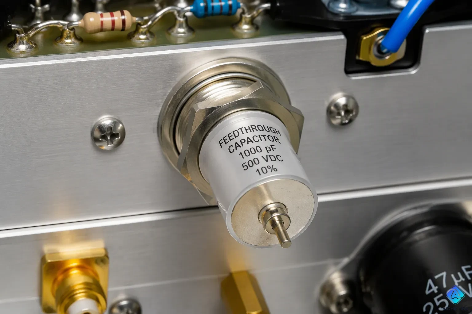
A feedthrough capacitor is a three-terminal capacitor. It filters high-frequency noise while passing DC or low-frequency AC signals. Manufacturers build this component as a ceramic tube with inner and outer metal layers forming two plates. One plate connects to the signal conductor, and the other to ground, creating a grounded barrier. The conductor passes through that barrier. Feedthrough capacitors block unwanted high-frequency interference while letting desired signals travel without disruption. Engineers use feedthrough capacitors in many circuits. This article explains the structure, working principle, types, and purpose of the feedthrough capacitor. Each part builds on the last in a clear, step-by-step way.
Key Takeaways
-
A feedthrough capacitor blocks high-frequency noise but lets DC and low-frequency signals go through.
-
Its ceramic tube and metal layers make a low-impedance path to ground for noise, thanks to a short ground connection.
-
Feedthrough capacitors do a better job than regular capacitors at high frequencies. This is because they have very low inductance.
-
Different types like C, L, Pi, and T give more noise reduction for different circuit needs.
-
Engineers use feedthrough capacitors in medical, satellite, electric vehicle, and aerospace systems to reliably cut down EMI.
Feedthrough Capacitor Definition and Structure
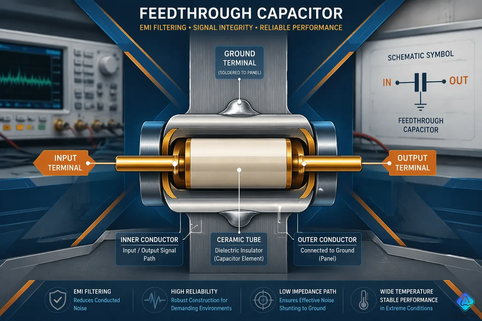
A feedthrough capacitor is a device with three terminals. It has an input, an output, and a ground terminal. The signal goes in one end and comes out the other. The ground terminal connects to a metal barrier. This setup is the basic structure of feedthrough capacitor designs. Engineers use it to filter high-frequency noise in circuits. The feedthrough capacitor definition also shows the importance of the ground terminal.
Ceramic Tube Construction
The main part of a feedthrough capacitor is a ceramic tube. Manufacturers put a metal layer on the inside of this tube. They also put a metal layer on the outside. These two metal layers work as the plates of a capacitor. The ceramic between them works as the dielectric. This build makes a strong and small component. The shape of the tube lets the conductor go straight through the middle. The metal layers stick tightly to the ceramic. This bond makes sure the component works well for a long time.
The value of capacitance depends on the ceramic material and the tube's size. Ceramic feedthrough capacitors for RF and EMI filtering come in many sizes. They range from picofarads to microfarads. This range covers low-capacitance RF filtering and general EMI filtering needs. A ceramic tube feedthrough capacitor usually gives 10 pF to 0.1 µF. It can handle working voltages up to 2500 VDC. A multilayer monolithic discoidal capacitor gives 100 pF to 10 µF. Its working voltage goes up to 400 VDC. These numbers show how flexible the ceramic tube design is. Engineers pick the capacitance value based on the frequency of the noise they need to filter. The choice of ceramic material affects temperature stability and voltage rating.
The Grounded Barrier Concept
The grounded barrier is a key part of this component. The outer metal layer of the ceramic tube connects to a metal panel or box. This panel acts as the ground reference. The signal wire goes through the center of the tube. The tube sits in the wall of the box. This setup makes a barrier between the input and output sides. The barrier keeps the noisy environment away from the clean signal path. The barrier stops noise from moving along the wire.
The wire goes through this barrier without touching it. The ceramic tube insulates the wire from the grounded outer layer. At the same time, the tube gives a capacitive path to ground. This path only works for high-frequency signals. Mounting the outer shell directly to the shield cuts down on ground-path lead inductance. A standard two-terminal capacitor with leads has 1–5 nH of parasitic lead inductance. This inductance can be higher at high MHz–GHz EMI frequencies. The feedthrough design reduces this problem. The shorter ground path makes the component work better at high frequencies. This direct connection gets rid of the long leads that add inductance.
Because it is directly installed on the metal panel, it has lower grounding inductance than a standard three-terminal capacitor. The lead inductance has almost no effect. As a result, the feedthrough capacitor works better than standard capacitors.
This grounded barrier idea explains why feedthrough capacitors work so well. The signal goes through the barrier. Noise finds a short path to ground. The structure of feedthrough capacitor designs makes this possible. The ceramic tube and metal layers form a simple but effective filter. This design gives a reliable solution for many electronic systems.
Working Principle of Feedthrough Capacitor
A feedthrough capacitor works on one simple idea. It sends unwanted high-frequency energy to ground. At the same time, it lets the signal you want keep going. The ceramic tube acts as a capacitor between the signal line and the grounded outer shell. The signal conductor goes straight through the tube. The outer metal layer connects to the chassis or panel ground. This setup makes a low-impedance path to ground for noise. Meanwhile, the main signal travels through the center conductor without stopping. So the working principle of feedthrough capacitor design combines two jobs in one part: sending signals and filtering noise.
Low-Impedance Path to Ground
High-frequency noise acts differently from DC or low-frequency signals. The capacitor shows low impedance to high-frequency energy. That impedance drops as the frequency goes up. The formula for capacitive reactance is Xc = 1 / (2πfC), where f is frequency in hertz and C is capacitance in farads. A higher frequency gives a lower reactance. So the noise current picks the capacitor path over the signal path. It flows through the ceramic dielectric to the grounded outer layer. This is high-frequency signal bypass at work. The noise never makes it to the output side of the barrier.
The grounded barrier idea makes this path very short. The outer shell mounts right onto the metal panel. This direct connection cuts down the inductance in the ground path. A short ground path keeps the impedance low even at very high frequencies. That is why feedthrough capacitors do so well at high-frequency attenuation. The part stays effective where regular capacitors start to fail.
Passing DC and Low-Frequency AC
DC and low-frequency AC signals act in the opposite way. At low frequencies, the capacitive reactance gets very large. The capacitor looks almost like an open circuit to these signals. So the signal you want passes through the center conductor with little loss. It does not go to ground. This picky behavior makes the feedthrough capacitor a natural low-pass filter. It passes what the circuit needs and throws away what it does not.
Regular two-terminal capacitors fall short at high frequencies. Their lead wires add parasitic inductance. Above a certain frequency, the capacitor becomes inductive. It stops blocking noise and may even make it worse. The table below compares the two designs.
| Capacitor type | Behavior above resonance | Suitability for high-frequency line-to-earth suppression | Comparison result |
|---|---|---|---|
| Two-terminal capacitor | Acts like an inductor due to lead-wire inductance; impedance becomes Z = 2πfL | Not suitable when suppression is needed above resonance | Lower effective SRF |
| Feedthrough capacitor | Performance remains close to ideal, aside from minor element-dimension resonances | Required for suppression above the resonant frequency | Higher effective SRF |
A 1 μF feedthrough capacitor and a 1 μF two-terminal capacitor show this gap. The feedthrough type gives strong filtering performance that the two-terminal capacitor cannot match. The feedthrough capacitor has a higher effective self-resonant frequency because its shunt-path inductance is lower. It stays capacitive and keeps attenuating at frequencies where a regular two-terminal capacitor has already become inductive. A three-terminal capacitor can be built with very small ESL while keeping ESR low. This greatly improves its frequency characteristic compared with a two-terminal capacitor of the same capacitance value. The better frequency characteristic means a higher self-resonant frequency due to the reduced ESL.
Purpose of a Feedthrough Capacitor and Its Types
A feedthrough capacitor has one main job: it blocks EMI but still lets signals pass. The main reasons to use it are to stop high-frequency noise and to let the wanted signals through. Different circuits need different filter designs. Knowing the types helps engineers pick the right one. This section explains how feedthrough capacitors are sorted by circuit setup.
C-Type and L-Type Configurations
A C-type setup uses just one shunt capacitor. This simple design cuts noise at a rate of 20 dB per decade. In a 50-ohm system, it gives 10 dB of loss at 10 kHz and 30 dB at 100 kHz. It works best for circuits with high impedance sources and loads. The structure is simple—just one capacitor.
Full Load Insertion Loss per MIL-STD-220 (50 ohms): 150 kHz: 16 dB 300 kHz: 38 dB 1 MHz: 75 dB 10 MHz: 80 dB 100 MHz: 80 dB
The C-type feedthrough capacitor works for standard EMI filtering. It gives wide noise reduction and is low cost. Uses include telecom gear, signal lines, and industrial computers. It is a general-purpose filter for basic high-frequency needs.
An L-type setup adds a series inductor to the shunt capacitor. This gives a steeper noise cut of 40 dB per decade. A typical L-type filter gives 20 dB at 100 kHz and 60 dB at 1 MHz. The inductor stops high-frequency noise before it reaches the capacitor. Then the capacitor sends the leftover noise to ground. The L-type uses more parts and costs more. But it filters much better. Engineers use L-type filters when a C-type alone is not strong enough.
Pi-Type and T-Type Configurations
A Pi-type setup uses two shunt capacitors with a series inductor between them. This gives a noise cut of 60 dB per decade. In a 50-ohm system, a Pi-type filter gives about 20 dB at 15 kHz and 80 dB at 150 kHz.
Theoretical MIL-STD-220 insertion loss for a Pi filter: 150 kHz: 33 dB 300 kHz: 51 dB 1 MHz: 83 dB 10 MHz: >100 dB 100 MHz: >100 dB
Engineers pick Pi-type feedthrough capacitors for tough environments. They work better at high frequencies than simpler designs. The extra parts raise the cost. But the steep noise cut removes noise that simpler filters cannot.
A T-type setup uses two series inductors with a shunt capacitor between them. This design also gives a 60 dB per decade noise cut. Its performance matches the Pi-type in slope and loss. The T-type feedthrough capacitor handles high impedance sources and loads in a different way. Engineers choose between Pi and T based on circuit impedance. Sorting feedthrough capacitors into these types helps match the filter to the job. Each setup has strengths for different noise issues.
Key Features and Applications of Feedthrough Capacitors
Advantages Over Standard Capacitors
Feedthrough capacitors have special features that make them better than normal two-terminal parts. Their low unwanted inductance keeps resistance low at very high frequencies. A regular capacitor's lead wires add inductance that hurts performance. Feedthrough capacitors keep their self-inductance very low because the ground path is short and direct.
Feedthrough capacitors (tubular ceramic) usually have lower ESL than two-terminal capacitors of the same value. This leads to a higher SRF and extends the range where they work as good shunt parts.
This higher self-resonant frequency means the part keeps filtering where other capacitors stop working. The low-inductance design also gives lower grounding inductance than standard three-terminal capacitors. Engineers get reliable high-frequency filtering without hard tuning.
Feedthrough capacitors and bypass capacitors also differ in how they handle current. The feedthrough type is mostly free from through-current effects. It shows only small and predictable changes when voltage is applied. Ferrite beads, on the other hand, lose a lot of inductance at full current because of saturation. A ferrite bead may measure 160 nH with a 0.4mm gap at full load. This saturation limits how well they work on high-current lines.
| Parameter | Feedthrough Filter | Ferrite Bead |
|---|---|---|
| Effective Range | 1 kHz – 40 GHz | 10 MHz – 1 GHz |
| Unit Cost | $8–$200 | $0.1–$2 |
| Design Complexity | Low (single component) | Moderate (requires PCB tuning) |
| Lifetime Reliability | >100,000 hours @ 125°C | 50,000 hours @ 85°C |
| Typical Use Case | Satellite comms, MRI machines | Consumer electronics |
Real-World Uses in EMI Suppression
Engineers depend on feedthrough capacitors for electromagnetic interference suppression in tough environments. These parts handle electromagnetic interference across a wide spectrum. Key performance metrics guide their choice for specific jobs.
-
Attenuation Bandwidth (e.g., 10 MHz–40 GHz for 5G base station)
-
Insertion Loss (e.g., >50 dB @ 1 GHz for MIL-STD-461G compliance)
-
Resonant Peaks (<3 dB variation across operating range)
-
Continuous Current (e.g., 10A for EV charging ports)
-
Surge Current (100A/1ms for industrial motor drives)
-
Power Dissipation (<1W thermal loss @ 25°C ambient)
Medical imaging equipment uses these parts for emi/rfi filtering on sensitive signal lines. Satellite communications depend on them for filtering and shielding against cosmic noise. Electric vehicle charging ports need emi filtering that handles high continuous current. Industrial motor drives require surge current protection that ordinary capacitors cannot provide. Aerospace systems use them for high-frequency filtering where reliability matters most. The low-inductance design supports emi suppression in compact spaces. These applications show why feedthrough capacitors remain essential for electromagnetic interference control in modern electronics.
A feedthrough capacitor filters high-frequency noise by sending it to ground through a conductive barrier. The ceramic tube and metal layers make a low-impedance path for unwanted signals. At the same time, DC and low-frequency AC pass through the center conductor without disruption. This design gives engineers a reliable tool for electromagnetic interference suppression.
Feedthrough capacitors work better than ordinary two-terminal capacitors in high-frequency applications. Their low inductance keeps filtering effective where standard parts fail. As electronic devices grow faster and more compact, high-frequency noise control remains critical. Engineers will continue to rely on these components for clean, dependable signal integrity in modern circuit design.

Written by Jack Elliott from AIChipLink.
AIChipLink, one of the fastest-growing global independent electronic components distributors in the world, offers millions of products from thousands of manufacturers, and many of our in-stock parts is available to ship same day.
We mainly source and distribute integrated circuit (IC) products of brands such as Broadcom, Microchip, Texas Instruments, Infineon, NXP, Analog Devices, Qualcomm, Intel, etc., which are widely used in communication & network, telecom, industrial control, new energy and automotive electronics.
Empowered by AI, Linked to the Future. Get started on AIChipLink and submit your RFQ online today!
Frequently Asked Questions
What does a feedthrough capacitor do?
It filters high-frequency noise and lets DC or low-frequency AC signals go through. The ceramic tube makes a capacitive path from the signal line to the grounded outer shell. Noise goes to ground through that path. The signal you want keeps going through the center conductor without any problem.
How does a feedthrough capacitor differ from a regular two-terminal capacitor?
A regular capacitor's lead wires add parasitic inductance, so the part turns inductive above its resonant frequency. A feedthrough capacitor mounts its outer shell right onto a metal panel. That short ground path lowers inductance and raises the self-resonant frequency, so filtering still works at much higher frequencies.
Which capacitance values and voltages do feedthrough capacitors offer?
Ceramic tube types usually go from 10 pF to 0.1 µF with working voltages up to 2500 VDC. Multilayer monolithic discoidal types reach 100 pF to 10 µF with working voltages up to 400 VDC. Engineers pick the value based on the noise frequency they need to filter.
What is the difference between C-type, L-type, Pi-type, and T-type feedthrough capacitors?
A C-type uses one shunt capacitor and cuts noise at 20 dB per decade. An L-type adds a series inductor for 40 dB per decade. Pi-type and T-type designs combine two reactive elements with a shunt capacitor and reach 60 dB per decade. Tougher environments need the steeper filters.
Where do engineers use feedthrough capacitors?
They show up in medical imaging equipment, satellite communications, electric vehicle charging ports, industrial motor drives, and aerospace systems. These applications need reliable electromagnetic interference suppression across a wide frequency range. The low-inductance design also fits compact spaces where standard capacitors struggle.