Why Does Current Lose Voltage Across a Resistor? (And Why "Lose" Is the Wrong Word)
A beginner measures a 9V battery connected to a single 1 kΩ resistor. The voltmeter reads 9V across the resistor. Then they connect two 1 kΩ resistors in series and measure again — 4.5V across each one. "The first resistor ate half my voltage," they say. "The current must be weaker after passing through it."
They measure the current before the first resistor: 4.5 mA. They measure the current after the first resistor, between the two: 4.5 mA. The same. Not weaker. Not reduced. Identical.
This moment of confusion — voltage changed, current did not — is where most circuit fundamentals go wrong for learners, and the confusion persists for years if the underlying reason is never made clear. The short answer is that the question itself contains a misconception: current does not lose voltage. Voltage is not a property of current that gets depleted. Voltage is a difference in electrical potential between two points in the circuit, and a resistor creates a specific, calculable difference in that potential. The current — the flow of charge — passes through completely, carrying the same amount of charge per second as it carried before. What the resistor does is convert some of the energy carried by those moving charges into heat. The charges arrive at the other side of the resistor carrying less energy per charge (lower voltage), but the same number of charges are arriving per second (same current).
Understanding this distinction precisely — energy per charge versus charge per second — is the foundation of every useful circuit calculation.
1.0 The Two Things That Are Not the Same: Voltage and Current
Before explaining what happens in a resistor, the distinction between voltage and current needs to be clear, because the confusion between them is what makes the question feel puzzling.
Current is the flow of electric charge — specifically, the number of electrons (or other charge carriers) passing a given point per second. It is measured in amperes (A), where 1 ampere = 1 coulomb of charge per second = approximately 6.24 × 10¹⁸ electrons per second. Current is a rate of flow, like liters per second in a pipe.
Voltage is the difference in electrical potential energy between two points. More precisely, it is the energy per unit charge — how much energy each coulomb of charge has available to do work. It is measured in volts (V), where 1 volt = 1 joule per coulomb. Voltage is like pressure in a pipe, or height difference in a gravitational system — it is a property of position in the circuit, not of the current itself.
The critical consequence of this distinction: current is the same everywhere in a series circuit. There is no place for charge to accumulate or disappear — every electron that enters a wire segment must also leave it. Voltage, on the other hand, can and does differ between different points in a circuit. The voltage at point A can be higher than at point B, and the difference — the voltage drop — is what drives the current through whatever component connects A to B.
2.0 What Actually Happens Inside a Resistor
At the atomic level, a resistor is a material through which free electrons can move, but not freely. The atoms in the resistor's material are arranged in a lattice structure, and as electrons move through this lattice under the influence of the electric field (the voltage difference), they constantly collide with the lattice atoms.
The collision process:
Each collision transfers some kinetic energy from the moving electron to the lattice atom. The atom vibrates more — which is heat. The electron slows down momentarily, then is accelerated again by the electric field, gains speed, collides again, and so on. This is electrical resistance at the microscopic level: a continuous cycle of acceleration, collision, energy transfer, and re-acceleration.
The result of this process is twofold:
- The material heats up — the transferred energy appears as thermal energy (heat). This is exactly where the "lost voltage" energy goes.
- The electrons arrive at the output end of the resistor with less energy per electron than they had at the input end. Since voltage is defined as energy per unit charge, less energy per electron means lower voltage on the output side.
What does NOT change is the number of electrons passing through per second. The electric field pushes electrons in from one end at exactly the rate they exit the other end — conservation of charge requires this. The current (charge per second) is preserved; only the energy per charge (voltage) decreases.
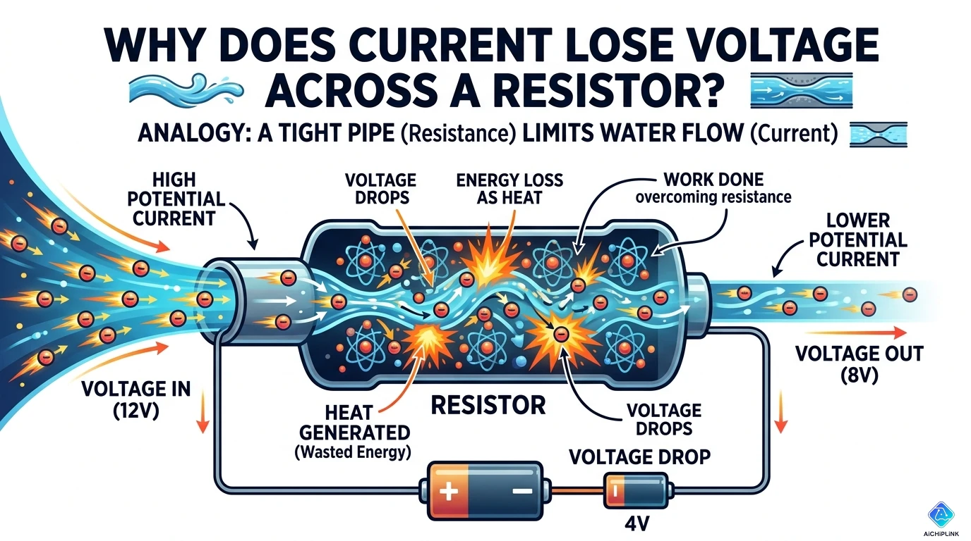
The water analogy — and where it breaks down:
The common analogy is a pipe with a narrow section: voltage = water pressure, current = flow rate (liters/second), resistance = narrowness of the pipe. The pressure drops across the narrow section, but the flow rate (liters per second) is the same before and after.
This analogy is helpful for building the right intuition, but it breaks down in one important way: in the water pipe, a narrow section simply restricts flow and the "lost" pressure is recovered when the pipe widens again. In an electrical resistor, the energy is genuinely converted to heat and cannot be recovered. The voltage drop is a permanent energy conversion, not a temporary restriction.
3.0 The Math: Ohm's Law and Why It Works
Ohm's Law states: V = I × R
Where:
- V = voltage across the resistor (volts)
- I = current through the resistor (amperes)
- R = resistance (ohms, Ω)
This relationship is not an arbitrary definition — it emerges from the physics of electron collisions described in Section 2. More resistance means more collisions per unit length of material, which means more energy converted to heat per unit charge, which means a larger voltage drop for the same current. Ohm's Law captures this proportionality.
Working through the example from the opening:
Circuit: 9V battery, two 1 kΩ resistors in series. Total resistance = 1 kΩ + 1 kΩ = 2 kΩ
Current (same everywhere in the series circuit): I = V / R = 9V / 2,000 Ω = 0.0045 A = 4.5 mA
Voltage across resistor 1: V₁ = I × R₁ = 0.0045 A × 1,000 Ω = 4.5V
Voltage across resistor 2: V₂ = I × R₂ = 0.0045 A × 1,000 Ω = 4.5V
Check (Kirchhoff's Voltage Law): V₁ + V₂ = 4.5V + 4.5V = 9V ✓ — The sum of voltage drops equals the supply voltage. No energy is created or lost; it is all accounted for.
Power dissipated in each resistor:
Power = V × I = I² × R = V²/R
P₁ = 4.5V × 0.0045 A = 20.25 mW (heat generated in resistor 1) P₂ = 4.5V × 0.0045 A = 20.25 mW (heat generated in resistor 2) Total power from battery = 9V × 0.0045 A = 40.5 mW ✓
Every milliwatt delivered by the battery is accounted for as heat in the two resistors. This is energy conservation in a resistive circuit.
What changes when the resistors are unequal:
If R₁ = 1 kΩ and R₂ = 3 kΩ (total 4 kΩ): I = 9V / 4,000 Ω = 2.25 mA (same everywhere in the circuit) V₁ = 2.25 mA × 1 kΩ = 2.25V V₂ = 2.25 mA × 3 kΩ = 6.75V
The larger resistor gets a proportionally larger share of the total voltage. This is the voltage divider principle: voltage distributes in proportion to resistance; current does not divide at all in a series circuit.
4.0 Seeing It in a Real Circuit: Series and Parallel Resistors
Series circuit — voltage divides, current stays the same:
In a series circuit, every component shares the same current. The voltage distributes across each component in proportion to its resistance. This is why resistors in series act as a voltage divider.
Practical application: a 5V sensor output needs to connect to a 3.3V microcontroller input. Two resistors (10 kΩ and 20 kΩ) in series form a voltage divider: the output voltage taken between the two resistors is 5V × 20/(10+20) = 3.33V — exactly what the MCU needs. The current in the divider is 5V / 30 kΩ = 167 µA — small enough to not load the sensor.
Parallel circuit — current divides, voltage stays the same:
In a parallel circuit, every component shares the same voltage across it. The current distributes across each branch in inverse proportion to resistance (more current through lower resistance). This is the complementary behavior: series → voltage divides; parallel → current divides.
The LED resistor example:
A red LED requires approximately 2.0V and 20 mA to operate correctly. Powered from 5V, the resistor in series must handle the remaining voltage: V_R = 5V − 2.0V = 3.0V at I = 20 mA. By Ohm's Law: R = V/I = 3.0V / 0.020 A = 150 Ω. The resistor does not "slow down" the current to protect the LED — it establishes the correct current by converting the excess voltage (3.0V) to heat, maintaining 20 mA through the LED.
5.0 The Energy Question: Where Does the Voltage "Go"?
This is the question the microscopic picture answers most directly.
The energy that corresponds to the voltage drop across a resistor is converted to thermal energy (heat). The resistor's temperature rises above ambient and dissipates this heat into the surrounding air (or through its thermal connection to a PCB or heatsink).
The energy chain:
Battery chemical energy → electrical potential energy (voltage) → kinetic energy of electrons → thermal energy (heat in resistor) via collisions → radiated/conducted to environment
At no point in this chain is energy destroyed. At every point it is conserved and converted from one form to another. "Voltage drop" is the observable signature of this energy conversion: as charge moves through the resistor, each coulomb of charge has less potential energy on the exit side than the entry side, and the difference appears as heat.
Why this matters for circuit design:
The power dissipated in a resistor (P = I² × R, or P = V²/R, or P = V × I — all equivalent by Ohm's Law) determines:
- How hot the resistor will get
- What power rating the resistor requires (a 0.25W resistor in a 1W dissipation application will overheat and fail)
- In battery-powered systems, how quickly the battery is drained
Every resistor in a real circuit is converting some electrical energy to heat. In most low-power circuits this is negligible. In high-current paths (motor drives, power regulators, LED drivers), resistor power dissipation is a primary design constraint.
6.0 ⚠️ Five Misconceptions That Follow From This Confusion
Misconception 1: "Current is weaker after passing through a resistor"
Current (charge per second) is identical on both sides of a resistor in a series circuit. This is required by conservation of charge — electrons cannot accumulate in the resistor. What decreases is the voltage (energy per charge), not the current. Measuring the same current before and after a resistor is the simplest experimental demonstration of this fact.
Misconception 2: "A larger resistor blocks more current, so it protects components more"
A larger series resistor reduces current throughout the entire series circuit (I = V_total / R_total). It does not "protect" the component after it by selectively blocking current — it reduces current everywhere. This matters for LED driver circuits: the series resistor determines current, not a maximum current the LED might draw independently. Without the resistor, the LED has very low resistance and would draw a very high current, overheating instantly.
Misconception 3: "Voltage is used up by the first component in a circuit"
Voltage is a difference in potential between two points — it is not a quantity that one component "uses" and then there is none left for the next one. Each component in a series circuit has a voltage drop proportional to its resistance (Kirchhoff's Voltage Law), and these drops sum to the supply voltage. Even after passing through multiple resistors, the current reaching the last component in the chain is identical to the current leaving the source — only the voltage at that point in the circuit is lower.
Misconception 4: "In a parallel circuit, adding another resistor reduces the voltage across existing resistors"
Adding a resistor in parallel with an existing component (connected directly across the same two nodes) does not change the voltage across either component — it adds another current path, increasing total current from the source but leaving the voltage across both branches identical. This is why parallel combinations of components all operate at the same voltage: they share the same two nodes.
Misconception 5: "Ohm's Law means all components have fixed voltage-to-current ratios"
Ohm's Law (V = IR) applies to ohmic materials — metals and most resistors over a reasonable temperature range. It does not apply to diodes (which have exponential V-I characteristics), capacitors (which do not conduct DC at all), inductors (which have frequency-dependent impedance), LEDs, transistors, or most semiconductor devices. These are non-ohmic components. A diode does not follow V = IR: its current rises exponentially with voltage above its forward threshold. Applying Ohm's Law to predict diode behavior gives wrong answers.
7.0 Real Questions About Voltage Drop
Q: If voltage drops across a resistor but current stays the same, where does the "extra voltage" go in a circuit with a battery, one resistor, and one LED?
A: The total supply voltage is shared between every component in the series circuit. The battery provides, say, 3V. The LED requires approximately 2V to forward bias and pass current (the LED's forward voltage). The remaining 1V must be dropped somewhere — and if a resistor is in series, that resistor takes the remaining 1V. There is no "leftover" voltage: V_battery = V_LED + V_resistor (Kirchhoff's Voltage Law). If the resistor is sized correctly (R = V_R / I), the current through the circuit is exactly what the LED needs. If the LED were connected directly to the battery without a resistor, the battery would force the current upward until the LED's internal resistance and the battery's internal resistance limited it — likely destroying the LED from excess current and heat.
Q: My multimeter shows 5V at one point in my circuit and 3.3V at another point just after a resistor. Does that mean 1.7V "disappeared"?
A: The 1.7V did not disappear — it was converted to heat in the resistor. The voltage difference of 1.7V across the resistor, multiplied by the current through it, gives the power being dissipated as heat: P = 1.7V × I. If the current is 10 mA, for example, P = 1.7 × 0.010 = 17 mW of heat. The total energy leaving the power supply exactly equals the sum of energy converted in each component, including that heat. Energy is conserved; voltage is not preserved — it is converted.
Q: I understand that current stays the same in a series circuit. But I've heard that "adding resistance reduces current." Isn't that a contradiction?
A: Not a contradiction — two different scenarios. "Current stays the same everywhere in a series circuit" means that at any single moment, with a fixed total resistance, the current is identical at every point around the loop. "Adding resistance reduces current" means that if you increase the total resistance in the circuit (by adding more series resistance), the current everywhere in that circuit decreases (I = V/R_total). After you add the extra resistor and the circuit reaches steady state, the current is again identical everywhere — just at a lower value than before. Both statements are correct for their respective situations.
8.0 Quick Reference Card
The Core Distinction — Memorize This:
| Quantity | In a series circuit |
|---|---|
| Current (A) | Identical everywhere — same before and after every component |
| Voltage (V) | Drops across each component — proportional to resistance |
Ohm's Law — Three Equivalent Forms:
| Find | Formula | Use when you know |
|---|---|---|
| Voltage drop | V = I × R | Current and resistance |
| Current | I = V / R | Voltage and resistance |
| Resistance | R = V / I | Voltage and current |
Power Dissipation — Three Equivalent Forms:
| Formula | Use when you know |
|---|---|
| P = V × I | Voltage drop and current |
| P = I² × R | Current and resistance |
| P = V² / R | Voltage drop and resistance |
What a Resistor Actually Does:
- Creates a voltage drop proportional to current (V = IR)
- Converts electrical energy to heat (P = I²R watts)
- Does NOT reduce current flow — current is the same entering and exiting
Kirchhoff's Voltage Law (for any series loop): Sum of all voltage drops = Supply voltage V₁ + V₂ + V₃ + ... = V_supply
The Voltage Divider (two resistors in series): V_out = V_in × R₂ / (R₁ + R₂) (V_out measured across R₂, R₁ connected between V_in and V_out)

Written by Jack Elliott from AIChipLink.
AIChipLink, one of the fastest-growing global independent electronic components distributors in the world, offers millions of products from thousands of manufacturers, and many of our in-stock parts is available to ship same day.
We mainly source and distribute integrated circuit (IC) products of brands such as Broadcom, Microchip, Texas Instruments, Infineon, NXP, Analog Devices, Qualcomm, Intel, etc., which are widely used in communication & network, telecom, industrial control, new energy and automotive electronics.
Empowered by AI, Linked to the Future. Get started on AIChipLink and submit your RFQ online today!
Frequently Asked Questions
Why does voltage drop across a resistor while current stays the same?
Voltage drops because a resistor converts electrical energy into heat as electrons collide with atoms inside the material. Current is the flow of charge per second, and in a series circuit that flow remains the same everywhere because charge cannot disappear. What changes is the energy carried by each charge, not the number of charges moving.
Does current become weaker after passing through a resistor?
No, in a series circuit the current before and after a resistor is identical. The resistor does not “use up” current—it creates a voltage difference across itself. The same electrons continue moving through the circuit, but with less energy per charge after passing through the resistor.
Where does the lost voltage actually go?
The “lost” voltage is really converted into heat. A resistor changes electrical potential energy into thermal energy through electron collisions inside the material. This is why resistors can become warm, especially in high-current circuits where power dissipation is higher.
Why does voltage divide in series but current divides in parallel?
In a series circuit there is only one path, so the same current must flow through every component, while voltage is shared based on resistance values. In a parallel circuit all branches connect across the same two points, so voltage remains the same across each branch, but current splits depending on branch resistance.
How do I calculate voltage drop across a resistor?
Use Ohm’s Law: V = I × R. Multiply the current through the resistor by its resistance value to find the voltage drop. For example, if 10 mA flows through a 220Ω resistor, the voltage drop is 0.01 × 220 = 2.2V.