Testing a 5 pin relay with a 9 volt battery is easy for most car uses. Anyone working with a 5 pin relay or a 5 pin car relay needs a 9V battery, jumper wires, and a multimeter. First, find the relay coil pins. Then, connect the battery and listen for a click. Checking if power flows across the switched pins helps show if it works. Knowing the relay coil resistance is important for good results.
Beginners often make mistakes like wiring the 5 pin relay wrong, using a 9V battery that does not have enough power for car relays, or forgetting to use protective diodes.
Safety is always most important. Beginners should look at datasheets for their 5 pin car relay to stop damage and make sure they test it right.
Key Takeaways
-
Use a 9V battery, a multimeter, and jumper wires to test a 5 pin relay. This helps you check the coil and if it switches right.
-
Find pins 85 and 86. These are the coil terminals. Use a multimeter to measure the coil resistance. Power the coil and listen for a click sound.
-
Check if there is a connection between common, normally open, and normally closed pins. This shows if the relay switches as it should.
-
Always follow safety rules. Do not use water, strong magnets, or broken tools. Look at the relay datasheet before you start testing.
-
Do not make common mistakes. Do not mix up the pins. Do not use weak batteries. Do not skip regular relay checks. This helps stop damage and keeps the relay working well.
Tools and Safety
What You Need
Before you start, gather some simple tools. These tools help you check if the relay works and how much power it uses.
-
9V battery: Gives the right voltage to turn on the relay coil and check power use.
-
Multimeter: Checks if electricity flows, measures resistance, and shows power use at the relay pins.
-
Jumper wires or alligator clips: Help you connect the battery and multimeter to the relay pins safely.
-
5 pin relay: This is the part you are testing. It is often used in cars to control power and current.
A multimeter helps you see if the relay coil uses the right amount of current. It also lets you measure power use when the relay is working. Jumper wires make it easy to hook up the battery to the relay coil pins. This helps you test if the relay switches on and off. The 9V battery gives enough voltage for most small relays. But always check the relay’s datasheet to see the best power use and current numbers.
Tip: Always use tools that are not broken. Bad wires or a broken multimeter can give wrong numbers for current or power use.
Safety Tips
Handle and store relays the right way to keep them safe and get good power use numbers. Do not let the relay touch water, chemicals, or bad gases. These things can cause rust and mess up how current flows. Keep relays out of sunlight and store them at a steady room temperature and humidity. This stops rust and water drops, which can change power use.
Do not drop relays or shake them hard. This can bend parts inside and change how much current the relay uses. Always turn off the power before you wire or change a relay. This keeps you safe from shocks and stops wrong power use numbers. Stay away from strong magnets, too. They can make the relay stop working right and change current and power use.
Note: Check relays before you use them, especially if they sat for a long time. Changes inside the relay can make power use jump around or make switching not work right.
If you follow these safety tips and use the right tools, you can test a 5 pin relay’s power use and current draw without worry.
Identify 5 Pin Relay
Pin Layout
A 5 pin relay is a common part in many automotive systems. Most 5 - pin automotive relays follow the Bosch style, also called TYPE B. This layout makes it easy to spot each pin and connect the relay the right way. The 5 pin relay has a standard pinout used in most automotive applications. The pin layout helps users avoid wiring mistakes and keeps the relay working well.
-
Pin 85 and pin 86 are the relay coil terminals. These sit opposite each other.
-
Pin 30 is the common terminal. It sits below pins 87 and 87a.
-
Pin 87 is the normally open contact. Pin 87a is the normally closed contact.
-
Pin 30 connects to 87a when the relay is off. When the relay coil gets power, pin 30 switches to 87.
-
TYPE B relays are the most common in U.S. vehicles and aftermarket automotive applications.
-
TYPE A relays swap pins 30 and 86. Some European cars use TYPE A, so users must check before swapping relays.
Tip: Never swap TYPE A and TYPE B relays. The pin differences can cause wiring errors or damage.
Most 5 - pin automotive relays are SPDT (Single Pole Double Throw). This type lets the relay switch between two circuits. These relays work well in automotive applications because they handle many loads and can control different systems.
Coil Pins (85 and 86)
The relay coil sits between pins 85 and 86. These pins control when the relay switches. Pin 85 usually connects to ground, and pin 86 connects to switched power in automotive wiring. To check the relay coil, a user can use a multimeter.
-
Set the multimeter to measure resistance (ohms).
-
Touch the leads to pins 85 and 86.
-
A good relay coil shows a resistance between 50 and 120 ohms, often near 75 ohms.
-
If the reading is much higher or shows "OL," the relay coil is bad.
-
For more testing, connect a 9V battery to pins 85 and 86. Listen for a click. This sound means the relay coil works and the relay switches.
The correct identification of pins 85 and 86 is key for safe and accurate testing. Most 5 - pin automotive relays use this layout, making it easy to test and replace them in automotive applications.
Measure Relay Coil
Use a Multimeter
When you use a multimeter to test the relay coil, you can see if it works well and how much power it uses. A digital multimeter lets you check the relay coil resistance and find early problems. Here are the steps to measure relay resistance:
-
Take the relay out of the circuit. This stops other parts from messing up your test and helps you get the right numbers.
-
Turn off all power and let any stored energy out of the parts. This keeps you safe and makes sure your test is correct.
-
Put the multimeter on resistance mode, which is called Ohms. Most digital multimeters can pick the right range by themselves.
-
Put the black lead in the COM spot and the red lead in the VΩ spot.
-
Touch the leads to the relay coil pins, which are usually pins 85 and 86. Make sure the leads touch well so you get a good reading.
-
Look at the number on the multimeter screen. Write this number down so you can check it later.
-
Check if your number matches the relay coil resistance in the datasheet. If it matches, the relay coil is good. If the number is very low, the coil might be shorted. If it is very high or says "OL," the coil might be broken.
Tip: Always turn off the multimeter when you finish so the battery lasts longer.
This way, you can find problems like a broken coil or one that is burned out. If the relay coil gets too hot or the resistance number is not right, the coil may be damaged. You should also test relays when they are working in real life to make sure they use the right amount of power and current.
Coil Resistance Specs
Most 5 pin relays in cars that use 12V have a coil resistance between 50 and 200 ohms. For example, if a relay has a 100-ohm coil and uses 12V, it will use about 120mA of current. This comes from Ohm’s Law, which says current is voltage divided by resistance. The coil resistance changes how much power and current the relay uses. If the resistance is low, the relay uses more current and power. If the resistance is high, it uses less current and power.
| Coil Resistance (Ohms) | Voltage (V) | Current (mA) | Power Consumption (W) |
|---|---|---|---|
| 50 | 12 | 240 | 2.88 |
| 100 | 12 | 120 | 1.44 |
| 200 | 12 | 60 | 0.72 |
Relay makers put coil resistance numbers in datasheets. You should always look at these numbers before you test. If your test number does not match the datasheet, the relay coil might be bad. The coil can go bad from too much voltage, switching on and off a lot, or being in a rough place. Signs of a bad coil are too much heat, a broken coil, or a burnt smell. Testing the relay coil often helps stop problems and keeps power use steady.
Note: It is a good idea to check relay coil resistance and power use every month. These checks help you find problems early and keep car systems working well.
A good relay coil lets current flow right and keeps power use steady. If you follow these steps, you can test relay coil resistance and keep your relay working safely and well.
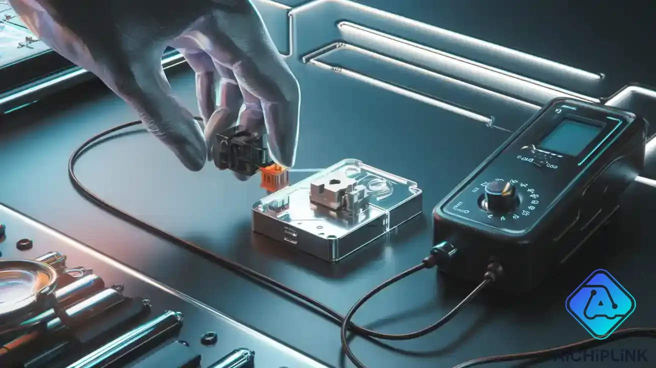
Test with 9V Battery
Connect to Coil Pins
Testing a 5 pin relay with a 9V battery helps users check if the relay coil works. The process starts with finding the correct pins. Most 5 pin relays use pins 85 and 86 for the coil. These pins sit opposite each other on the relay body. Users should always check the relay diagram or datasheet to confirm the pin numbers.
Follow these steps to connect the 9V battery to the relay coil:
-
Identify pins 85 and 86 as the coil terminals on the relay.
-
Attach pin 85 to the ground side of the battery.
-
Connect pin 86 to the positive terminal of the 9V battery.
-
Make sure the battery voltage matches the relay coil rating. Most automotive relays use 12V, but a 9V battery can still activate many relays for testing.
-
If the relay has a built-in diode, match the polarity. Otherwise, polarity does not matter.
-
Double-check pin numbers before connecting wires to avoid mistakes.
Tip: Use jumper wires with alligator clips for a safe and secure connection. This setup prevents accidental shorts and keeps hands away from the relay during testing.
The relay coil receives power when the battery connects to pins 85 and 86. This action energizes the coil and prepares the relay for switching. Users should avoid touching the relay terminals while the battery is connected.
Listen for Click
After connecting the 9V battery to the relay coil, users should listen closely. A working relay makes a clear clicking sound. This click means the coil has pulled the relay contacts into position. The sound comes from the internal switch moving between the normally closed and normally open contacts.
If the relay does not click, users should check the battery and connections. A weak battery may not provide enough power for the coil. Incorrect pin identification can also prevent the relay from working. Sometimes, a damaged coil will not respond at all.
A table can help users understand what to expect:
| Action | Expected Result | What It Means |
|---|---|---|
| Connect battery to coil pins | Relay clicks | Coil and relay work properly |
| No click | Check battery, pins | Possible coil or relay issue |
Note: Some relays may produce a faint click. Users should test in a quiet area to hear the sound clearly.
The click confirms that the relay coil activates and the relay switches as designed. This simple test gives a quick answer about the relay’s basic function.
Check Continuity
Switched Pins
Once you hear the relay click, check the switched pins. This step shows if the relay changes paths like it should. Use a multimeter set to continuity mode for this test.
-
Put your multimeter on continuity mode.
-
Touch one probe to the common (COM) pin and the other to the normally open (NO) pin. When the relay is off, there should be no beep. The screen should show infinite resistance.
-
Move the probe from NO to the normally closed (NC) pin. Now, the multimeter should beep and show almost zero resistance. This means COM connects to NC when the coil is off.
-
Turn on the relay by giving power to the coil pins. Listen for the click.
-
With the relay on, check between COM and NO again. The multimeter should beep now, showing they connect. The COM to NC path should not beep anymore.
Tip: Some multimeters take a second to beep. If the relay switches fast, try using an LED probe or watch for a quick voltage change.
This test helps you know if the relay switches right when it gets power.
Interpret Results
Understanding the test results tells you if the relay works. A good relay will change which pins connect when you turn it on.
-
When the relay is off, COM and NC connect. COM and NO do not connect.
-
When the relay is on, COM and NO connect. COM and NC do not connect.
-
If nothing changes after turning on the relay, the coil or contacts may be bad.
-
If you never get a beep between COM and either pin, the relay might be broken inside.
| Relay State | COM-NC Continuity | COM-NO Continuity | What It Means |
|---|---|---|---|
| Coil De-energized | Yes (beep/0Ω) | No (∞Ω) | Normal, relay at rest |
| Coil Energized | No (∞Ω) | Yes (beep/0Ω) | Normal, relay switched |
| No Change | No | No | Faulty coil or contacts |
A working relay always switches which pins connect when you give it power. If it does not, the coil or contacts could be bad. Testing relays often helps keep car and electrical systems working well.
Troubleshooting
No Click
If you do not hear a click when testing a 5 pin relay, something is wrong. The coil might be broken, which stops the relay from working. Loose wires or bad connections can also cause this problem. Sometimes, the 9V battery does not have enough power, especially if the relay needs 12V. Always check if the battery is charged before you test. If there is still no click, use a multimeter to check the coil resistance. If the number is not normal, the coil is probably damaged.
Tip: Always check the pin numbers with the relay diagram or datasheet. If you mix up the pins, the relay may not work and could get damaged.
Out-of-Range Resistance
Car relays should have coil resistance between 50 and 200 ohms. If your number is much higher or lower, the coil could be shorted or open. A shorted coil uses too much power and can get hot. An open coil means the relay will not work at all. Always compare your number to the datasheet. If it does not match, change the relay to stop problems in your car. Checking relays often helps stop failures from too much power use or bad relays.
Common Mistakes
Many people make the same mistakes when testing car relays:
-
Mixing up relay pins can cause wrong wiring, relay problems, or damage to car parts.
-
Using a weak battery stops the relay from turning on, especially in cars.
-
Too much current or voltage can hurt the relay contacts or coil, making it use more power and break.
-
Not watching for water or dust can cause rust and make the relay fail in cars.
-
Loose wires can make the relay work badly.
-
Not checking the relay’s age or skipping regular checks can cause surprise problems in cars.
Note: Always pick the right relay for your car and follow the maker’s rules for putting it in and testing it.
Testing a 5 pin relay with a 9 volt battery follows clear steps:
-
Identify all relay pins using the datasheet.
-
Measure coil resistance between pins 85 and 86.
-
Connect the 9V battery to the coil pins and listen for a click.
-
Check continuity at the switched pins with a multimeter.
Always check coil resistance and follow safety rules. Manufacturer datasheets give vital details for correct testing. Beginners can find guides and courses for extra help.
Anyone can test relays with care and the right information.
FAQ
What happens if someone uses a 9V battery on a 12V relay?
A 9V battery can activate most 12V relays for testing. The relay may not pull in as strongly as with 12V. For long-term use, always match the relay’s rated voltage.
Can a person test a relay without a multimeter?
Yes. A person can use a 9V battery and listen for a click. This method checks if the relay coil works. However, a multimeter gives more detailed results.
How can someone tell if a relay is faulty?
Signs of a faulty relay include no click when powered, burned smell, or no continuity between switched pins. If the relay fails these tests, replacement is necessary.
Is it safe to test relays at home?
Testing relays at home is safe if the person follows safety tips. Use insulated tools, avoid water, and check connections before applying power. Always read the relay datasheet first.

Written by Jack Elliott from AIChipLink.
AIChipLink, one of the fastest-growing global independent electronic components distributors in the world, offers millions of products from thousands of manufacturers, and many of our in-stock parts is available to ship same day.
We mainly source and distribute integrated circuit (IC) products of brands such as Broadcom, Microchip, Texas Instruments, Infineon, NXP, Analog Devices, Qualcomm, Intel, etc., which are widely used in communication & network, telecom, industrial control, new energy and automotive electronics.
Empowered by AI, Linked to the Future. Get started on AIChipLink.com and submit your RFQ online today!