How MLCCs Are Manufactured
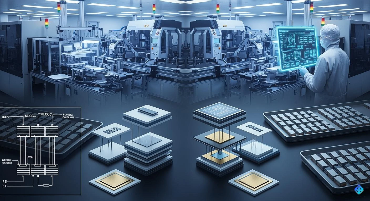
You might ask how multilayer ceramic capacitors are made. First, workers print internal electrodes on thin dielectric sheets. Next, they stack these sheets and press them together. Then, they cut the blocks, fire the chips at high heat, and add external electrodes. The table below lists each main step:
| Step | Description |
|---|---|
| 1 | Printing of internal electrodes onto dielectric sheets |
| 2 | Stacking of dielectric sheets in layers |
| 3 | Pressing the stacked layers to form them |
| 4 | Cutting the blocks to specific dimensions |
| 5 | Firing the cut chips at high temperatures |
| 6 | Coating external electrodes and baking |
| 7 | Plating with nickel and tin for reliability and soldering |
| 8 | Measurements and packing of completed chips |
You must check quality at every stage. This makes sure the capacitor works well in all devices. Today, more people want mlccs:
-
The market for multilayer ceramic capacitors was $13.92 billion in 2024.
-
Experts think it will grow to over $21 billion by 2032.
-
Electric vehicles and 5G networks need these capacitors for better performance.
You can see that making multilayer ceramic capacitors needs careful control at each step. Knowing this process helps you understand why these parts are important.
Key Takeaways
-
MLCCs are made by a careful process. This process has steps like printing, stacking, and firing layers of ceramic and metal.
-
Quality control is very important at each step. It makes sure the capacitors work well in things like smartphones and electric cars.
-
Using pure materials and exact methods helps make strong and dependable capacitors. These capacitors work well and last a long time.
-
Electrical and visual tests check that each capacitor is safe and works right before use.
-
Knowing how MLCCs are made can help you pick better parts for electronics design.
Basic Structure of Multilayer Ceramic Capacitors
Layered Construction
You can learn about multilayer ceramic capacitors by seeing how thin layers are stacked. Manufacturers put many ceramic layers together with metal electrodes between them. This makes a small part that can hold a lot of charge. Each layer works like a tiny parallel-plate capacitor. When you connect all the layers in parallel, the total capacitance gets bigger.
The multilayer design lets mlccs react fast to changes in electricity. You get low resistance and low inductance, so less energy turns into heat. These capacitors are great for high-frequency circuits.
The process begins with preparing raw materials. Workers mix ceramic powders with other things to make thin sheets. These sheets are used to print internal electrodes. Stacking the sheets carefully is important for how well the final product works.
Internal and External Electrodes
Multilayer ceramic capacitors have two kinds of electrodes: internal and external. Internal electrodes are printed using metal pastes, usually made from nickel. Nickel is good because it conducts electricity and is easy to use in factories. TDK was the first to use nickel, which made the process better for everyone.
After stacking, workers add external electrodes. These connect to the inside layers and let you attach the capacitor to a circuit. The materials chosen for both types of electrodes affect how well the part works and how long it lasts.
Here is a table that shows the main materials used and how they change performance:
| Material Type | Description | Performance Impact |
|---|---|---|
| Dielectric Material | Layers of ceramic powders, often barium titanate. | Controls capacitance, stability, and temperature behavior. |
| Metal Electrodes | Nickel, silver, or palladium for printing of internal electrodes. | Affects conductivity, reliability, and manufacturing compatibility. |
You can see that preparing raw materials and using ceramic powders are important for making a good product. The right materials and careful printing of internal electrodes help your capacitor work well in many situations.
Raw Materials and Slurry Preparation
Ceramic Powder Mixing
You begin making mlccs by getting ceramic powders ready. These powders make up most of the multilayer ceramic capacitors. The powders must be very pure. If there is dirt or other chemicals, the capacitor might not work well. It may also not last long. Even a tiny bit of dirt can cause big problems later.
You mix the fine ceramic powder with solvents and resin binders. This makes a thick liquid called slurry. The slurry should be smooth and even. If it has lumps or rough spots, the mlcc layers will not be strong. They also might not work right. Think of the slurry like batter for a cake.
The table below shows how pure the main ceramic compounds must be:
| Compound | Purity Level (%) | Source |
|---|---|---|
| CuO | 99.0 | Alfa Aesar |
| TiO2 | 99.5 | Alfa Aesar |
| Nb2O5 | 99.5 | Alfa Aesar |
| BaCO3 | 99.8 | Alfa Aesar |
| SnO2 | 99.9 | Alfa Aesar |
Note: Using very pure materials helps stop defects. It also keeps the electrical properties steady.
Electrode Material Selection
You also need to pick the right metals for the electrodes inside mlccs. The metal you choose changes how well the capacitor works. It also changes how much it costs. Here are the most common choices:
-
Noble metals like silver and palladium work well. They can handle very high heat and do not break down. They also give great electrical performance.
-
Many companies use cheaper base metals like copper and nickel. These metals cost less but do not work as well as noble metals.
-
Base metal electrodes are used for class 2 capacitors. These do not need to be as exact.
When you use pure materials and mix them well, you help make a strong process. This careful work helps you build mlccs that work well in many electronic devices.
Layer Formation and Electrode Printing
Tape Casting Process
You begin making multilayer ceramic capacitor chips by making thin ceramic sheets. This uses a tape casting process. First, you pour the slurry onto a moving surface. Then, you spread it out with a doctor blade. The blade sets how thick the sheet is. Rollers help keep the sheet smooth. You must pay close attention to every step. The layers need to be the same thickness for the mlccs to work well.
Precision is very important in this process. New machines let you control the thickness from 1 to 30 micrometers. There is only a small amount of error allowed. You also check how rough the surface is and how wide the tape is. Automation helps you change the speed, how thick the slurry is, and how tight the tape is. These controls help you make ceramic layers without defects.
Tip: If the layers are always the same thickness, the mlccs work better in high-frequency circuits.
Here is a table that lists the main things you need to control for tape casting:
| Parameter | Description |
|---|---|
| Thickness Control | Precise control from 1-30μm (within 3-5% tolerance) |
| Surface Roughness | Guide roller surface roughness ≤ Ra 0.8S |
| Casting Width Accuracy | ±1.5 mm |
| Slurry Spreading | Smooth slurry spreading essential for high-density MLCC production |
| Film Positioning Accuracy | Exceptional film positioning accuracy with ultrasonic web guiding system |
| Drying Technology | High-efficiency over-roll and suspended drying tunnel for uniform, rapid tape drying |
| Temperature Control | Six independent drying zones with PID temperature controllers |
| Automation | Advanced automation systems control casting speed, slurry viscosity, and substrate tension |
| Safety Measures | Continuous monitoring of solvent concentration and explosion-proof motors in oven zones |
You have to control the green tape thickness very carefully. How fast you cast and how wide the blade is will change the tape thickness. If you go slower, you get better accuracy. Thin tapes need the right speed to stay even. Nano-ceramic slurries help you control how the slurry flows. This makes strong and even sheets for stacking.
Printing Inner Electrodes
After you make the ceramic sheets, you print the inner electrode patterns. You use a special paste that conducts electricity. You put the paste on the sheets in a set pattern. Most people use screen printing for this. You put a patterned screen on a roll printer. The printer spreads the electrode ink on the tape. After printing, you dry the sheets. This gets them ready for stacking.
-
You can use screen printing or gravure printing for this job.
-
The electrode paste has nickel or other metals in it.
-
The pattern must match the design of the mlcc.
Note: Printing the inner electrodes the right way is very important for good mlccs.
You need to make sure the electrode patterns line up on each layer. This step is important for how well the mlcc works. If the patterns are wrong, the capacitor will not work. You must check the sheets before you move to the next step.
Now you have ceramic sheets with printed electrodes. You are ready to stack the sheets. This step builds the many layers that give mlccs their high capacitance.
Stacking, Lamination, and Cutting
Layer Alignment and Stacking
You start this stage by stacking the ceramic sheets with printed electrodes. Each sheet must line up perfectly with the others. If you do not align the layers, the finished capacitors may not work well. Even a small shift can cause problems like short circuits or cracks.
Automotive multilayer ceramic capacitors need very precise alignment. As you add more layers, the risk of misalignment grows. Factories use special inspection systems with distortion-free imaging and dynamic focus control. These tools help you keep every layer in the right place.
You follow a careful order:
-
Cut the ceramic sheets to the same size.
-
Print the metal electrodes on each sheet.
-
Stack the sheets with electrodes slightly offset.
-
Use machines to align the layers with micron-level accuracy.
This careful stacking helps you build capacitors that last longer and work better.
Lamination (Pressing)
After stacking, you press the layers together. This step removes air pockets and makes the stack solid. You use heat and pressure to bond the sheets. The lamination process gives the capacitor its strength and shape.
-
Pressing the layers ensures tight binding.
-
Heat helps the materials stick together.
-
The process creates a compact block, ready for the next steps.
If you skip this step or do it wrong, the capacitors may break or fail during use.
Cutting Chips
Once you finish lamination, you cut the block into small chips. Each chip becomes a single capacitor. You use machines to slice the block into exact sizes, such as 1.0 mm × 0.5 mm or 1.6 mm × 0.8 mm. The cutting and firing steps are critical for making uniform capacitors.
Here is a simple table showing the main chip sizes:
| Chip Size (mm) | Use Case |
|---|---|
| 1.0 × 0.5 | Smartphones, tablets |
| 1.6 × 0.8 | Automotive, industry |
You must cut each chip cleanly. If you do not, the capacitors may have rough edges or cracks. Clean cutting helps the multilayer ceramic capacitors stay strong during the firing process and in real-world use.
Sintering and Electrode Application
Binder Burnout and Sintering
Now you reach an important step in making multilayer ceramic capacitors. After cutting the laminated block into chips, you must get rid of the organic binders. These binders hold the layers together. This step is called binder burnout. You heat the chips to about 400°C. The heat breaks down the organic stuff. If you do not remove these binders, they can leave behind residue. This leftover material can cause trouble during firing and make the capacitor work worse.
Here is a table that shows the usual temperatures for this step:
| Process | Temperature | Duration |
|---|---|---|
| Binder Burnout | 400°C ± 3°C | N/A |
| Sintering | 1000–1300°C | Several hours |
Next, you start the firing step, which is also called sintering. You heat the chips to very high temperatures, between 1000°C and 1300°C. This step melts the ceramic layers and internal electrodes together. The firing makes the chips strong and gives them their final shape. You must watch the temperature and time closely. If you do not, the layers or internal electrodes might crack or move.
Good binder burnout and firing help you make strong multilayer ceramic capacitors with steady electrical properties.
Applying External Electrodes
After firing, you need to connect the inside of the capacitor to the outside. You do this by putting external electrodes on the chip. You put a special paste on the ends of the chip. This paste has metals that carry electricity. The coating of external electrodes wraps around the sides of the chip. This design lets the electrodes touch the internal electrodes inside the layers. You make the bonding area bigger by using the sides and corners of the chip. This way, the capacitor stays small but strong.
You can see how the coating of external electrodes works:
-
The first electrode parts go on the two main surfaces.
-
The second parts cover the side surfaces.
-
The third parts stretch from the main surfaces onto the sides.
This way, you connect all the internal electrodes to the outside. You keep the capacitor small and dependable.
Plating and Baking
You finish making the capacitor by adding more metal layers to the external electrodes. This step is called plating. You use metals like copper, nickel, tin, silver, palladium, or gold. Each layer protects the electrodes and helps with soldering. You might also treat the surface to make it resist water or attract water. You add a nickel plating layer to stop cracks from forming when the capacitor is used.
Here is a table that shows common metals for plating:
| Plating Layer | Metals Used |
|---|---|
| First Layer | Cu, Ni, Sn, Ag, Pd, Ag-Pd alloys, Au |
| Second Layer | Cu, Ni, Sn, Ag, Pd, Ag-Pd alloys, Au |
You bake the chips after plating. This step makes the coating of external electrodes hard and tough. Now, your multilayer ceramic capacitors are ready for testing and use in electronic devices.
Testing and Quality Control in MLCCs
Electrical Testing
Every capacitor needs careful testing before shipping. Electrical testing checks if the capacitor works right. Special machines measure important features. These tests show if the capacitor meets the rules for performance and reliability.
Here is a table showing the main electrical tests used:
| Test Type | Description |
|---|---|
| Capacitance Value | Measures actual capacitance against specified tolerance bands. |
| ESR (Equivalent Series Resistance) | Assesses internal resistance at a specified frequency to detect degradation. |
| Leakage Current | Tests for current flow through the dielectric under rated voltage to identify potential failures. |
| Capacitance at 1kHz/1MHz | Checks performance at designated frequencies. |
| Dissipation Factor | Evaluates energy loss in the capacitor, indicating efficiency. |
| Insulation Resistance | Measures the resistance of the capacitor's dielectric to ensure reliability. |
| DC Bias Sensitivity Check | Assesses performance under varying DC voltage conditions for Class II dielectrics. |
These tests help find problems early. If a defect is found, you take out the bad capacitor. This keeps your products safe and reliable.
Visual Inspection
You also need to check each capacitor by looking at it. Visual inspection finds defects that machines might miss. Magnifying tools and bright lights help you see the surface and edges. You look for cracks, chips, or other damage.
Common defects found during visual inspection include:
-
Cracks that connect electrodes or start from terminations
-
Uneven construction, like different dielectric thickness
-
Delaminations, where layers come apart inside the capacitor
-
Voids that make the dielectric thinner or affect cover plates
-
Sample preparation defects that look like real flaws
Any capacitor with these defects must be removed. Careful measuring and packing come next. Only the best capacitors go to customers. This process builds trust and keeps your products reliable.
Tip: You get better quality by using both electrical testing and visual inspection. This way, you catch hidden and visible defects.
How Multilayer Ceramic Capacitors Are Made: Summary
Key Steps Recap
You learned how each step changes the final capacitor. Here is a quick summary of how to make a multilayer ceramic capacitor:
-
Mix pure ceramic powders with binders to make a smooth slurry.
-
Cast thin sheets and print inner electrodes on every layer.
-
Stack the sheets carefully and press them together.
-
Cut the block into small chips.
-
Remove binders and fire the chips at high heat.
-
Add external electrodes to connect inside layers to the outside.
-
Plate and bake the external electrodes for strength and soldering.
-
Test each chip for electrical and visual quality.
Each step is important. You must pay close attention, especially when you add external electrodes. These parts help the capacitor work in your devices.
Importance of Precision
Precision makes multilayer ceramic capacitors safe and reliable. You control temperature, atmosphere, and cooling with advanced systems. You inspect each chip after sintering. Automated machines check for defects and test electrical values like capacitance and insulation resistance. You use external electrodes in many steps, so you must apply them carefully. If you do not, the capacitor might fail.
-
Low equivalent series resistance keeps the capacitor cool in high-power circuits.
-
Less heat means fewer failures.
-
You need to know the self-resonant frequency for best performance.
-
You must use external electrodes that connect well to the inner layers.
Murata and other companies use advanced technology to make thin layers and fine electrode patterns. This keeps capacitors stable and reliable. You also follow strict sampling plans and test chips under tough conditions. These steps show why precision matters. When you use high-quality powders and metals, you waste less and keep costs down. You can trust your capacitor to work in any device because you control every detail, especially when you add external electrodes.
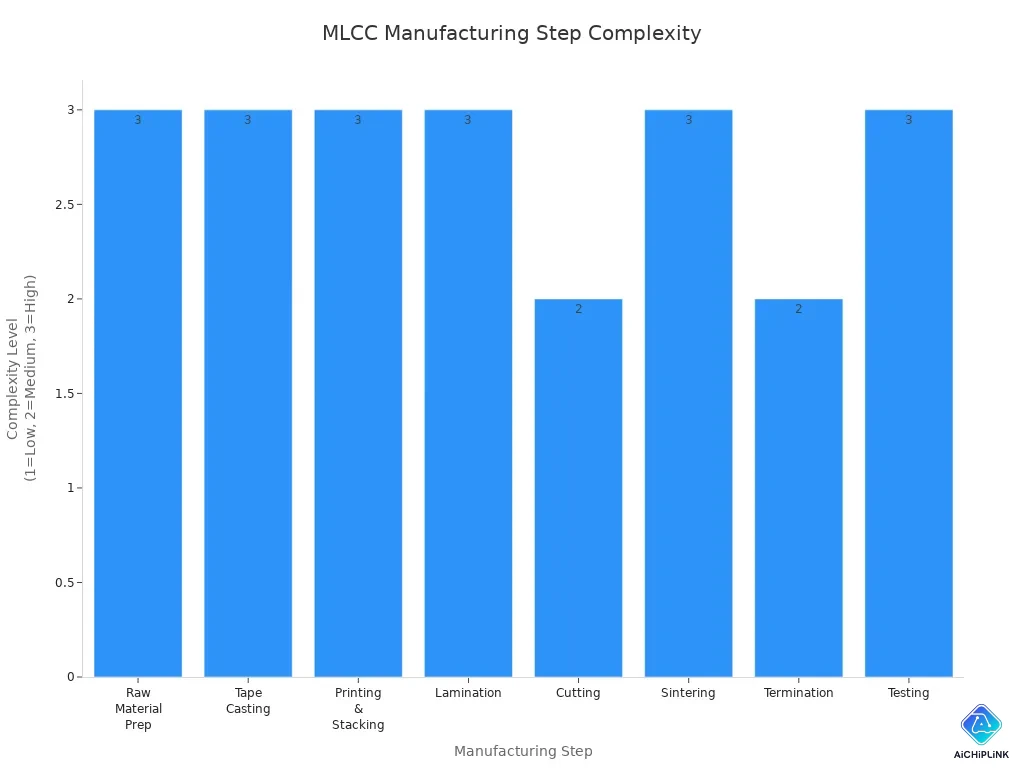
You can see that every step changes how well a capacitor works. Each part of the process needs careful work and skill. From getting raw materials to testing, every stage matters. The table below shows how hard each step is:
| Step | Description | Complexity Level |
|---|---|---|
| Raw Material Prep | Involves finding and getting materials ready for making capacitors. | High |
| Tape Casting | This step makes thin ceramic layers with great care. | High |
| Printing & Stacking | You must stack and print layers very accurately. | High |
| Lamination | Layers are pressed together in special conditions. | High |
| Cutting | You cut the stacks into the right sizes with care. | Medium |
| Sintering | This step uses heat to make the layers solid and strong. | High |
| Termination | Electrodes are added to the capacitors with careful work. | Medium |
| Testing | Each capacitor is tested to make sure it works well. | High |
Knowing these steps helps you pick the best parts for your projects. When you learn how MLCCs are made, you can make smarter choices for your designs.

Written by Jack Elliott from AIChipLink.
AIChipLink, one of the fastest-growing global independent electronic components distributors in the world, offers millions of products from thousands of manufacturers, and many of our in-stock parts is available to ship same day.
We mainly source and distribute integrated circuit (IC) products of brands such as Broadcom, Microchip, Texas Instruments, Infineon, NXP, Analog Devices, Qualcomm, Intel, etc., which are widely used in communication & network, telecom, industrial control, new energy and automotive electronics.
Empowered by AI, Linked to the Future. Get started on AIChipLink and submit your RFQ online today!
Frequently Asked Questions
What is the main purpose of multilayer ceramic capacitors?
Multilayer ceramic capacitors store and release electrical energy. They help keep voltage steady in electronic devices. These parts also filter signals. You can find them in things like smartphones, computers, and cars.
How do you ensure MLCCs are reliable?
Each capacitor goes through electrical tests and visual checks. Machines measure things like capacitance, resistance, and leakage. If a chip has a problem, it gets removed. Careful quality control keeps devices safe.
Why do manufacturers use electrolytic plating in MLCC production?
Electrolytic plating adds metal layers to external electrodes. This helps the capacitor connect better when soldered. It also protects against rust and damage. The process helps the capacitor last longer in tough places.
Can you recycle multilayer ceramic capacitors?
You can recycle MLCCs, but it is not easy. Special places recover the metals and ceramics inside. Recycling helps cut down on waste and saves important materials.
What happens if MLCCs fail in a circuit?
If an MLCC fails, your device might stop working right. You could see signal loss or overheating. Sometimes, a failed MLCC causes a short circuit. You should replace bad capacitors as soon as possible.