Introduction
Capacitance symbols appear throughout electronics in three main contexts: mathematical formulas (C for capacitance), circuit schematics (graphical symbols showing capacitor types), and physical component markings (values like 10µF). Understanding these symbols is essential for reading circuit diagrams, calculating circuit behavior, and selecting the correct components for electronics projects. This comprehensive guide explains all capacitance symbols, from basic notation to advanced schematic conventions.
Basic Capacitance Symbol & Formula
Mathematical Symbol: C
Capacitance is represented by the letter C in formulas and equations.
Fundamental Formula:
Q = C × V

Where:
Q = Charge (Coulombs, C)
C = Capacitance (Farads, F)
V = Voltage (Volts, V)
Why "C"?
- Capacitance
- Capacity (historical term for charge storage ability)
- Universal symbol across all electrical engineering standards
Common Formulas Using C:
1. Capacitive Reactance:
Xc = 1 / (2πfC)

Where:
Xc = Capacitive reactance (Ohms, Ω)
f = Frequency (Hertz, Hz)
C = Capacitance (Farads, F)
π = Pi (3.14159...)
2. Capacitor Energy Storage:
E = ½CV²

Where:
E = Energy (Joules, J)
C = Capacitance (Farads)
V = Voltage (Volts)
3. Time Constant (RC Circuit):
τ = R × C

Where:
τ = Time constant (seconds, s)
R = Resistance (Ohms, Ω)
C = Capacitance (Farads)
Schematic Symbols for Capacitors
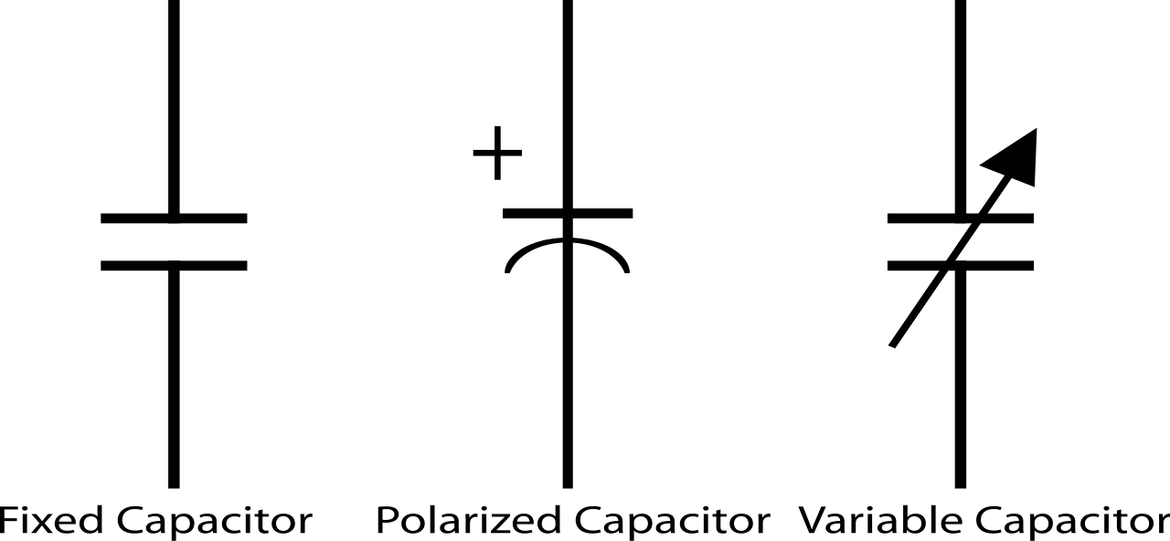
Non-Polarized Capacitor Symbol
Standard Symbol (IEEE/ANSI):
  ──||──

Two parallel lines (representing plates)
Connected to leads on each side
European Symbol (IEC):
  ──∥──

Similar to IEEE but with slightly different line style
When to Use:
- Ceramic capacitors
- Film capacitors (polyester, polypropylene)
- Mica capacitors
- Any capacitor without polarity
Polarized Capacitor Symbol
Electrolytic Capacitor:
  ──|├──
    +

Curved line indicates negative terminal
Straight line indicates positive terminal
"+" marking shows positive side
Why Different Symbol?
- Indicates polarity requirement
- Warns that incorrect connection damages component
- Prevents reverse voltage application
Types Using This Symbol:
- Aluminum electrolytic capacitors
- Tantalum capacitors
- Some polymer capacitors
Variable Capacitor Symbol
Adjustable Capacitance:
  ──||──
    ↗
   (arrow through symbol)

Arrow indicates mechanical or electrical adjustment
Types:
- Trimmer capacitors: Small adjustment (circuit tuning)
- Tuning capacitors: Large adjustment (radio tuning)
- Varactor diodes: Voltage-controlled capacitance
Specialty Symbols
Feed-Through Capacitor:
  ──╫══╫──
  (capacitor with ground connection in middle)
Motor Run Capacitor:
  ──||──
    AC

Special marking "AC" indicates AC-rated
Unit Symbols & Notation
Capacitance Units
Primary Unit: Farad (F)
The Farad is very large—most practical capacitors use sub-multiples:
| Unit | Symbol | Value | Common Use |
|---|---|---|---|
| Farad | F | 1 F | Supercapacitors only |
| millifarad | mF | 10⁻³ F = 0.001 F | Rare (avoid confusion with µF) |
| microfarad | µF or uF | 10⁻⁶ F | Most common (electrolytics) |
| nanofarad | nF | 10⁻⁹ F | Film capacitors |
| picofarad | pF | 10⁻¹² F | Ceramic, RF circuits |
Symbol Variations:
µF (Microfarad):
- Preferred: µF (Greek letter mu)
- Alternative: uF (when µ unavailable, e.g., keyboards)
- Avoid: mF (often confused with millifarad)
Examples:
- 10µF = 10 microfarads = 0.00001 F
- 100nF = 0.1µF = 100 nanofarads
- 1000pF = 1nF = 0.001µF
Unit Conversion Table
1 F     = 1,000,000 µF
1 µF    = 1,000 nF
1 nF    = 1,000 pF

Example conversions:
47µF    = 47,000 nF = 47,000,000 pF
0.1µF   = 100 nF = 100,000 pF
470pF   = 0.47 nF = 0.00047 µF
Reading Capacitor Markings
Direct Marking (Common on Large Capacitors)
Electrolytic Capacitors:
Marking: "220µF 25V"

220 = Capacitance value
µF = Unit (microfarads)
25V = Maximum voltage rating
Film Capacitors:
Marking: "0.1µF 630V"

0.1µF = Capacitance
630V = Voltage rating
Three-Digit Code (Ceramic Capacitors)
Format: XYZ
Decoding:
- XY = First two digits of capacitance
- Z = Number of zeros to add
- Unit = Always picofarads (pF)
Examples:
Code: 104
1st digit: 1
2nd digit: 0
Zeros to add: 4 (10 followed by 4 zeros)
Result: 100,000 pF = 100 nF = 0.1µF
Code: 223
Digits: 22
Zeros: 3 (22 followed by 3 zeros)
Result: 22,000 pF = 22 nF = 0.022µF
Code: 475
Digits: 47
Zeros: 5
Result: 4,700,000 pF = 4700 nF = 4.7µF
Special Codes:
- Code ends in "8": Multiply by 0.01 (e.g., 228 = 22 × 0.01 = 0.22 pF)
- Code ends in "9": Multiply by 0.1 (e.g., 229 = 22 × 0.1 = 2.2 pF)
Letter Code (Tolerance)
Added after numeric code:
| Letter | Tolerance | Meaning |
|---|---|---|
| J | ±5% | Standard ceramic |
| K | ±10% | Common ceramic |
| M | ±20% | General purpose |
| Z | +80%, -20% | Asymmetric (class 2 ceramic) |
Example:
Marking: "104K"
Capacitance: 100,000 pF = 0.1µF
Tolerance: ±10%
Actual range: 0.09µF to 0.11µF
Voltage Rating Codes
Letter codes for voltage (some ceramic caps):
| Code | Voltage |
|---|---|
| 0J | 6.3V |
| 1A | 10V |
| 1C | 16V |
| 1E | 25V |
| 1H | 50V |
| 2A | 100V |
Capacitance in Circuit Analysis
Symbol Usage in Calculations
Series Capacitors:
Circuit symbol:
C₁ ── C₂ ── C₃

Formula using C symbols:
1/C_total = 1/C₁ + 1/C₂ + 1/C₃
Parallel Capacitors:
Circuit symbol:
    ├─ C₁ ─┤
────┤       ├────
    ├─ C₂ ─┤

Formula:
C_total = C₁ + C₂
Subscript Notation
Common Subscripts:
- C₁, C₂, C₃... = Individual capacitors in circuit
- C_total or C_eq = Total/equivalent capacitance
- C_in = Input capacitance
- C_out = Output capacitance
- C_stray = Parasitic capacitance
Advanced Symbol Notation
Polarization Indicators
Polarity Markings on Schematics:
Positive terminal marked:
──|├── +

Or with voltage annotation:
──|├── Vcc (connected to positive supply)
PCB Silkscreen:
- White band = Negative terminal (electrolytic)
- "+" symbol = Positive terminal
- Arrow pointing to negative (some SMD)
Parasitic Capacitance Symbols
Dotted Lines (Indicating Unwanted Capacitance):
       ┆┆┆
   ────┆┆┆──── (parasitic capacitance between traces)
       ┆┆┆
Usage:
- Model PCB trace capacitance
- Transistor junction capacitance
- Cable capacitance
Quick Reference Guide
Symbol Summary Table
| Capacitor Type | Schematic Symbol | Polarity? | Common Values |
|---|---|---|---|
| Ceramic | ──∥── | No | 1pF - 10µF |
| Film | ──∥── | No | 100pF - 10µF |
| Electrolytic | ──|├── | Yes (+/-) | 1µF - 10,000µF |
| Tantalum | ──|├── | Yes (+/-) | 0.1µF - 1000µF |
| Variable | ──∥──↗ | No | 5pF - 500pF |
Unit Conversion Quick Reference
To convert:
pF → nF: Divide by 1,000
nF → µF: Divide by 1,000
µF → F: Divide by 1,000,000

To convert back:
µF → nF: Multiply by 1,000
nF → pF: Multiply by 1,000
Common Mistakes to Avoid
Mistake 1: Confusing µF with mF
❌ Wrong: Writing "mF" for microfarad
✅ Correct: µF (microfarad) or uF (if µ unavailable)
Why it matters: mF = millifarad = 1000µF (huge difference!)
Mistake 2: Reversed Polarity Symbol
❌ Wrong: Installing electrolytic backwards
✅ Correct: Check "+" marking, curved line = negative
Consequence: Capacitor failure, possible explosion
Mistake 3: Misreading Three-Digit Code
❌ Wrong: Reading "104" as "104 pF"
✅ Correct: 104 = 100,000 pF = 0.1µF
Mistake 4: Unit Confusion in Calculations
❌ Wrong: Mixing units (C₁ = 10µF + C₂ = 1000pF = 1010?)
✅ Correct: Convert first (10µF + 0.001µF = 10.001µF)
Conclusion
Understanding capacitance symbols—from mathematical notation (C in formulas) to schematic representations (polarized vs non-polarized) and unit abbreviations (µF, nF, pF)—is essential for reading circuit diagrams, calculating circuit behavior, and selecting correct components. Mastering these symbols prevents common mistakes like reversed polarity, unit confusion, and incorrect component selection, enabling confident electronics design and troubleshooting.
Key Takeaways:
✅ Mathematical symbol: C represents capacitance in all formulas
✅ Non-polarized schematic: ──||── (ceramic, film capacitors)
✅ Polarized schematic: ──|├── (electrolytic, tantalum—mind polarity!)
✅ Common units: µF (microfarad), nF (nanofarad), pF (picofarad)
✅ Three-digit code: XYZ = XY followed by Z zeros (always pF)
✅ Unit conversion: 1µF = 1,000nF = 1,000,000pF
✅ Avoid: Confusing µF with mF, reversing polarized capacitors
Building electronics projects? Visit AiChipLink.com for capacitor selection guidance, schematic reading help, and circuit design consultation.

Written by Jack Elliott from AIChipLink.
AIChipLink, one of the fastest-growing global independent electronic components distributors in the world, offers millions of products from thousands of manufacturers, and many of our in-stock parts is available to ship same day.
We mainly source and distribute integrated circuit (IC) products of brands such as Broadcom, Microchip, Texas Instruments, Infineon, NXP, Analog Devices, Qualcomm, Intel, etc., which are widely used in communication & network, telecom, industrial control, new energy and automotive electronics.
Empowered by AI, Linked to the Future. Get started on AIChipLink.com and submit your RFQ online today!
Frequently Asked Questions
What does the C symbol mean in electronics?
The symbol “C” in electronics represents capacitance, which is the ability of a component to store electrical charge and is measured in Farads (F). It is commonly used in circuit formulas and as a label in schematics (e.g., C1, C2) to identify capacitors, making it a standard notation in electrical engineering.
How do you read capacitor schematic symbols?
Capacitor schematic symbols indicate the type and polarity of the component. Non-polarized capacitors are shown as two parallel lines and can be connected in any direction, while polarized capacitors include a curved line or polarity marking to show the required positive and negative terminals. Additional labels specify capacitance value, voltage rating, and component number.
What does µF mean on a capacitor?
µF (microfarad) is a unit of capacitance equal to one-millionth of a Farad. It is commonly used to describe capacitor values, especially for electrolytic capacitors, and may also appear as “uF” when the µ symbol is not available.
How do you decode the three-digit code on ceramic capacitors?
The three-digit capacitor code represents capacitance in picofarads, where the first two digits are the value and the third digit is the multiplier (number of zeros). This system allows compact labeling of small capacitors, often combined with a letter indicating tolerance.
What's the difference between polarized and non-polarized capacitor symbols?
The key difference is that polarized capacitors require correct orientation, while non-polarized capacitors do not. Polarized symbols indicate positive and negative terminals and must be installed correctly, whereas non-polarized capacitors can be connected in either direction and are commonly used in AC circuits.